Star Phantom ULB42 Quick guide

PLITSTR299 REV. D 3/28/05
INSTALLATION AND INSTRUCTION MANUAL
FOR
The
Undercover Interior LED Lightbar
Model ULB42

1
The Phantom®uses state-of-the-art Light Emitting Diode (LED)
technology. This warning light is comprised of ultra-high intensity LEDs that
are operated by a micro-controller to efficiently produce light output with
lifetimes up to 100,000 hours.
IMPORTANT: Please read all of the following instructions before installing your new
Star Phantom®LED undercover lightbar.
CAUTION: Please be sure to check that your cigarette plug outlet is properly fused. Testing the
light before this fuse is properly installed will void the warranty on the light.
WARNING!!!! Care should be taken when positioning this warning light so that the light and/or
cord does not interfere with the proper operation of the driver-side or passenger-
side airbag! Failure to heed this warning may result in serious or fatal injury.
Please Note:
These instructions are provided as a general guideline only. Specific
mounting and/or wiring, may be necessary and are the sole responsibility of the
installer. Star Headlight & Lantern Co., Inc. assumes no responsibility for th
e
integrity of the installation for this or any of its products.
CAUTION:
All of our DC powered warning lights are
polarity sensitive. These lights are polarity protected only if
the appropriate fuse is used. All wires connected to the
positive terminal of the battery should be fused at the
battery for their rated load. Testing the light before this
fuse is properly installed will void the warranty on the
light.
NOTICE
Due to continuous product improvements, we must reserve the right to change any specifications and
information, contained in this manual at any time without notice. Star Headlight & Lantern Co., Inc.
makes no warranty of any kind with regard to this manual, including, but not limited to, the implied
warranties of merchantability and fitness for a particular purpose. Star Headlight & Lantern Co., Inc.
shall not be liable for errors contained herein or for incidental or consequential damages in connection
with the furnishing, performance, or use of this manual.

2
Mounting Instructions
The mounting hardware enclosed with your Star Phantom®should
include the following:
2Single-Slotted "L" Brackets
2Forked "L" Brackets
2 Double-Slotted "L" Brackets
2Slotted Straight Brackets
4#8-32 3/8” Phillip's Head Screws
10 #8 x 3/8 Self-Tapping Phillip’s Head Screws
14 #8 Flat Washers
4#8 Tooth Washers
4#8 Nut
1Rubber Channel Gasket
The ULB42 is designed to be mounted in the front windshield of a vehicle
using both the pre-existing visor clips as well as the corner posts.
VISOR CLIP BRACKET INSTALLATION
The Star Phantom
is designed to be mounted on the inside of
your vehicle. It is not intended for exterior applications and is not
warranted against water damage.
It is the sole responsibility of the owner to ensure the warning light is
secure. Check your light every time you enter the vehicle to ensure that it
is mounted securely. The manufacturer assumes no responsibility for the
secure mounting of this light.
The following mounting instructions describe the standard, most common
way to mount this light. This method may or may not apply to your vehicle.
Because vehicles can vary widely in their design, it may be necessary to
configure the brackets differently than described. Some applications may
require you to design your own custom brackets. The installer assumes all
responsibility for the integrity of the installation.
It is the sole responsibility
of the owner to ensure the traffic director is secure.

3
1. Connect one of the slotted
"L" brackets to one of the
forked "L" brackets using
one of the screws, a flat
washer, a tooth washer, and
a nut.
2. Repeat this using the other slotted
"L" bracket and forked bracket.
You should now have two
adjustable forked mounting
brackets.
3. Locate the two visor clips
on the vehicle. The style
may vary from vehicle to
vehicle. Some styles
use only one screw each,
while others may have
more. Verify that both
visor clips are a
minimum of 3” from the
center of the window,
and a maximum of 8”
from the center.
4. Loosen (or remove if
necessary) both visor
clips enough that one of
the forked brackets can
easily slide under each
of them.
5. Slide one forked
bracket under each
visor clip and tighten
the clip such that it
securely holds each
bracket in place.

4
6. Some vehicles may not have visor
clips appropriate for this application,
or may completely lack any visor
clips. An alternate mounting screw
hole is provided in the bracket for
these situations. This hole can be
used with an appropriate user
supplied screw or other suitable
fastener.
7. If you are using the alternate
mounting screw hole, you will need
to locate the roof brace under the
headliner of the vehicle or some
other appropriate mounting surface.
8. Once you have located a suitable mounting surface, pick an area to
mount the brackets (one on each side) that is a minimum of 3” from the
center of your window and a maximum of 8”.
9. Once you have decided upon the exact locations, determine an
appropriate size screw to penetrate the headliner and securely mount
the brackets to the roof brace. Take care to ensure when selecting a
screw that it is capable of supporting the weight of the light and that it
will not penetrate the roof of the vehicle.
8. Carefully drill any necessary pilot holes in your roof brace. CAUTION:
Take care to ensure when selecting a screw and drilling the hole
that it is capable of supporting the weight of the light and that it
does not penetrate the roof of the vehicle.
9. Install the screws through each bracket as shown below.

5
10. Once the brackets are installed securely, check to see that the bottoms
of the brackets are level. If they are not level, remove the brackets and
carefully bend them as necessary. Reinstall them and check again for
levelness. Repeat this process until the brackets are level.
11. Once the forked brackets are secured in place and leveled, set The
Star Phantom®on top of the brackets with the cig plug exiting from
the passenger side of the unit. The ON/OFF switch will be located on
the driver's side.
12. Using a Philip head screwdriver, loosen the Height Adjustment Screw
slightly and set the lightbar at the desired height. Once your desired
height is set, tighten the screw to secure the bracket.

6
13. After you have set the brackets to the proper height, refer to the
diagram below for the "Safe" areas to attach your forked mounting
bracket. Mark two holes for each bracket.
Star highly recommends marking the desired screw holes first.
Remove the lightbar and measure the marked points to ensure
they are within the "Safe Area".
14. Once you have determined that the marked holes are in the "Safe Drill
Area" use a 1/8" drill to make a pilot hole for your self-tapping screws.
15. After the holes are drilled, replace your Star Phantom®on the
mounting brackets. Use the self-tapping screws to attach the lightbar to
the brackets
CAUTION: Take extreme caution not to over tighten the screws!!!
Over tightening of the screws can strip the holes and result in a
faulty mount.
CORNER POST BRACKET INSTALLATION
1. After the visor clips are installed, you need to attach the corner post
mounting brackets.
Because of the wide variety of mounting
applications, Star Headlight & Lantern Co., Inc.
assumes no responsibility for the secure mounting
of this light. It is the responsibility of the installer
and/or owner to ensure the lightbar is mounted
securely. Check your light every time you enter the
vehicle
to ensure that it is mounted securely.
2"
13"
18"
13"
18"
2"
NO DRILL AREA
NO DRILL AREA
SAFE
DRILL
AREA NO DRILL AREA
SAFE
DRILL
AREA
SAFE DRILLING AREAS FOR ATTACHING
FORKED MOUNTING BRACKETS TO BOTTOM

7
2. Connect one of the double-slotted
"L" brackets to one of the slotted
straight brackets using one of the
screws, a flat washer, a tooth
washer, and a nut.
3. Repeat this using the other
double-slotted "L" bracket
and slotted straight
bracket. You should now
have two adjustable "L"
mounting brackets.
4. Connect one bracket to each end of
your Star Phantom®using the
screws provided. Loosen both
screws slightly to allow for
adjustability when installing the
lightbar.
5. Adjust the mounting
brackets so that they
rest flat against the
corner post on each
side of the vehicle.
6. Once the brackets are adjusted to the desired position, tighten all the
screws on the brackets.
7. Mark the two spots where you will be attaching your screws to the
corner post.

8
8. Loosen the brackets, temporarily slide them aside, and drill a 1/8" hole
in each of the marked locations.
Caution: Be sure to check that there are no wires or anything else
behind the molding that may be damaged by the screw holes.
9. Return the brackets to their original position against the corner post
and use two of the self-tapping screws in each side to secure each
bracket to the corner posts.
10. Once the brackets are securely tightened, check your mount to ensure
the desired angle is achieved. Stand in front of the vehicle and
inspect the light through the front windshield. The screws may be
loosened slightly to allow for any final adjustments necessary.
11. Once all the necessary adjustments are made retighten all the screws.
CAUTION: Take extreme caution not to over tighten the screws!!!
Over tightening of the screws can strip the holes and result in a
faulty mount.
BAFFLE ADJUSTMENT
1. Once the brackets are securely tightened, and the desired angle is achieved you
should adjust the baffle. The baffle will help eliminate any reflection you might
get off the front windshield.
2. Slide the enclosed rubber channel over the front edge of the baffle.
3. Loosen the five Baffle Adjusting Screws located on the bottom of The Star
Phantom®.
4. Slide the baffle forward until it satisfactorily blocks any reflected light.
5. Tighten the Baffle Adjusting Screws to secure the baffle in place.
CAUTION: Take extreme caution not to over tighten the screws!!! Over
tightening of the screws can strip the holes.
CAUTION!!! Once the light is secured, route your cord such that it
does not interfere with the vision of the driver or the operation of
the steering wheel, gear shifter, and/or any airbags.

9
Operating Instructions
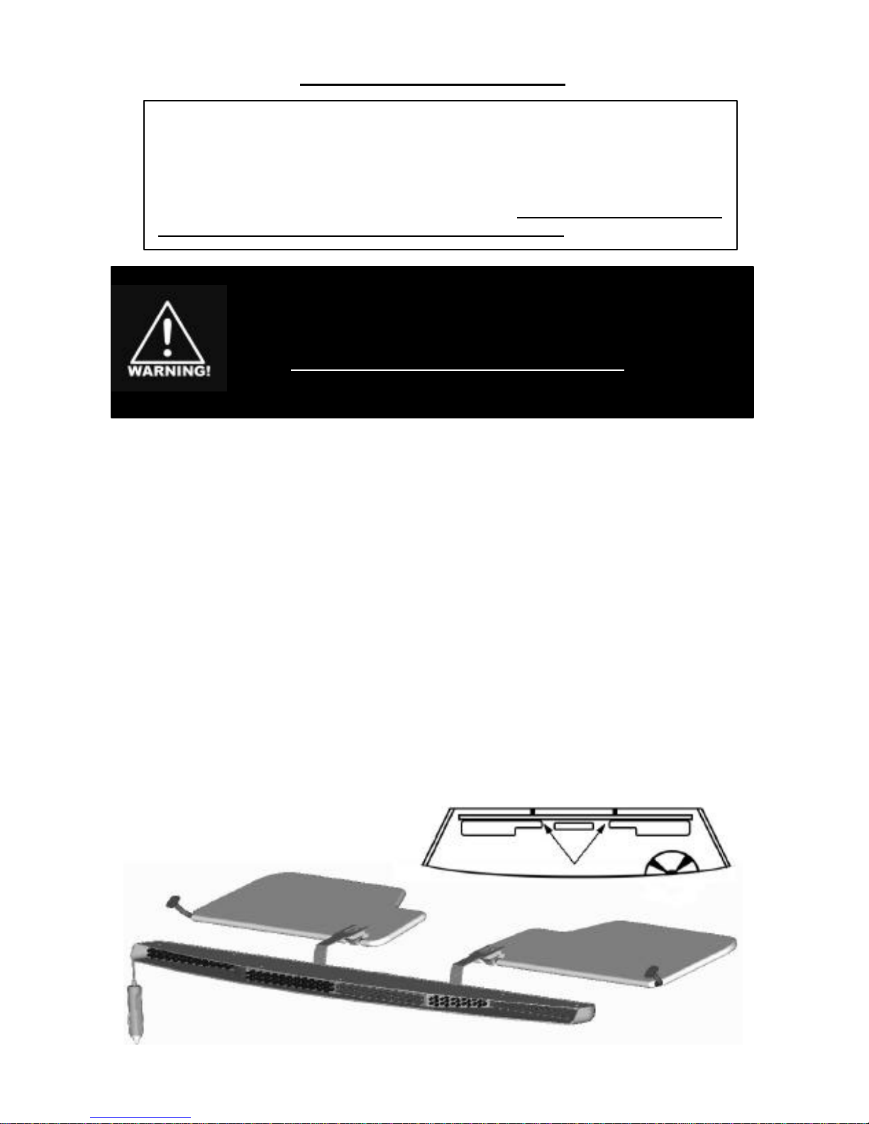
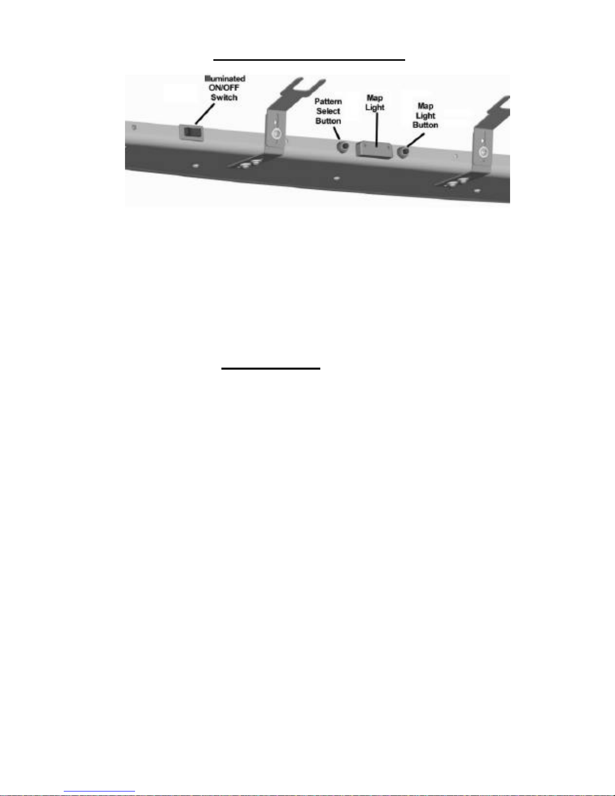
1. The Star Phantom®is designed for simple operation. This unit has
an On/Off switch, a Pattern Select Button, and a Map Light Button.
2. The On/Off switch is located closest to the driver's side. It switches The
Star Phantom®on or off.
3. The button to the left of the map light is the Pattern Select button. This
is a momentary switch. Each time this switch-button is depressed, The
Star Phantom®will cycle to the next pattern. The Star
Phantom®is designed with thirty-five different patterns:
Pattern List
There is also an additional “No Output” pattern included after the DEMO MODE
(shown at #36 above). After the “No Output” pattern, the patterns will start to
cycle through again. You might find it helpful to use this "No Output" pattern to
find your place in the pattern list when cycling through. The PhantomTM will
“remember” the last selected pattern when switched off and that pattern will be
displayed the next time the light is switched on.
1. Slow Alternating Single
2. Fast Alternating Single (Default)
3. Slow Simultaneous Single
4. Fast Simultaneous Single
5. Quad Flash Burst w/ POP
6. Five Flash Burst w/ POP
7. Triple Alternating Fade
8.. Triple Alternating Fast Fade
9. Double Alternating Fade
10. Super Slow Alternating
11. Super Slow Simultaneous
12. Triple Flash Simultaneous
13. Five Flash Simultaneous
14. Rapid Alternating Single
15. Triple Flash Alternating
16. Five Flash Alternating
17. Super Fast Single Simultaneous
18. Simultaneous Quad Flash Burst w/ Hold
19. Fast Simultaneous Quad Flash Burst w/ Hold
20. Alternating w/ Short Overlap
21. Triple Alternating w/ Opposite Side Steady
22. Pulse
23. Random-Flicker Flash Combo
24. Random-Flicker w/ Triple Flash Alternating
25. Random-Single Alternating w/ Double
Simultaneous
26. Random-Double Simultaneous w/ Single
Alternating and Triple Alternating w/ Hold
27. Random-Double Simultaneous w/ Triple
Alternating and Double Alternating w/ Hold
28. Random-Double Simultaneous w/ Flicker and
Double Flash Alternating
29. Random-Fast/Slow Alternating Single
30. Random-Five Flash Alternating w/ Off Time
31. ½ Steady, ½ Singleflash †
32. ½ Steady, ½ Singleflash (opposite of #31) †
33. Slow Alternating †
34. Slow Simultaneous †
35. DEMO MODE (cycles through all patterns)
36. No Output † = California Title 13 Patterns

10
4. The right button is the Map Light switch. Located at the center of the
lightbar is the "night vision" map light. Depressing the button once will
illuminate the "night vision" map light. Pressing the button again will
turn the light off.
Once your Star Phantom®is installed, please test all the patterns and
options to familiarize yourself with the various patterns and the operation of
the buttons.
If you have any questions concerning this or any other product, please
contact our Customer Service Department at (585) 226-9787.
If a product must be returned for any reason, please contact our
Customer Service Department to obtain a Returned Goods Authorization
Number (RGA #) before you ship the product back.
Please write the RGA # clearly on the package near the mailing label.

11
ONE YEAR LIMITED WARRANTY
The manufacturer warrants each new product, under normal use, against factory defects in material and
workmanship for one year after the date of purchase. The owner will be responsible for returning to the
Service Center any defective item(s) with the transportation costs prepaid. The manufacturer will, without
charge, repair or replace at its option, products, or part(s), which its inspection determines to be defective.
Repaired or replacement item(s) will be returned to the purchaser with transportation costs prepaid from the
service point. A copy of the purchaser's receipt must be returned with the defective item(s) in order to qualify
for the warranty coverage.
Exclusions from this warranty include, but are not limited to, bulbs, strobe tubes, domes, and/or the finish.
This warranty shall not apply to any light, which has been altered, such that in the manufacturer's judgment,
the performance or reliability has been affected, or if any damage has resulted from abnormal use or service.
This warranty does not apply to defect or damage occurring as a result of disaster, accident, abuse, misuse,
lightning, power surges, or failure to follow instructions in any enclosed manuals. Any damage or defects
occurring as a result of any unauthorized service or repairs by unauthorized persons shall be excluded from
this warranty.
There are no warranties expressed or implied (including any warranty of merchantability or fitness), which
extend this warranty period. The loss of use of the product, loss of time, inconvenience, commercial
loss or consequential damages, including costs of any labor, are not covered. The manufacturer
reserves the right to change the design of the product without assuming any obligation to modify any product
previously manufactured.
This warranty gives you specific legal rights. You might also have additional rights that may vary from state
to state. Some states do not allow limitations on how long an implied warranty lasts. Some states do not
allow the exclusion or limitation of incidental or consequential damages. Therefore, the above limitation(s)
or exclusion(s) may not apply to you.
The Star Phantom
®
uses state-of-the-art Light Emitting Diode (LED)
technology. This undercover lightbar is comprised of ten segments of ultra-
bright LEDs that are operated in a multiplexed mode to efficiently produce light
output with lifetimes up to 100,000 hours. Under normal circumstances, you will
not need to replace any lights in this lightbar. If any of the LED's in your lightbar
do fail, please contact Star Headlight for arrangements to have them repaired.
NOTE: Most failures can be traced to wiring and battery problems. Check "quick-connects and wiring
to insure that correct voltage/polarity is reaching the electronic strobe light/LED beacon.
Table of contents
Other Star Phantom Lighting Equipment manuals