Energetiq LDTLS TLS-EQ77H User manual

Model TLS-EQ77H
LDTLS™
Laser-Driven Tunable Light Source
Operation Manual
Revision 1 November 2016
Part Number DOC-7682

Copyright © 2016 Energetiq Technology Inc. All rights reserved.
Energetiq products are covered by the following patents: US 7435982, 7786455, 8525138,
8969841, 9048000, 9185786; Japan 5410958, 5628253; Korea 10-1507617; UK GB2450045.
All technical information, including drawings, schematics and specifications contained in this
manual are the property of Energetiq and shall not be reproduced in whole or in part without
the written consent of Energetiq. The content of this manual is subject to change without
notice.
Energetiq Technology Inc.
7 Constitution Way, Woburn, MA 01801 USA
Tel. +1 (781) 939-0763
Fax +1 (781) 939-0769
E-mail: [email protected]
http://www.energetiq.com
Fax +1 (781) 939-0769
E-mail: [email protected]
http://www.energetiq.com

TABLE OF CONTENTS
Chapter 1...................................................................................................................................................... 1
General Information....................................................................................................1
Safety............................................................................................................................................... 1
Chapter 2...................................................................................................................................................... 5
Description ....................................................................................................................5
General ........................................................................................................................................... 5
Specifications................................................................................................................................. 6
System Description ...................................................................................................................... 8
Power Supply Controller............................................................................................................. 9
Lamp House................................................................................................................................ 12
Chapter 3.................................................................................................................................................... 13
Installation................................................................................................................... 13
Unpacking.................................................................................................................................... 13
Installation Procedure................................................................................................................ 13
Chapter 4.................................................................................................................................................... 19
Operation.................................................................................................................... 19
Starting.......................................................................................................................................... 19
Stopping ....................................................................................................................................... 19
Monochromator Interface........................................................................................................ 20
Serial Interface ............................................................................................................................ 20
Chapter 5.................................................................................................................................................... 23
Maintenance and Troubleshooting ........................................................................ 23
Optical Alignment...................................................................................................................... 23
Fault Indicator Block Diagram................................................................................................ 31
Appendix A................................................................................................................................................ 33
Engineering Drawings .............................................................................................. 33
Appendix B................................................................................................................................................ 35
Revision History ........................................................................................................ 35
Appendix C................................................................................................................................................ 37
Packaging Instructions.............................................................................................. 37


TLS-EQ77H Operation Manual Rev. 1 1
Chapter 1
GENERAL INFORMATION
Safety
WARNING
General Precautions
There are no user-serviceable parts inside the TLS-EQ77H. For any problems encountered
during operation, please contact Energetiq Technology for assistance. If there is a
component failure, do not attempt to open the Power Supply Controller or Lamp
House enclosure of the TLS-EQ77H.
The TLS-EQ77H utilizes a quartz lamp containing a high-pressure gas fill. Explosion
of the lamp and possible injury from flying fragments can occur if the lamp is
mishandled.
Do not open the enclosure of either the Lamp House or the Power Supply Controller.
Dangerous invisible infrared laser beams and hazardous voltages exist inside the
Lamp House. Opening the chassis both voids the warranty and exposes the user to
dangerous radiation and hazardous voltages.
CAUTION
Use of controls or adjustments or performance of procedures
other than those specified herein may result in hazardous
radiation exposure.
The EQ-77 utilizes an internal Class 4 IR laser
capable of causing severe injury to eyes or skin.
Do not open or attempt to service this unit.
Contact Energetiq regarding any problems with
the unit.

2 TLS-EQ77H Operation Manual Rev. 1
Laser Information
The EQ-77 uses a patented* laser drive system to excite a plasma that radiates in the UV as
well as the visible bands. A class 4 laser is located in the Lamp House enclosure. The optical
configuration of the Lamp House ensures that the direct laser beam cannot exit the unit. The
EQ-77 laser product is designated as Class 1 during all normal operation.
The parameters of the non-accessible internal laser are given below in Table 1.
Wavelength 974 nm
Emission Type CW
Laser Power for classification <36 mW via 7mm measurement
aperture
Beam Diameter ~25 mm at aperture
Divergence >100 mRad
Transverse Beam Mode Diffuse
Table 1: Embedded Laser Parameters
No regular maintenance is required for the TLS-EQ77H. Any service to the system must be
performed only by factory authorized and trained technicians. To avoid injury, under no
circumstances should the user open or modify the Lamp House or Power Supply Controller
enclosure.
The unit must not be operated if the covers are removed or it is defective in any way. Contact
Energetiq if any problems with the equipment are suspected.
*US 7435982, 7786455, 8525138, 8969841, 9048000, 9185786 ; Japan 5410958, 5628253; Korea 10-1507617; UK
GB2450045

TLS-EQ77H Operation Manual Rev. 1 3
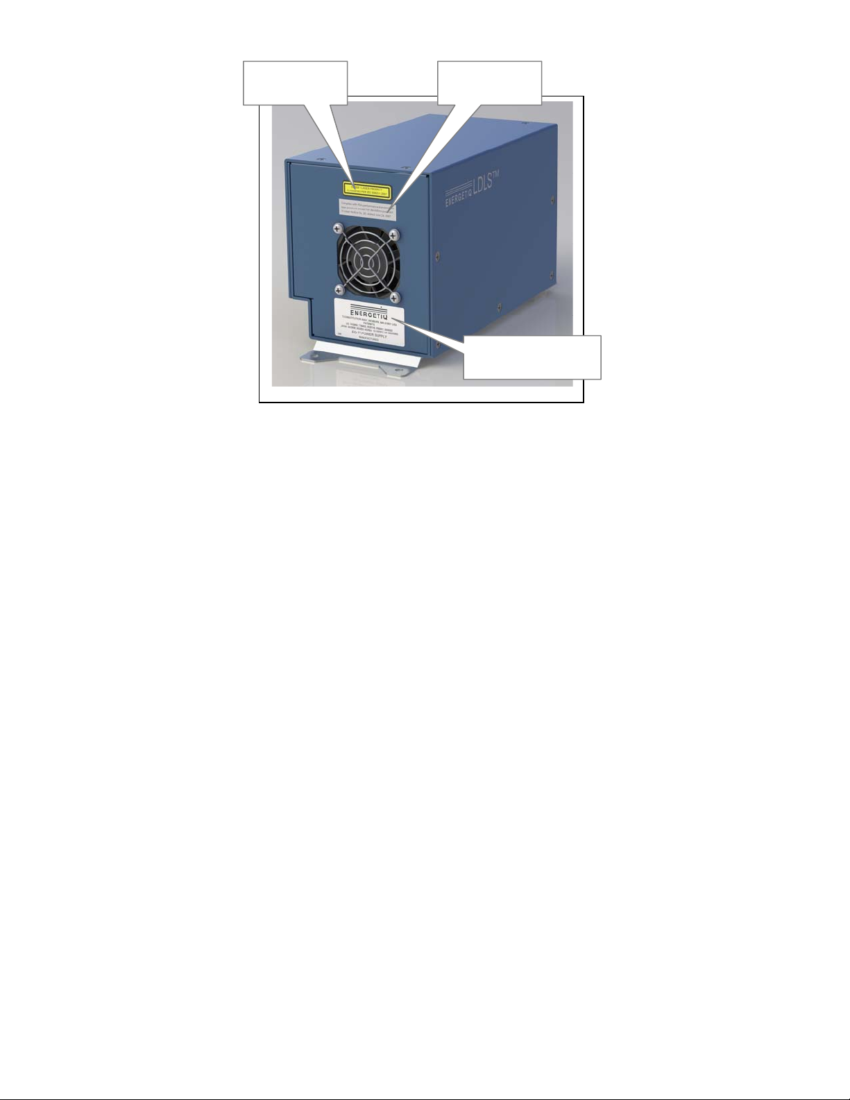
Labels and Safety Notification
The following safety labels appear on the product. Figure 1 shows the location of each label
on the EQ-77 system.
Manufacturer’s identification label – gives the manufacturer’s
name and address, and the model, serial number, and date of
manufacture of the equipment.
Explanatory label – states the classification of the laser product.
Class 1 is the lowest hazard level classification.
Certification label – states that the equipment has been tested
and verified to meet the standards indicated.
4 TLS-EQ77H Operation Manual Rev. 1
Figure 1: Safety Label Locations
Safety Interlocks
The TLS-EQ77H is equipped with interlocks to prevent operation of the device when any of
the following conditions are present:
1. An external interlock is open
2. No bulb is installed
External Interlock
External interlock pins are provided for the customer’s use (see Chapter 3 for connection
details). Any suitable normally-open contact or solid-state switch can operate the interlock
circuit. The contact or switch should be rated for 80mA minimum at 5VDC.
The interlock circuit must be connected to enable the operation of the unit. Should the
interlock connection open during operation, the source is immediately disabled, and all light
output from the aperture ceases.
Certification
Label
Explanatory
Label
Manufacturer’s
Identification label

TLS-EQ77H Operation Manual Rev. 1 5
Chapter 2
DESCRIPTION
General
The TLS-EQ77H is a compact, highly stable tunable light source. It utilizes the Energetiq
EQ-77 Laser Driven Light Source™ as a broadband light source. A monochromator is used
to select the desired output wavelength. The monochromator output is fiber coupled to the
TLS-EQ77H output.
The TLS-EQ77H system consists of a Power Supply Controller unit, Lamp House unit,
Remote Control Unit, Monochromator Power Supply, and interconnecting cables.
Connections to AC power, nitrogen purge gas, and cooling water are required for operation.

6 TLS-EQ77H Operation Manual Rev. 1
Specifications
Optical Performance
Wavelength range: 400 – 1100 nm
Wavelength step size: 2 nm
Sweep time, 2 nm step: 20 ms
Return time, 1100 – 400 nm: 4 s
Output connector: SMA
Fiber output NA: 0.19 ± 0.02
Spectral width FWHM: 6.5 ± 1.5 nm
Wavelength accuracy: ± 1.0 nm
Step repeatability: ± 0.1 nm
Total output power
Wavelength, nm Min. power, mW
400 1.40
700 1.40
950 0.70
1100 0.08
Physical Specifications
Dimensions (H x W x D)
Lamp House: 266 x 432 x 222 mm (10.5 x 17.0 x 8.8 in)
See drawing OTD-7785 for detailed dimensions
Power Supply Controller: 152 x 250 x 132 mm (6.0 x 9.8 x 5.2 in)
See drawing OTD-6881 for detailed dimensions
Weight
Lamp House: 16.6 kg (36.5 lb)
Power Supply Controller: 2.9 kg (6.5 lb)

TLS-EQ77H Operation Manual Rev. 1 7
Utility Requirements
Power Supply Controller Electrical
Voltage: 100 – 240 VAC
Frequency: 50/60 Hz
Power: 350 W max.
Connector: IEC320 C14 inlet
Monochromator Electrical
Voltage: 24VDC
Power: 50W
Connector: 5-pin DIN female
Mating connector: 5-pin DIN male, Switchcraft 05GM5MX or equivalent
Pin connections: pins 3, 5: 24VDC; pins 1, 2, 4: 24V return
Purge gas
Type: Clean dry nitrogen, filtered to 5μm
Supply pressure: 20 psig (0.14 MPa)
Typical flow rate: 0.4 liters/minute
Fittings: 4mm push-to-connect
Cooling water
Flow rate: 1 liter/minute
Temperature: 20 – 24 °C
Cooling capacity: 190 W
Max. inlet pressure: 100 psig (0.69 MPa)
Fittings: 1/4-inch Swagelok
Remote Interface
Digital Inputs
Type: Optocoupler LED
Logic: Active High
Input voltage: 5VDC
Input current: 8mA
External Interlock Input Only (pin 13)
Type: Relay Coil
Logic: Active High
Input voltage: 5VDC
Input current: 80mA
Digital Outputs

8 TLS-EQ77H Operation Manual Rev. 1
Type: Open collector to ground (digital common)
Logic: Active Low
Voltage: 30VDC max.
Sink current: 30mA max.
User Power
Voltage: 5VDC, referenced to digital common
Current: 400mA maximum
Serial Interface
Type: RS-485 4-wire (full duplex)
Connector: Male 9-pin d-sub
Termination: 120 ohms across receiver input (pins 2 and 7)
Interface protocol: see Chapter 4
Port settings: 9600 bps, 8 data bits, 1 stop bit, no parity, no handshaking
Environmental Requirements
Operating
Ambient temperature: 15–35°C
Relative Humidity: non-condensing, 80% max. for temperatures up to 31°C,
decreasing linearly to 50% max. at 35°C.
Pollution Degree 2 (normally only non-conductive pollution; occasional,
temporary condensation possible)
Installation Category II
Indoor use only
Transport
Temperature: -5–70°C
Relative Humidity: non-condensing, 95% max.
System Description
The TLS-EQ77H system consists of a Power Supply Controller unit, Lamp House, Remote
Control unit, Monochromator Power Supply (not shown), and interconnecting cables (not
shown). The system incorporates the Energetiq EQ-77 Laser Driven Light Source™, a
monochromator, and custom optics.
The following sections provide descriptions of the system components and controls, and give
an overview of their functions. Refer to the “Installation” section of this manual (Chapter 3)
for more detailed information.

TLS-EQ77H Operation Manual Rev. 1 9
Figure 2: EQ-77 Power Supply Controller
Power Supply Controller
The Power Supply Controller contains:
Laser power supply
Thermo-electric cooler control system for laser
Control electronics
Status indicator LEDs
Interface connectors
External features (refer to Figure 2):
Lamp House
Control
Connector
I/O Interface
Connector
Status
Indicators
Power Input
Connector
Power Supply
Controller
RS-485
Connector

10 TLS-EQ77H Operation Manual Rev. 1
Status Indicator LEDs
These five LEDs indicate the system status. The function of these indicators is shown below
in
Table 2.
LED Label Meaning (when lit)
POWER ON AC power is connected to the EQ-77 Power Supply Controller
LAMP ON UV Light is on
LASER ON Laser power is ON and laser light is being produced within the Lamp
House
CONTROLLER FAULT One of the following has occurred in the Power Supply Controller:
1. External interlock open
2. Controller internal temperature too high
3. Laser power not reaching setpoint
4. Laser temperature fault
5. Internal power supply voltage low
LAMP MODULE FAULT One of the following has occurred in the Lamp House module:
1. Control Cable not connected properly
2. Lamphouse internal temperature too high
3. Ignition Failure
Table 2: Status Indicator LED Functions
Input/Output (I/O) Connector
Provides access to control and status signals. See Chapter 3 for pin assignments and functions.
This connector is normally cabled to the Remote Control Module to provide a means of local
control. Remote control is possible by connection to a control system provided by the user.

TLS-EQ77H Operation Manual Rev. 1 11
Power Input Connector
This is a fused IEC 320 inlet connector for AC power input. Fuses are 5A 250V 5x20mm
fast-acting type. Replace only with the same type.
Lamp House Control Connector (21-pin mixed D-sub)
Provides various power and control signals to/from the Lamp House module. No other
connector or cable may be used with the TLS-EQ77H other than the one supplied.
RS-485 Connector (9-pin D-sub)
Connector for optional RS-485 interface. See Chapters 3 and 4 for electrical details and
commands.
Figure 3: Lamp House Assembly (rear view)
Optical output
connecto
r
Control
Connector (to
Controller)
Nitrogen Purge
Inlet Laser ON
Indicator
Nitrogen Purge
Outlet
Cooling Water
Inlet
Cooling Water
Outlet
Monochromator
interface
connector
Monochromator
power supply
connector

12 TLS-EQ77H Operation Manual Rev. 1
Lamp House
The Lamp House assembly contains:
EQ-77 Lamphead
Monochromator
Optics
Interface connectors
External features (refer to Figure 3):
Optical output connector
SMA connector for light output.
Nitrogen Purge Inlet / Outlet
These are the fittings for the required nitrogen purge gas.
Cooling Water Inlet / Outlet
These fittings are for connection of cooling water required by the Lamp House.
Laser On Indicator
This LED is illuminated when the laser is ON.
Control Connector (21-pin mixed D-sub)
Provides various power and control signals to/from the Power Supply Controller. No other
connector or cable may be used with the TLS-EQ77H other than the one supplied.
Monochromator interface connector
Standard mini-USB connector for control of the internal monochromator.
Monochromator power supply connector
DIN connector for monochromator power (from external power supply).

TLS-EQ77H Operation Manual Rev. 1 13
Chapter 3
INSTALLATION
Unpacking
Upon arrival, start by inspecting all parts of the system for completeness and any damage
incurred in shipping. The TLS-EQ77H shipping box should contain:
1) EQ-77 Power Supply Controller unit
1) TLS-EQ77H Lamp House unit
1) Black interconnecting cable from Lamp House to Power Supply Controller (21-
pin mixed D-sub).
1) EQ-99-RC Remote Control Module with interlock connector
1) I/O cable with 15 pin D- connector at each end
1) Monochromator power supply
If any part is missing or appears damaged, contact Energetiq immediately. Do not attempt to
substitute any parts. There are no user-serviceable parts inside the TLS-EQ77H Lamp House.
Save packing crate and all packing materials. If it becomes necessary to ship the system, follow
the packaging instructions in Appendix C.
Installation Procedure
Installation of the EQ-77 consists of connecting electrical, water, and purge gas supplies, and
connecting the Lamp House module to the user’s equipment.
Refer to Chapter 2 for connector specifications and facilities requirements
1. Place the Power Supply Controller on a stable surface. The Power Supply Controller
must be placed within 2 meters of the Lamp House due to the length of the
interconnecting cable. See drawing OTD-6881 in Appendix A for dimensional details.
2. Connect the Lamp House unit optical output to the user equipment using a suitable
SMA fiber optic cable.
The Lamp House should be mounted in the orientation shown in Figure 3, with the
lamphouse horizontal resting on its rubber feet. The lamp has been factory aligned in
this position. Mounting the lamp in a different orientation will cause the plasma
position inside the bulb to shift slightly and may cause performance variations.
See drawing OTD-7785 in Appendix A for mechanical details of the Lamp House.
3. Connect the black 21-pin mixed D-sub interconnect cable from the Power Supply
Controller to the Lamp House. This cable must be connected before AC power is
applied to the Power Supply Controller.

14 TLS-EQ77H Operation Manual Rev. 1
4. Connect nitrogen purge gas to the Lamp House.
Clean and dry nitrogen from either a Dewar or research-grade N2bottle is
recommended. Do not use any other purge gas. Grade 6 or better gas purity is
recommended to maintain cleanliness of the optics, and gas should be filtered to
<5um. Supply pressure should be 20 psig (0.14 MPa). With a 20 psig inlet pressure,
the TLS-EQ77H will consume approximately 0.4 slm of flow.
Be sure that the nitrogen source is connected to the upper fitting on the Lamp House.
This fitting contains a flow restrictor to limit gas flow to the necessary level.
5. Connect cooling water to the Lamp House.
Care must be taken when making connections to avoid damage to the fittings and
tubing. Two wrenches must always be used – one to hold the fitting body, and another
to tighten the nut. See Figure 4.
To make the connection: first insert tubing into the fitting and tighten the nut finger
tight. Then tighten the nut 1-1/4 turns from the finger-tight position, using two
wrenches as shown.
Figure 4: Water fittings
Hold the fitting body
with one wrench.
Tighten the nut
with the other.

TLS-EQ77H Operation Manual Rev. 1 15
6. Connect the Remote Control Unit to the I/O connector on the Power Supply
Controller using the supplied cable. The Remote Control Unit is shipped with an
interlock jumper plug installed. To use the remote interlock function, connect a remote
contact or solid-state switch across pins 1 and 3. Mating connector is a standard 3-pin
mini-DIN, CUI Inc. part no. MD-30 or equivalent. See Figure 5 for pin connections.
Figure 5: EQ-99-RC Remote Control Rear Panel
7. Alternately, connect user’s control system to the I/O interface connector. See "Signal
Connections" below.
8. If using the optional RS-485 interface, connect the host computer to the RS-485
connector on the Power Supply Controller. See "RS-485 Interface" below.
9. Connect the host computer to the Monochromator control connector on the Lamp
House using a suitable USB cable.
10. Connect the external Monochromator power supply to the Monochromator power
supply connector on the Lamp House.
11. Connect AC input power source to the Power Supply Controller.
The system is now ready to operate.
Signal Connections
The TLS-EQ77H is controlled through the remote I/O connector.
Table 3 gives the pin assignments and functions for this interface. Connect to the user’s
control system using a suitable cable. Mating connector is a standard high-density 15-pin d-
sub male (for example, Amp part no. 748364-1 with contacts 1658670-2).
PIN 1
PIN 3

16 TLS-EQ77H Operation Manual Rev. 1
User I/O can be powered either by the EQ-77 internal isolated power supply, or an external
supply.
Figure 6 shows connection schematics for both configurations.
Description Pin # Details
Commands (Inputs)
LAMP OPERATE 12 OPERATE REQUEST, apply +5V (referenced to digital
common) to initiate start cycle
EXTERNAL INTERLOCK 13 EXTERNAL INTERLOCK, apply +5V (referenced to
digital common) to close interlock and allow operation.
Current draw is 80mA at 5VDC.
Status Indicators (Outputs)
LAMP ON 1 Pulled to digital common when ON
LASER ON 2 Pulled to digital common when ON
LAMP MODULE FAULT 3 Pulled to digital common when OK, float on FAULT
CONTROLLER FAULT 4 Pulled to digital common when OK, float on FAULT
ISOLATED +5V SUPPLY 5 400mA maximum, referenced to digital common
DIGITAL COMMON 6,7,8,9 Galvanically isolated from system
RESERVED 10, 11 Do not connect
RESERVED 14,15 Do not connect
Table 3: I/O Connector Pin Assignment
Table of contents
Other Energetiq Lighting Equipment manuals


