Star 106 User manual

USER MANUAL
Model 106-106C
Star Universal (Gosport) Ltd
Unit 2, Clarence Wharf, Mumby Road, Gosport, Hampshire, United Kingdom, PO12 1AJ
Tel: + 44 (0) 23 9258 2857 Fax: + 44 (0) 23 9251 1731
Email: sales@staruniversal.com
Web: www.staruniversal.com

2
Star Universal (Gosport) Ltd
Unit 2, Clarence Wharf
Mumby Road
Gosport
Hampshire
PO12 1AJ
Telephone Number: 023 9258 2857
Fax Number: 023 9251 1731
Website: www.staruniversal.com
All rights reserved. Nothing from this edition is allowed to be copied and/or made public by means of print, photocopy or any other way without previous written permission
of Star Universal (Gosport) Ltd
Star Universal (Gosport) Ltd reserves the right to change spare parts and/or specifications without previous notice. Contents of this manual can also be changed without
previous warning.
Star Universal (Gosport) Ltd cannot be held responsible for eventual damage caused by specifications deviating from the standard model.
Although extreme care has been exercised during the writing of this manual, Star Universal (Gosport) Ltd will not accept any liability for eventual errors in this manual and/or
for the consequences of (mis)interpretation of the contents.
Star Universal (Gosport) Ltd is not responsible for damage or problems which result from the use of other than the original spare parts.
If this manual has not been supplied with instructions for certain repairs, adjustments and maintenance, you should contact Star Universal (Gosport) Ltd

3
Contents
1Introduction and check list 3
2Safety 4
3Machine Settings 5-6
4Fault Finding 7
5Machine Operation 7-8
6Maintenance Calendar 8
7Jaw Maintenance and Service Spares 9-10
8Thermocouple Replacement 11
9Jaw Assembly Diagram 12
10 Service Replacements 13
11 Electrical Parts List 14
12 Wiring Diagrams 15&16
13 Inside the Machine 17
14 Technical Specification 18
15 Environmental Policy 18
16 Warranty Policy 19
1 INTRODUCTION
With the purchase of this heat sealing machine you will be able to pack a great variety of
products. To use the heat sealer, Star Universal (Gosport) Ltd has ensured that all the machines,
from the smallest to the largest model, fulfil the greatest demands. All the machines are built
in-house to the highest standard and undergo vigorous testing, complying with all regulations.
Unpacking
The heat sealing machine is packed in either a box or pallet. We recommend you keep the
box/pallet so you can transport the heat sealer safely in the future, if ever required.
Use the following list to check the contents of the box/pallet:
Manual
✓
Spares Kit
Additional spares (if applicable)

4
2 SAFETY
2.1 SAFETY INSTRUCTIONS FOR HEAT SEALER OPERATION
WARNING this manual should be read in full prior to operating this heat sealing
machine. Ensure all the operators are aware of how to use it safely.
All users of this product are requested to follow all warnings and instructions contained in this
manual. In addition, all warnings and instructions affixed to the machine should be followed.
This heat sealer is supplied with a 3 wire power cable and a moulded 13 amp fused plug (UK). A
secondary fuse is located on the circuit board for additional protection. Increased user safety
can be achieved by the provision of a residual current device (RCD) being used on the supply
circuit to the machine.
The machine is not rated for direct water contact unless otherwise stated.
Ensure the power is switched off and the plug removed from the socket prior to carrying out any
service work.
The machine should be regularly serviced using genuine Star parts and is subject to the portable
appliance test regulations.
When not in use switch the machine off.
The sealer is designed to be installed on a flat level surface to ensure stability during operation.
The sealer is a heavy unit, take extra care when moving the machine using appropriate methods
and equipment. For machine weights and dimensions see later in the manual.
Heat sealers are not designed to be used in flammable or explosive environments.
With repeated cycling residual heat can build up on the sealing jaws. Avoid touching them
wherever possible.
Keep hands clear of the sealing jaws when operating the machine.
Always use heat sealers in a ventilated environment as sealing certain plastics may create fumes.
Check with your bag/material manufacturer.
Star Heat Sealers meet the health and safety requirements of The Supply of Machinery (Safety)
Regulations 1992 No. 3073 and The Machinery Directive 2006/42/EC. The CE mark will be affixed
to the product where applicable.
A request is made that any known incidents that result in injury to an operator from the
legitimate use of this heat sealer is reported to Star Universal Technical Department. Tel: 02392
582857 e mail: info@staruniversal.com
!

5
3 MACHINE SETTING
106/106C
Weld Control Keypad Locked Cool Control
Power On Indicator Alarm Indicator
SETTING THE WELD AND COOL TIMES/TEMPERATURES.
Set the weld and cool times as below. Place some of the material you wish to seal between the
sealing jaws, close them and cycle the machine by pressing the foot switch/push button. When
the cycle finishes open the jaws, if the material has not welded increase the weld and cool times.
If the weld looks molten decrease the weld and cool times. Repeat the above process until you
achieve a flat strong weld.
Weld Time/Temperature
With the machine turned on press the weld control ▲or ▼key and release, the amber weld
indicator will flash. To increase the weld time/temperature press the weld control ▲key, to
decrease press the weld control ▼key. As a starting point use 0.7/80. After 5 seconds the screen
will default back and save the figure entered.
Cool Time/Temperature
With the machine turned on press the cool control ▲or ▼key and release, the blue cool
indicator will flash. To increase the cool time press the cool control ▲key, to decrease press the
cool control ▼key. Cool time should be approximately 3 times weld time. After 5 seconds the
screen will default back and save the figure entered. Certain bag materials may require more or
less cool time than advised above, adjust this as required.
SETTING THE COMPENSATION, KEY LOCK AND JAWS TIMEOUT
During machine operation a residual heat build-up can affect the quality of the weld. To try and
minimise this the sealer has built in compensation which you can set. Firstly, set the weld and
cool times as above from a cold start then repeat the steps as below to achieve consistent weld
quality.

6
Heating Compensation (time control only)
This relates to the amount of time the controller reduces the weld time after each operation to
compensate for residual heat. A value of 0 indicates that heating compensation is disabled. A
low value will reduce the weld time by a small amount and is suitable for a machine that warms
up very slowly. A high value will reduce the weld time by a larger amount and is suitable for a
machine that warms up very quickly.
To adjust the value, with the machine turned on, press both of the weld control ▲and ▼keys
for 2 seconds and release when hc appears on the screen. To increase or decrease the figure use
the heat ▲or ▼key. After 5 seconds the screen will default back and save the figure entered.
Cycle the machine 15-20 times weld one of your bags. If the seal fails decrease the figure, if it is
molten increase the figure.
Cooling Compensation (time control only)
This relates to how quickly the controller increases the weld time when the machine is idle,
compensating for the machine cooling down when not being used. A value of 0 indicates that
cooling compensation is disabled. A low value will increase the weld time by small amount and
is suitable for a machine that cools down very slowly. A high value increases the weld time by a
larger amount and is suitable for a machine that cools down more rapidly.
To adjust the value, with the machine turned on press both of the cool control ▲and ▼keys
for 2 seconds and release when cc appears on the screen. To increase or decrease the figure use
the cool ▲or ▼key. After 5 seconds the screen will default back and save the figure entered.
Cycle the machine 15-20 times, allow it to cool for a few seconds and weld one of your bags. If
the seal fails decrease the figure, if it is molten increase the figure.
Key Lock
To prevent unauthorised alteration, the Star MkVI has a control lockout. If the green keypad
locked light is on the feature is not engaged. To engage or disengage press the cool ▲or ▼key
and release to display the cool time, the blue indicator will flash. Press and hold both of the weld
▲and ▼keys for 2 seconds. The green keypad locked light will come on or go off once the two
seconds is up. Release the keys and wait for the screen to go back to default.
Jaws Timeout
This is the time allowed for the jaws to close, jaws to open or automatic knife to complete its
travel before the alarms engage. To alter press the cool ▲key and weld ▼key for 2 seconds
until the display shows 2 digits with a decimal point between them. To alter this figure, use the
weld ▲and ▼keys. After 5 seconds the screen will default back and save the figure entered.

7
4 ERRORS AND FAULT FINDING (To reset the machine after an error, turn the power off for 5 seconds and then turn on again)
5 MACHINE OPERATION
106-106C
SETTING THE MAXIMUM VACUUM LEVEL
1) Cover the vacuum probe with one of your bags.
2) Close the clamp jaws to start the pump, the probe should be blocked and the vacuum gauge
should show a reading.
3) Increase or decrease the vacuum level using the vacuum regulator to achieve the required
maximum level and use the locking screw on the regulator to lock it in position
PROBE BLOCKING
As you draw vacuum, so atmosphere will act on the outside of your bag and this may block the
vacuum probe.
If this happens, try to position your product closer to the probe in order to ‘shield’ it.
Alternatively, gently tension the bag by pulling it away from the probe to relieve the blocking
effect.
Error
Possible Cause
Solution
The machine doesn’t turn on
•The plug is not inserted into the plug socket
•Fuse blown
•Internal error
•Check machine is plugged in
•Replace fuse, external/internal
•Contact Star Universal
E1
(power detected across
elements when the machine
is not cycling)
•Power relay stuck on
•Board fault
•Replace relay
•Replace board
E2
(Jaws failed to close after
start signal received)
•Jaws timeout too low
•Board fault
•Increase jaws timeout (see p6)
•Replace board/contact Star universal
E3
(no power detected across
the element when the
machine is running a weld
cycle)
•Broken element
•Power relay stuck off
•Board fault
•Transformer blown
•Replace element
•Replace power relay
•Replace board/contact Star Universal
•Contact Star Universal
E4
(Jaws Failed to open after
cycle)
•Jaws timeout too low
•Relay stuck on
•Board fault
•Increase jaws timeout (see p6)
•Replace tapes (leaving loose)
•Replace board
E5
(Knife failed)
•Link on KNIFE I/P broken
•Replace link
E6
(Temperature rise in element
not sensed within timeout)
•Timeout not set right
•Broken element
•Power relay stuck off
•Board fault
•Transformer blown
•Adjust timeout (see p6)
•Replace element
•Replace power relay
•Replace board/contact Star Universal
•Contact Star Universal
E7
(Over Temperature)
•Thermocouple not connected
•Thermocouple broken
•Power relay stuck on
•Board fault
•Check thermocouple is connected to board
input
•Check thermocouple is in the correct
position on jaw (see p)
•Replace thermocouple
•Replace power relay
•Replace board/contact Star Universal
8
MACHINE OPERATION
Once the vacuum level, weld and cool times have been set, along with the compensation if
required, the sealer is ready to use.
The operation involves placing the bag to be sealed between the jaws with the open end round
the vacuum probe, closing the clamp jaw until enough vacuum has been applied, pressing the
foot switch, the top jaw descends automatically and runs through a weld and cool cycle,
releasing on completion.
IMPORTANT –ONCE THE SEALING JAWS HAVE CLOSED RELEASE THE CLAMP JAW OR THE CLAMP
JAW RUBBER CAN BE DAMAGED BY THE PROBE RETURNING.
When operating the machine ensure your hands or anyone else’s are not between the jaws. Try
and avoid touching the jaws if possible as they can become warm with continuous use.
6 MAINTENANCE
WARNING! Unplug machine before any maintenance is carried out
DAILY MAINTENANCE
Visually check barrier tape
Change tapes if there are any burn marks, rips OR
damage.
Jaws move freely
Before turning machine on, manually shut jaws and
ensure they move freely.
MONTHLY MAINTENANCE
Sealing jaws
Change tapes, element and rubber if necessary. Check
end blocks are not damaged.
Clamp bars
Change tape and sponge if necessary.
Clean filters
If applicable.
Cutter rail
Check condition - free from any excessive wear.
Change if necessary.
6 MONTH MAINTENANCE
Repeat monthly maintenance
A 6-month maintenance kit can be ordered from Star
Universal.
Internal inspection
Visually check power relay - if discoloured replace.
Lubricate solenoids using graphite powder.
YEARLY MAINTENANCE
Contact Star Universal
You can request an onsite visit or send the machine to
Star Universal (Gosport) Ltd.
!
9
7 JAW MAINTENANCE AND SERVICE SPARES
Under normal operating conditions it will be necessary to replace certain expendable items that
are readily available from our spares department. Use of non-Star genuine parts or the incorrect
part number can cause damage to the machine and invalidate the warranty.
Before replacing any sealing jaw items ensure the machine is switched off and unplugged.
Replacing consumable items
To gain access to carry out a service on the fixed jaw it is necessary to remove the fixed clamp
jaw. This is done by unscrewing the two Allen bolts that hold it to the sealing jaw, being careful
not to lose the spacer washer.
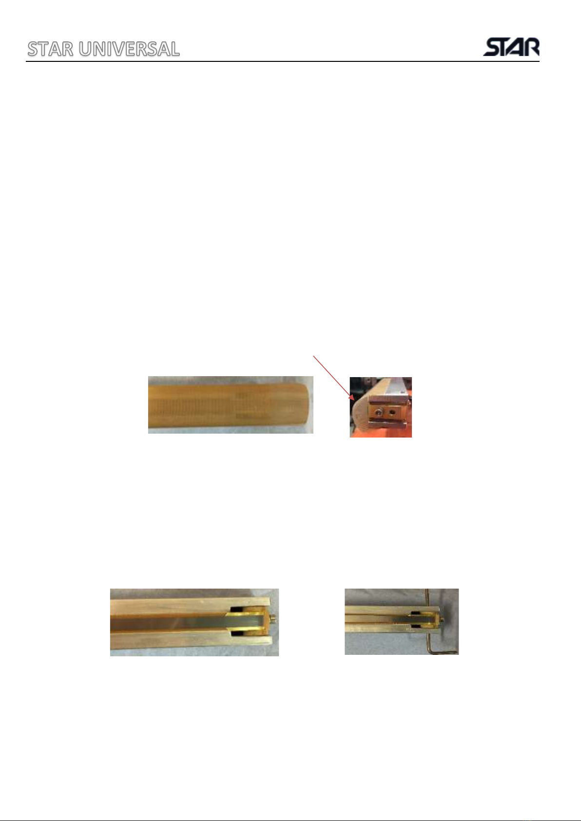
Barrier Tape: The barrier tape is a brown Teflon coated cloth designed to prevent plastic sticking
to the element ribbon. If this becomes burnt or damaged peel the old tape off, removing any
excess adhesive from the jaws. Take a length of new tape, remove one of the adhesive strips
and stick it to the front of the jaw, remove the other adhesive strip and stick to the back of the
jaw. The tape should be applied loosely so it is not in contact with the element ribbon when the
jaws are open.
Element Ribbon: Remove the barrier tape as above. Place the loading pins through the
expansion blocks and holes in either end of the jaw to keep the springs under compression and
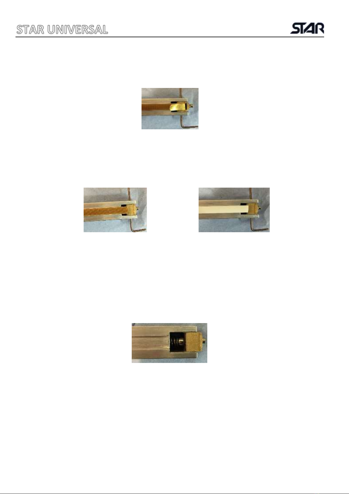
loosen the Allen key bolt. Remove the old ribbon. Cut a length of new element ribbon slightly
longer than the jaw and fold one end back on itself by about 5mm. Place this end in one of the
expansion blocks and tighten the Allen bolt. Measure the length of ribbon required to fit into
the other expansion block, cut to length and fold the end back 5mm. Fit in the other expansion
block and tighten the Allen bolt. Remove the loading pins and re-cover with barrier tape. Ensure
on double heat machines that the two elements line up to produce a good seal.
10
Brass Shim: Remove barrier tape and element ribbon as above. Remove the brass clamp by fully
unscrewing the Allen bolt. Replace the brass shim, attach the brass clamp and re fit the ribbon
and tape as above.
Silicone Rubber/Sponge –Heated Jaw: Remove the barrier tape and element ribbon as above.
Peel the silicone rubber away from the aluminium sealing jaw and clean any residual adhesive
left behind. Apply a NARROW bead of silicone adhesive to the channel, cut a piece of silicone
rubber to length and press into the channel ensuring a smooth surface. Replace the sealing
ribbon and barrier tape as above.
Clamp Bar Rubber: Remove the old barrier tape and rubber and clean the aluminium where it
was mounted. Apply a bead of silicone adhesive to the aluminium and stick the new rubber on.
Replace the barrier tapes over the rubber. To allow the adhesive to set fasten the top and
bottom clamp jaws together for around 2 hours.
Compression Spring and Ball Bearing: Remove barrier tape and element ribbon as above,
remove loading pin taking extra care due to the spring being under tension. Replace
Compression spring and ball bearing. Refit element ribbon and tape as above.

11
8 THERMOCOUPLE REPLACEMENT
Thermocouple: If the silicone has been replaced cut a shallow V in it just deep enough for the
thermocouple wire to sit flush with the rubber, the tip/disc should be sat on top of the rubber.
Place the thermocouple through the hole and fasten in place with thermocouple adhesive strip.
The tip of the thermocouple should be in the centre of the silicone. The backing tape should be
applied to cover the thermocouple.
1. Cut V shape into rubber:
2. Place thermocouple through hole in jaw:
3. Secure thermocouple using the thermocouple adhesive strip:
4. Place backing tape over length of rubber and replace the element ribbon:
12
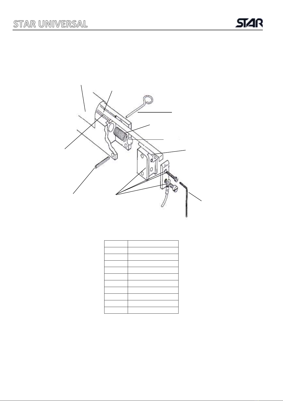
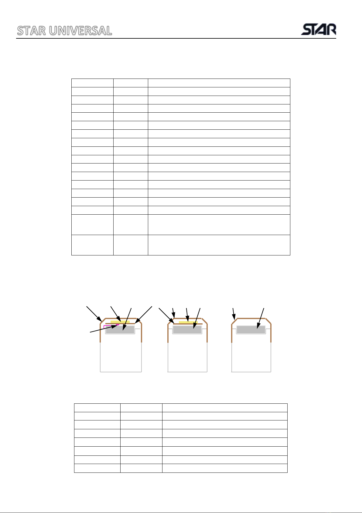
9 HEATED JAW TENSION ASSEMBLY
Diag No
Description
1
barrier tape
2
element ribbon
3
silicone rubber
4
Expansion block
5
Brass Shim
6
Compression spring
7
Ball bearing
8
25mm Roll Pin
9
Allen key
10
Loading pin
1
2
3
4
8
5
6
7
9
10
13
10 SERVICE REPLACEMENTS & JAW ASSEMBLIES
Part No
Diag No
Description
B018003
1
50mm barrier tape
E024002
2
6mm element ribbon
B017002
3
1m 9.5mm silicone rubber
M202005
4
15.5mm Expansion block (Pair)
M202004
5
9.5mm Brass Shim
B021005
6
Compression spring
B022002
7
Ball bearing
B023002
8
25mm Roll Pin
B029002
9
Allen key
M202009
10
Loading pin
B018007
NA
65mm barrier tape for fixed clamp jaw
B018022
NA
9mm PTFE backing tape
B017012
NA
D Section Silicone Sponge
B017014
NA
Silicone Rubber Compound (85g)
B029003
NA
Clamp Jaw allen key
S001001
NA
Spares Kit inc P&P
Comprises of 10m element ribbon, 10m barrier tape, 3m silicone
rubber/sponge & 1 tube silicone rubber compound
S001005
NA
Star 106 Spares Kit inc P&P
Comprises of 10m element ribbon, 10m 50mm barrier tape, 3m
silicone rubber, 3m D section sponge & 1 tube silicone adhesive
JAW ASSEMBLIES
HEATED JAW WITH HEATED JAW UNHEATED JAW
THERMOCOUPLE
Part No
Diag No
Description
B018003
1
50mm Barrier Tape
E024002
2
6mm Element Ribbon
B017002
3
9.5mm Silicone Rubber
B017007
4
9.5mm Silicone Sponge
B018022
11
9mm S/A Backing Tape
E019006
12
Thermocouple
B017014
NA
85g silicone rubber adhesive
1
1
2
2
3
11
3
12
4
1

14
11 ELECTRICAL PARTS LIST
Part No
Diag No
Description
E010001
E010036
SW1
On/Off Switch
Rocker Switch Cover IP65 (Stainless Steel model)
E017003
F2
Mains Fuse
E017008
F1
Solenoid Fuse
E003008
R1
Weld Relay
E022002
D1
Rectifier Diode
E021003
S
Supressor
E010005
E010006
SW2
Standard Foot Switch
Heavy Duty Foot Switch (Stainless Steel Model)
E011011
RS1
Safety Micro Switch
E005001
E005028
TH126
MKVI Controller
MKVI (C) Controller (MKVI C Model)
B014002
Membrane Keypad
E001001
TR1
Transformer
E002001
E002002
E002005
SOL
Solenoid Complete
Cone Solenoid Complete
Solenoid Plunger
E011014
SW3
Vacuum Pump Switch
P201001
VP
Vacuum Pump
E013005
E013006
SKT
3 Pin Socket
3 Pin Plug
B022001
Probe Roller Bush
B021004
Clamp Jaw Return Spring Right
B021008
Clamp Jaw Return Spring Left
P203006
Vacuum Regulator
P202001
Vacuum Gauge
M105008
Vacuum Probe
E019006
TC
Thermocouple (MKVI C Model)
E013016
Mains Lead & Plug
B021006
Solenoid Return Spring
M202007
Solenoid Pin
M102008
Brass Link
B016001
Jaw Arm Gaiter (Pair) (If IP rated)
ALL PARTS QUOTED IN THIS MANUAL ARE CORRECT
AT THE TIME OF PUBLICATION E&OE
STAR UNIVERSAL RESERVE THE RIGHT TO REVIEW
AND ALTER THE PARTS AS NECESSARY
COMPONENTS AND LAYOUT MAY VARY FROM THOSE PICTURED

15
SW1 ON/OFF SWITCH
SW2 TRIGGER
SW3 VACUUM PUMP SWITCH
SKT 3 PIN PLUG/SOCKET
VP VACUUM PUMP
R1 POWER RELAY
SOL SOLENOID
D1 DIODE
RS1 JAWS CLOSED MICRO SWITCH
TR1 MAIN TRANSFORMER
TH126 CIRCUIT BOARD
F1 SOLENOID FUSE
F2 MAIN FUSE
TC THERMOCOUPLE
N/A
STAR UNIVERSAL (GOSPORT) LTD
R1
12 WIRING DIAGRAMS
STAR 106 - 106C SOLENOID
(No connection 3 if it’s not a STAR 106C)
16
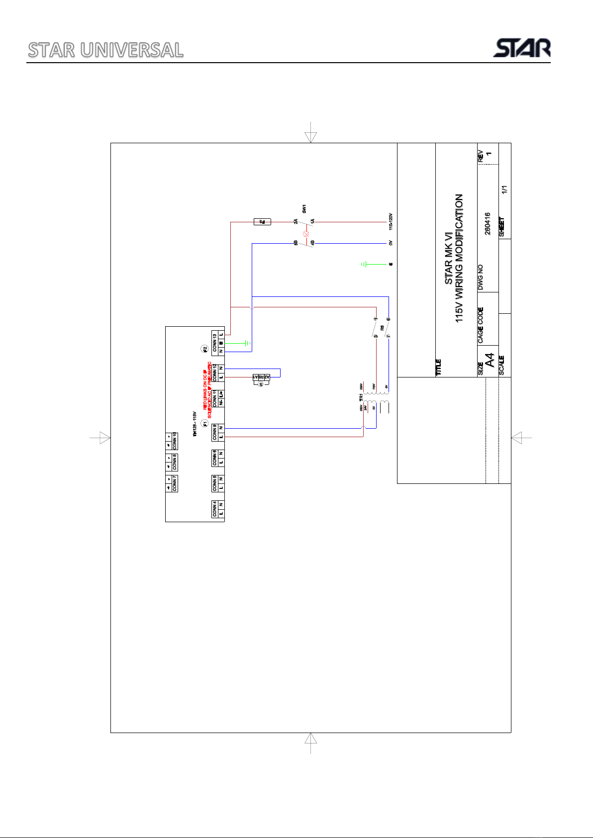
STAR 106 115V
F5 10a AS FUSE
R6 11 PIN RELAY 115V
S SUPPRESSOR
TH126 - 115V CONTROL BOARD 115V
N/A
STAR UNIVERSAL (GOSPORT) LTD
17
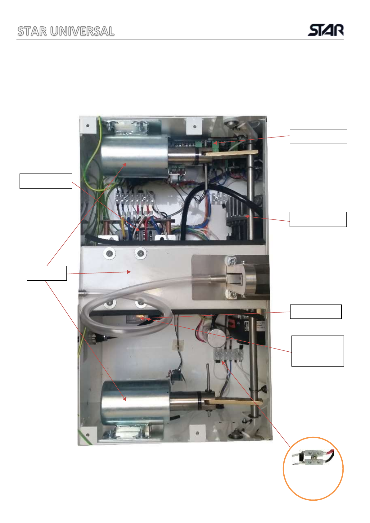
13 INSIDE THE MACHINE
STAR 106-106C
Transformer
Circuit Board
Solenoids
Power Relay
Vacuum Pump
Suppressor
across both
orange wires
Grey Strip on diode
to the red wire

18
14 TECHNICAL SPECIFICATION
STAR 106-106C
All the above weights and dimensions are approximate and based on the standard machine E&OE.
Star Universal reserves the right to change the above specifications without prior notice.
15 ENVIRONMENTAL RESPONSIBILITY
MACHINE RECYCLING
As this machine contains electrical and electronic components it must be disposed of correctly
and not in general land fill.
As Star Universal only build industrial equipment to individual customer requirements the
responsibility for the disposal lies with the end user.
Star Universal will offer a collection service for machines we have built at the end of their
useful life for recycling.
Please contact us for prices stating the machine model and serial number.
Producer Registration No. WEE/MM7018AA
Seal Length
500mm
600mm
750mm
900mm
Seal Width
6mm Standard, 2.5mm, 9.5mm 12.5mm and 20mm options
Jaw Opening
Solenoid approx. 30mm
Max Material thickness
1000µm approx. (4000g)
Sealing Cycle Time
Typically, 4-10s
Vacuum Cycle Time
Typically, 2-20s Dependent on size of pack and vacuum level required
Power Supply
230V 50/60Hz Single Phase, 115V Optional
Average Power Consumption / Cycle
0.02kWh
Average Power
Vacuum 160W, Weld 1730W, Cool 250W, Standby 25W
Jaw Length
565mm
665mm
815mm
965mm
Machine Body length
500mm
500mm
500mm
500mm
Depth
415mm
Overall Height
430mm
Weight Solenoid Machine
46kg
48kg
50kg
53kg

19
16 STAR UNIVERSAL WARRANTY POLICY
The Company provides a 1-year warranty from the date of delivery on all Star Heat Sealing
machines. If any part is found defective due to faulty manufacture, Star Universal will affect the
repair or replacement to the customer free of charge providing:
a) The fault is reported directly to the Service Department.
b) The fault is not caused by misuse, neglect or faulty adjustments by the operator.
c) The machine failure has not occurred through normal wear and application usage.
d) The machine has not been serviced or repaired by any person not authorised by Star
Universal during the warranty period.
e) The machine is returned to Star Universal at the address below.
Expendable items like the jaw barrier tape and heating elements are not covered by the
warranty but are readily available at a charge from the Service Department.
Travel time to attend a machine on site may be charged at the current applicable rates.
This warranty is additional to the normal customer statutory rights.

20
Star Universal (Gosport) Ltd
Unit 2, Clarence Wharf, Mumby Road, Gosport, Hampshire, United Kingdom, PO12 1AJ
Tel: + 44 (0) 23 9258 2857 Fax: + 44 (0) 23 9251 1731
Email: sales@staruniversal.com
Web: www.staruniversal.com
This manual suits for next models
1
Table of contents


