Star FL3X Media 100BASE-T1 User manual

FL3X Media 100BASE-T1
Instructions for Use

Created by STAR ELECTRONICS GmbH & Co. KG
Date created 2022-02-16 Date modified 2023-02-20 Page 2 of 19
3 -0093 -0A01 -D04_I nstruction_fo r_Use_FL3X_Media 1 00BASE-T1 _D1 V2-F .docx
Contact Information
STAR ELECTRONICS GmbH & Co. KG
A Company of the STAR COOPERATION Group
Jahnstraße 86
73037 Goeppingen
Phone: +49 (0)7031 6288-5656
Phone: +49 (0)7031 6288-5330 (Support)
Sales: sales-ee@star-cooperation.com
Support: support-ee@star-cooperation.com
www.flex-product.com
Company Data
STAR ELECTRONICS GmbH & Co. KG, registered offices: Göppingen, register court Ulm, HRA 721096
Partner liable to unlimited extent: STAR ELECTRONICS Verwaltungs-GmbH, registered offices: Göppingen, register
court Ulm, HRB 722565
Represented by the executive board: Rolf Wittig, Henning Lange
Copyright Notice
2023 STAR ELECTRONICS GmbH & Co. KG GmbH. All Rights Reserved.
No part of this document may be reproduced in any form (photocopy, microfilm or another procedure) without
prior written consent from STAR ELECTRONICS GmbH & Co. KG.
Trademarks
Any trademarks used in this document are the property of their respective owners.
Disclaimer
The information contained in this document does not affect or change General Terms and Conditions of STAR
ELECTRONICS GmbH & Co. KG.STAR ELECTRONICS GmbH & Co. KG does not guarantee the completeness and
accuracy of the content of this document and assumes no responsibility for any errors which may appear in this
document or due to this document. The content of this document or the associated products are subject to
change without notice at any time.
Based on currently state of arts and science it is impossible to develop software that is bug-free in all
applications. Therefore, the product is only allowed to be used in the sense of the product use case described
herein.
STAR ELECTRONICS GmbH & Co. KG makes no warranty express or implied, as to this document or the
information content, materials or products for any particular purpose, nor does STAR ELECTRONICS GmbH & Co.
KG assume any liability arising out of the application or use of this product, and disclaims all liabilities, including
without limitation resulting damages, as permissible by applicable law.
All operating parameters which are provided in this document can vary in different applications or over time. The
herein described product solely is allowed to be used as described in chapter “Intended use”.
Without limiting the rights under copyright, no part of this document may be reproduced, stored in or introduced
into a retrieval system, or transmitted in any form or by any means (electronic, mechanical, photocopying,
recording, or otherwise), or for any purpose, without the express written consent of STAR ELECTRONICS GmbH &
Co. KG.
STAR ELECTRONICS GmbH & Co. KG may have patents, patent applications, trademarks, copyrights, or other
intellectual property rights covering subject matter in this document. Except as expressly stated in a written
license agreement from STAR ELECTRONICS GmbH & Co. KG,the furnishing of this document does not give you
any license to these patents, trademarks, copyrights, or other intellectual property.

Created by STAR ELECTRONICS GmbH & Co. KG
Date created 2022-02-16 Date modified 2023-02-20 Page 3 of 19
3 -0093 -0A01 -D04_I nstruction_fo r_Use_FL3X_Media 1 00BASE-T1 _D1 V2-F .docx
Any semiconductor devices have an inherent chance of failure. You have to protect against injury, damage or loss
from such failures by incorporating safety design measures into your facility and equipment such as redundancy,
fire protection, and prevention of over-current levels and other abnormal operating conditions.
The safety and handling instructions in this document have to be followed strictly.
EC Conformity
The FL3X Media 100BASE-T1 complies with the essential requirements of the following applicable European
Community Directive(s) including current amendments, and carries the CE marking accordingly:
2014/30/EU EMC Directive
The following standard(s) have been used to assess the product:
EN 61000-4-2:2009
EN 61000-4-3:2006 + A1:2008 + A2:2010
EN 61000-4-4:2012
EN 61000-4-6:2014
EN 61000-6-2:2005
EN 61000-6-4:2007 + A1:2011
EN 61326-1:2013
The FL3X Media 100BASE-T1 is designed, intended and authorized for industrial use only. Using the product in
domestic environment may lead to electromagnetic disturbances.
This product is compliant with the European Community Directive 2011/65/EC on the restriction of the use of
certain hazardous substances in electrical and electronic equipment (RoHS).
UK Conformity
The FL3X Media 100BASE-T1 complies with the essential requirements of the following applicable UK Regulations
including current amendments, and carries the UK marking accordingly:
2016 Electromagnetic Compatibility Regulations
The following standard(s) have been used to assess the product:
EN 61000-4-2:2009
EN 61000-4-3:2006 + A1:2008 + A2:2010
EN 61000-4-4:2012
EN 61000-4-6:2014
EN 61000-6-2:2005
EN 61000-6-4:2007 + A1:2011
EN 61326-1:2013
The FL3X Media 100BASE-T1 is designed, intended and authorized for industrial use only. Using the product in
domestic environment may lead to electromagnetic disturbances.
This product is compliant with “the Restriction of the Use of Certain Hazardous Substances in Electrical and
Electronic Equipment Regulations 2012”.

Created by STAR ELECTRONICS GmbH & Co. KG
Date created 2022-02-16 Date modified 2023-02-20 Page 4 of 19
3 -0093 -0A01 -D04_I nstruction_fo r_Use_FL3X_Media 1 00BASE-T1 _D1 V2-F .docx
Revision History
Document number: 3-0093-0A01-D04
Version
Date
Description
D1V0-4 25-Jun-2018 Preliminary release
D1V0-F 23-Apr-2019 First release
D1V1-F 01-Feb-2022 Updated chapter EC Conformity
Added chapter UK Conformity
changed product pictures
D1V2-F 20-Feb-2023 Product name changed
Related Hardware / Software Versions
Product
Reference No.
Version
Remarks
FL3X Media 100BASE-T1 3-0093-A01-01 20 Old Product:
FL3X Media 100BASE-T1

Created by STAR ELECTRONICS GmbH & Co. KG
Date created 2022-02-16 Date modified 2023-02-20 Page 5 of 19
3 -0093 -0A01 -D04_I nstruction_fo r_Use_FL3X_Media 1 00BASE-T1 _D1 V2-F .docx
Contents
1General ..................................................................................................................................................6
1.1 Intended use........................................................................................................................................6
1.2 Used Pictograms..................................................................................................................................6
1.3 Safety and Handling Instructions..........................................................................................................6
1.4 User Group ..........................................................................................................................................7
1.5 Meaning of Text Styles .........................................................................................................................7
2Product Description ..............................................................................................................................8
2.1 FL3X Media 100BASE-T1 at a glance ....................................................................................................8
2.2 Accessory Parts ...................................................................................................................................8
3Technical Data.......................................................................................................................................9
3.1 Electrical Characteristics .....................................................................................................................9
3.2 Physical Characteristics .......................................................................................................................9
3.3 Environmental Conditions ....................................................................................................................9
3.4 Interfaces ............................................................................................................................................9
3.4.1 Power ..................................................................................................................................................9
3.4.2 Ethernet (RJ45) ..................................................................................................................................10
3.4.3 Status LED and DIP-switch .................................................................................................................11
3.4.4 2-Wire Ethernet (D-Sub) .....................................................................................................................11
4Getting Started................................................................................................................................... 13
4.1 Assembly and Line-up ........................................................................................................................13
4.2 Configuration and Operation ..............................................................................................................13
5Shipping, Maintenance and Disposal................................................................................................. 14
6Troubleshooting ................................................................................................................................. 15
7Ordering Information ......................................................................................................................... 16
7.1 FL3X Media 100BASE-T1....................................................................................................................16
7.2 Accessory Parts .................................................................................................................................16
7.3 Related Documents............................................................................................................................16
8Appendix............................................................................................................................................. 17
8.1 Appendix A: Guideline for handling ESD sensitive Products.................................................................17
8.2 Appendix B: .......................................................................................................................................17
8.2.1 Acronyms and Abbreviations ..............................................................................................................17
8.2.2 List of Tables .....................................................................................................................................17
8.2.3 List of Figures ....................................................................................................................................17

Created by STAR ELECTRONICS GmbH & Co. KG
Date created 2022-02-16 Date modified 2023-02-20 Page 6 of 19
3 -0093 -0A01 -D04_I nstruction_fo r_Use_FL3X_Media 1 00BASE-T1 _D1 V2-F .docx
1General
1.1 Intended use
The FL3X Media 100BASE-T1 is solely used to convert “100BASE-TX” into “100BASE-T1” and vice versa.
Only the herein described accessory parts are allowed to be used together with the FL3X Media 100BASE-
T1.
The FL3X Media 100BASE-T1 is designed, intended, and authorized only for laboratory applications use.
Any other use without the prior written consent of STAR ELECTRONICS GmbH & Co. KG prohibited.
The FL3X Media 100BASE-T1 is NOT designed, intended, or authorized for
use as part of medical systems,
life support applications,
aviation, space, nuclear, or military applications,
use in areas where combustible or explosive gas mixtures are likely to occur,
other applications in which a mistake or malfunction may result in death, personal injury or
severe physical damage.
The product described in this document is an industrial device, i.e. is designed, intended, or authorized for
professional use. It is not designed, intended, or authorized for home applications or consumers. For this
reason, use by non-professionals is forbidden.
1.2 Used Pictograms
The meaning of used pictograms is shortly described below.
Follow the specific instructions in the document where these pictograms are placed.
NOTICE
Used to indicate a situation which may result in an operating failure.
Damage of the product may occur, but there is no hazard of injury
if not avoided.
Information
Used to indicate information provided only for purposes of clarification, illustration, and
general information.
Reference
References to other documents.
Product marking which shows the compliance of the product with the European Waste
Electrical and Electronic Equipment Directive 2012/19/EU.
1.3 Safety and Handling Instructions
Please read the instructions for use carefully. To protect the device or the application against damage, or
to avoid personal injury the FL3X Media 100BASE-T1 has to be handled as described herein.
Changes or modifications of the FL3X Media 100BASE-T1 are not allowed for safety and warranty reasons!
STAR ELECTRONICS GmbH & Co. KG is not liable for any damages arising from non-observance of the
product information.
Follow the
a) specific safety and handling instructions placed at dedicated document positions
b) general safety and handling instructions below:

Created by STAR ELECTRONICS GmbH & Co. KG
Date created 2022-02-16 Date modified 2023-02-20 Page 7 of 19
3 -0093 -0A01 -D04_I nstruction_fo r_Use_FL3X_Media 1 00BASE-T1 _D1 V2-F .docx
NOTICE
To prevent damage to the FL3X Media 100BASE-T1, or consequential damages:
Do not open the FL3X Media 100BASE-T1.
Do not connect any other signals to the interfaces as described in the chapter
“Interfaces”. Ensure that all signals are within the specified range.
High temperatures can damage the FL3X Media 100BASE-T1. Keep the FL3X Media
100BASE-T1 away from heaters, stoves, fireplaces, and other sources of heat.
Do not expose the FL3X Media 100BASE-T1 to rain or use it near water.
Do not use the FL3X Media 100BASE-T1 in areas of explosion hazard.
The maximum allowed length of the power cable is 3m.
Do not use the FL3X Media 100BASE-T1 in DC power supply networks.
1.4 User Group
This document is written for expert technicians who are familiar with electronic components and systems.
Each person involved with assembly, line-up, operation, maintenance, or disposal of the FL3X Media
100BASE-T1 has to
be a qualified technician, or electrician, or engineer
strictly adhere to this manual
receive a briefing by an authorized person
1.5 Meaning of Text Styles
In this document filenames, are marked with a different text format.

Created by STAR ELECTRONICS GmbH & Co. KG
Date created 2022-02-16 Date modified 2023-02-20 Page 8 of 19
3 -0093 -0A01 -D04_I nstruction_fo r_Use_FL3X_Media 1 00BASE-T1 _D1 V2-F .docx
2Product Description
2.1 FL3X Media 100BASE-T1 at a glance
The FL3X Media 100BASE-T1 is a bidirectional 100 Mbit Ethernet converter between the 2-wire standard
100BASE-T1 and the 4-wire standard 100BASE-Tx.
The Broadcom BCM89810 transceiver is used for the 100BASE-T1 conversion.
•Master and slave feature selectable with DIP-switch
•RJ45 connector for Ethernet
•D-Sub 9 pin for 2 wire Ethernet
•Power supply range: 8 – 48 V
Field of application
•Testing
•Diagnostics
2.2 Accessory Parts
For further information about accessories for the FL3X Media 100BASE-T1 see chapter 7.2 Accessory
Parts.
NOTICE
Use only accessory parts from STAR ELECTRONICS GmbH & Co. KG listed in chapter 7.2
Accessory Parts to ensure proper function and for warranty reasons!
Other accessories without prior written consent of STAR ELECTRONICS GmbH & Co. KG
must not be used.

Created by STAR ELECTRONICS GmbH & Co. KG
Date created 2022-02-16 Date modified 2023-02-20 Page 9 of 19
3 -0093 -0A01 -D04_I nstruction_fo r_Use_FL3X_Media 1 00BASE-T1 _D1 V2-F .docx
3Technical Data
3.1 Electrical Characteristics
Supply voltage
Min. Typ. Max.
Operating +8.0 V - +48.0 V
Absolute maximum
(non-operating)
-60.0 V - +60.0 V
Supply current - operating Typ.: 80 mA; Max.: 140 mA
Table 1: Electrical characteristics
3.2 Physical Characteristics
Connectors RJ45, D-Sub 9
Weight approx.
145 g
Dimensions approx. L x W x H
92 * 65 * 28 mm
3
Table 2: Physical characteristics
3.3 Environmental Conditions
Temperature
Operating: -40°C – +85°C
Non-operating: -40°C – +85°C
Storage: -40°C – +85°C
Relative Humidity 0% – 90% r. H., non-condensing
Table 3: Environmental conditions
3.4 Interfaces
The FL3X Media 100BASE-T1 has a power cable, two connectors, a 2 pin DIP-switch and some LED’s. The
following figures show the position of each interface.
Figure 1: Side with Power and Ethernet
Figure 2: Side with 100BASE-T1
3.4.1 Power
The valid range of the power supply for the FL3X Media 100BASE-T1 is within 8 - 48 V DC. The power
supply input of the FL3X Media 100BASE-T1 is EMC and reverse protected.

Created by STAR ELECTRONICS GmbH & Co. KG
Date created 2022-02-16 Date modified 2023-02-20 Page 10 of 19
3 -0093 -0A01 -D04_I nstruction_fo r_Use_FL3X_Media 1 00BASE-T1 _D1 V2-F .docx
Internal voltage regulators generate the operating voltages out of this supply voltage.
NOTICE
The maximum allowed length of the power cable is 3m.
Do
not
use the FL3X Media 100BASE-T1 in DC power supply networks.
The green LED near the power cable shows the power supply status, if the LED is on, the power is OK.
Figure 3: Power cable and green power LED
Power cable
Pin
Signal Name
Description
1
GND
Ground signal
2
Uin
Power in allowed in the range from 8 – 48 V
Table 4: Power cable
3.4.2 Ethernet (RJ45)
The FL3X Media 100BASE-T1 support a 100BASE-TX (100 Mbit/s Ethernet) interface at the power
connector side. This connector supports only “100MBit/s full-duplex” mode.
NOTICE
The maximum allowed length of the Ethernet cable is 30m.
There are two LEDs near the RJ45 connector, a green LED and a yellow LED. The yellow LED shows the link
state. The green LED shows traffic.
Link
Active
Power

Created by STAR ELECTRONICS GmbH & Co. KG
Date created 2022-02-16 Date modified 2023-02-20 Page 11 of 19
3 -0093 -0A01 -D04_I nstruction_fo r_Use_FL3X_Media 1 00BASE-T1 _D1 V2-F .docx
Figure 4: Ethernet connector with yellow and green LED
Connector RJ45 (Ethernet)
Pin
Signal Name
Description
1
TP0+
Ethernet signal plus 0.
2
TP0-
Ethernet signal minus 0.
3
TP1+
Ethernet signal plus 2.
4
TP2+
Not needed (100 Mbit/s only)
5
TP2-
Not needed (100 Mbit/s only)
6
TP1-
Ethernet signal minus 1.
7
TP3+
Not needed (100 Mbit/s only)
8
TP3-
Not needed (100 Mbit/s only)
Table 5: Ethernet (RJ45) Connector
3.4.3 Status LED and DIP-switch
The FL3X Media 100BASE-T1 has a yellow Status LED at the power connector side.
Status LED
Description
blinking The device tries to establish a link at the 100BASE-TX connector.
permanently ON A link is established at the 100BASE-TX connector.
The DIP-Switch ‘1’ configures the 100BASE-T1 interface – it changes between Master or Slave function. If
the switch is up the transceiver is configured as Slave, if the switch is down it is configured as Master.
The DIP-Switch ‘2’ has no function (reserved).
Figure 5: Yellow status LED and DIP-switch
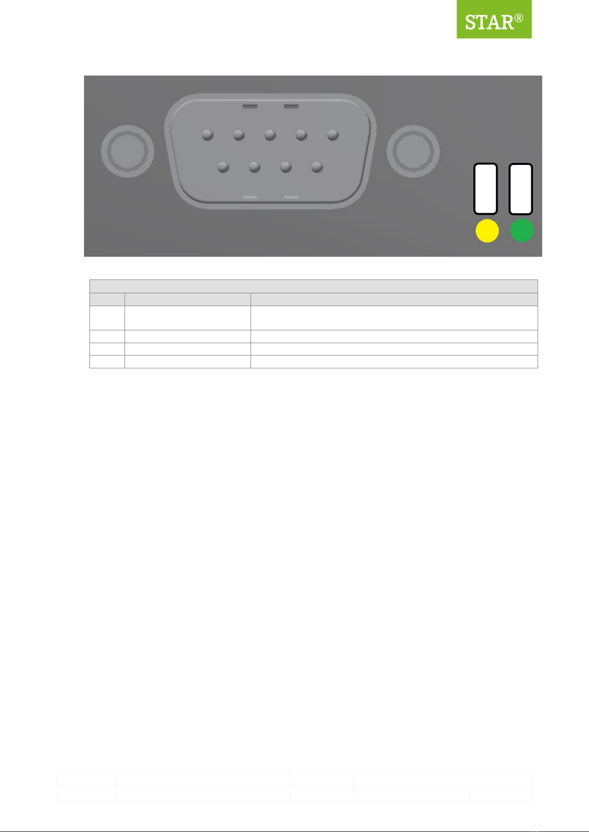
3.4.4 2-Wire Ethernet (D-Sub)
The FL3X Media 100BASE-T1 support a 100BASE-T1 interface.
There are two LEDs near the D-Sub connector: a green LED and a yellow LED. The yellow LED shows the
link state. The green LED shows traffic.
The following LED states are shown:
State
Link LED
Active LED
Description
No Link cyclically switching between
ON and OFF (period 2s)
permanently ON The device tries to establish a link.
Link permanently ON toggles between
ON and OFF
The active LED has inverted logic. If no
communication is present, the LED is
ON. Any communication switches the
LED OFF.
1
2
Status
Ma./Sl.
Res.
Created by STAR ELECTRONICS GmbH & Co. KG
Date created 2022-02-16 Date modified 2023-02-20 Page 12 of 19
3 -0093 -0A01 -D04_I nstruction_fo r_Use_FL3X_Media 1 00BASE-T1 _D1 V2-F .docx
Figure 6: 100BASE-T1 D-Sub connector with yellow and green LED
Connector DSub (100BASE-T1 2-wire ethernet)
Pin
Signal Name
Description
1, 2,
6 - 9
NC Not connected
3
ETH-GND
Ground for ethernet, connect over an inductor to internal ground.
4
ETH_BP
100BASE-T1 bus plus signal.
5
ETH_BM
100BASE-T1 bus minus signal
Table 6: Connector for DSub (2-wire ethernet)
Link
Active

Created by STAR ELECTRONICS GmbH & Co. KG
Date created 2022-02-16 Date modified 2023-02-20 Page 13 of 19
3 -0093 -0A01 -D04_I nstruction_fo r_Use_FL3X_Media 1 00BASE-T1 _D1 V2-F .docx
4Getting Started
4.1 Assembly and Line-up
Read and follow these instructions when connecting and using the FL3X Media 100BASE-T1:
NOTICE
Ensure that all signal lines connected to the FL3X Media 100BASE-T1 are in the
allowed range.
Be sure to connect all cables as described in this manual.
Never insert anything metallic into the openings of the FL3X Media 100BASE-T1.
Ensure to grasp the plug and not the cable when disconnecting the FL3X Media
100BASE-T1.
4.2 Configuration and Operation
Use the power cable of the FL3X Media 100BASE-T1 to connect with a power-supply within the correct
voltage range.
Connect the 100BASE-T1 and 100BASE-Tx with their networks. Check the pinouts.
Check the state of the LEDs. Adjust the DIP-Switch if necessary.

Created by STAR ELECTRONICS GmbH & Co. KG
Date created 2022-02-16 Date modified 2023-02-20 Page 14 of 19
3 -0093 -0A01 -D04_I nstruction_fo r_Use_FL3X_Media 1 00BASE-T1 _D1 V2-F .docx
5Shipping, Maintenance and Disposal
Dispose off properly per regulations of the country where end-of-life occurs.

Created by STAR ELECTRONICS GmbH & Co. KG
Date created 2022-02-16 Date modified 2023-02-20 Page 15 of 19
3 -0093 -0A01 -D04_I nstruction_fo r_Use_FL3X_Media 1 00BASE-T1 _D1 V2-F .docx
6Troubleshooting
This chapter contains some frequently asked questions about the FL3X Media 100BASE-T1.
1
Effect
No LINK at the 100BASE-T1 connector.
Solution
Check the DIP-Switch for correct Master/Slave configuration.
A 100BASE-T1 communication is a Point-to-Point- Connection where on
communication partner acts as ‘Master’ and one communication partner acts as
‘Slave’.
2
Effect
No LINK at the Ethernet connector.
Solution Check the “Link Speed & Duplex” settings of the connected network adapter. See
chapter 3.4.2 for supported configurations.

Created by STAR ELECTRONICS GmbH & Co. KG
Date created 2022-02-16 Date modified 2023-02-20 Page 16 of 19
3 -0093 -0A01 -D04_I nstruction_fo r_Use_FL3X_Media 1 00BASE-T1 _D1 V2-F .docx
7Ordering Information
7.1 FL3X Media 100BASE-T1
Product
Description
Ordering number
FL3X Media BASE100-T1 FL3X Media BASE100-T1 3-V0930A01
7.2 Accessory Parts
Product
Description
Ordering number
Customer specific parts
Please contact
STAR ELECTRONICS
GmbH & Co. KG
7.3 Related Documents
Document
Description
Ordering number
-

Created by STAR ELECTRONICS GmbH & Co. KG
Date created 2022-02-16 Date modified 2023-02-20 Page 17 of 19
3 -0093 -0A01 -D04_I nstruction_fo r_Use_FL3X_Media 1 00BASE-T1 _D1 V2-F .docx
8Appendix
8.1 Appendix A: Guideline for handling ESD sensitive Products
Any tester, equipment, or tool used at any production step or for any manipulation of semi-
conductor devices must have its shield connected to ground.
The product itself and the carrier system of the product respectively must be placed on a
conductive table top or covered by an antistatic surface (superficial resistivity equal to or higher
than 0.5MΩ/cm2), grounded through a ground cable (conductive cable from protected equipment to
ground isolated through a 1MΩ resistor placed in series).
All manipulation of finished goods has to be made at such a grounded worktable.
The worktable must be free of all non-antistatic objects.
An antistatic floor covering grounded through a conductive ground cable (with serial resistor
between 0.9MΩand 1.5MΩ) should be used.
It is recommended that you wear an antistatic wrist or ankle strap, connected to the antistatic floor
covering or to the grounded equipment.
If no antistatic wrist or ankle strap is worn, touch the surface of the grounded worktable before
each manipulation of the ESD sensitive product.
It is recommended that antistatic gloves or finger coats be worn.
It is recommended that nylon clothing be avoided while performing any manipulation of parts.
8.2 Appendix B:
8.2.1 Acronyms and Abbreviations
Item
Definition
BD Bus driver
BP Bus plus
BM Bus minus
ECU Electronic Control Unit
EMC Electromagnetic Compatibility
ESD
Electro Static Discharge
NC
Not Connected
PCB Printed Circuit Board
PL Physical Layer
8.2.2 List of Tables
Table 1: Electrical characteristics .........................................................................................................................9
Table 2: Physical characteristics...........................................................................................................................9
Table 3: Environmental conditions ........................................................................................................................9
Table 4: Power cable ..........................................................................................................................................10
Table 5: Ethernet (RJ45) Connector.....................................................................................................................11
Table 6: Connector for DSub (2-wire ethernet) ....................................................................................................12
8.2.3 List of Figures
Figure 1: Side with Power and Ethernet ................................................................................................................9
Figure 2: Side with 100BASE-T1............................................................................................................................9
Figure 3: Power cable and green power LED .......................................................................................................10
Figure 4: Ethernet connector with yellow and green LED.....................................................................................11
Figure 5: Yellow status LED and DIP-switch.........................................................................................................11

Created by STAR ELECTRONICS GmbH & Co. KG
Date created 2022-02-16 Date modified 2023-02-20 Page 18 of 19
3 -0093 -0A01 -D04_I nstruction_fo r_Use_FL3X_Media 1 00BASE-T1 _D1 V2-F .docx
Figure 6: 100BASE-T1 D-Sub connector with yellow and green LED.....................................................................12

Created by STAR ELECTRONICS GmbH & Co. KG
Date created 2022-02-16 Date modified 2023-02-20 Page 19 of 19
3 -0093 -0A01 -D04_I nstruction_fo r_Use_FL3X_Media 1 00BASE-T1 _D1 V2-F .docx
STAR ELECTRONICS GmbH & Co. KG
A Company of the STAR COOPERATION Group
Jahnstraße 86
73037 Goeppingen
Germany
Phone: +49 (0) 7031 6288-5656
sales-ee@star-cooperation.com
www.flex-product.com
Table of contents
Popular Network Hardware manuals by other brands


Alvarion
Alvarion BreezeACCESS II System manual

Solid State Logic
Solid State Logic HC Bridge SRC user guide

Paradyne
Paradyne COMSPHERE 3610 installation instructions

AirTouch
AirTouch U250 owner's manual

Balluff
Balluff Easy Tool-ID BSG TID-05-T30-00-005 Installation and operation

Oracle
Oracle Acme Packet 3900 Hardware installation and maintenance guide

LanReady
LanReady AP-952X user manual

Arlotto
Arlotto ANVR832 user manual

Ubiquiti
Ubiquiti UniFi Cloud Key Gen2 Plus manual

Digi
Digi NetSilicon Connectware Connect Series user guide

Memotec
Memotec NetPerformer SDM-9220 Series Hardware installation guide

Ruckus Wireless
Ruckus Wireless Media Flex 2200 Series manual