StarDot Technologies NetCam SC User manual
NetCam SC
Va n d a l Re s i s t a n t do m e
User’s Manual
www.stardot.com


NetCam SC Vandal Resistant Dome

NetCam SC Vandal Resistant Dome
Table of Contents
Chapter 1 Conguration....................................................................7
1.1 Before You Start.................................................................7
1.2 What’s Included and What’s Required ...............................7
1.3 Parts of NetCam SC ..........................................................8
1.4 Connecting NetCam SC to a Network ...............................9
1.5 An Overview of Network Connectivity................................9
Chapter 2 Installation ...................................................................... 11
2.1 Installing NetCam SC....................................................... 11
2.2 Installing NetCam SC to Pipe/Wall/Ceiling.......................12
2.3 Installing NetCam SC Bottom to a Pipe ..........................14
2.4 Installing NetCam SC Side to a Pipe ...............................15
2.5 Installing NetCam SC Side to Ceiling ..............................16
2.6 Installing NetCam SC Side to Wall...................................17
2.7 Removing the Internal Camera Assembly........................18
2.8 Resetting Camera ............................................................19
2.9 Connecting Serial Port Cable (RS-232) to Camera .........20
Chapter 3 Accessing NetCam SC ..................................................22
3.1 Viewing NetCam SC’s Images .........................................22
3.2 NetCamSC’sCongurationMenus .................................23
3.3 Image Properties..............................................................24
3.4 Overlay Properties ...........................................................34
3.5 FTP Properties .................................................................38
3.6 Date/Time Properties .......................................................43
3.7 Network Properties ..........................................................46
3.8 Dial-Out Properties ..........................................................49
3.9 Security Properties...........................................................52
3.10 AdvancedMenus .............................................................53
3.11 Miscellaneous ..................................................................54
3.12 ManualCong..................................................................54
3.13 PTZ ..................................................................................54
3.14 Dynamic DNS...................................................................55
3.15 Trigger Properties ............................................................56

NetCam SC Vandal Resistant Dome
Technical Support .............................................................................61
Specications ....................................................................................63

NetCam SC Vandal Resistant Dome

NetCam SC Vandal Resistant Dome Page 7
Chapter 1 Conguration
Congratulations on your purchase of a StarDot NetCam SC Dome network
camera with integrated web server. The NetCam SC Dome combines the best
of the analog CCTV world (auto iris, mechanical day/night IR lter*, video out,
24VAC/12VC power inputs) with the best of the digital IP camera world (up to
5 megapixel, Power over Ethernet, integrated video motion detection).
With proper usage, the NetCam SC Dome will provide many years of quality
video. We recommend that you read this manual carefully to completely
understand the camera’s capabilities. Throughout this manual, your NetCam SC
Dome camera will also be referred to as simply NetCam SC.
* Mechanical Day/night IR lter available only on IR models.
1.1 Before You Start
This manual guides you through the basic setup procedure for the
NetCam SC and provides a detailed resource of the camera’s advanced
options and capabilities.
1.2 What’s Included and What’s Required
The basic package includes:
NetCam SC, lens, StarDot Tools CD and Manual, L-wrench, •
Gasket, Wall Mount Screws with anchors, Dome Case Screws with
O-ring, and Mounting Template.
Since the NetCam SC is a PoE device (Power over Ethernet), it is
assumed that most users will provide their own CAT 5 or CAT 6 cable,
as well as a PoE switch or power injector. StarDot optionally offers a
wall mount, a power supply, a combination network/power cable and
a null serial conguration cable. In order to use the NetCam SC, you
will need the following:

Page 8 NetCam SC Vandal Resistant Dome
• Power source (PoE, 12VDC or 24VAC)
• A computer – for conguring NetCam SC and for viewing video
Note: A computer is not necessary to operate NetCam, only to congure it.
• Network connectivity (LAN, cable modem, DSL, T-1, Dial-Up
Internet Account, Satellite Modem, etc.)
1.3 Parts of NetCam SC
NET (PoE) 802.3af
100Mbit Power over Ethernet Port
PWR (DCPower Jack)
10-20VDC
VIDEO OUT
Analog Video
(NTSC or PAL)
24VAC
Useful for legacy CCTV
Power Infrastructure

NetCam SC Vandal Resistant Dome Page 9
1.4 Connecting NetCam SC to a Network
The StarDot Tools software can be used to nd the camera’s IP
address or to congure the camera with the Setup Wizard (optional).
Install the StarDot Tools software by inserting the CD-ROM and
running setup.exe (it should run automatically).
Connect NetCam SC into a PoE switch or injector with a
standard CAT 5 network cable or with a StarDot Combo
Ethernet/Power Cable.
If your network has a router or server that automatically assigns
IP addresses (DHCP), StarDot Tools will nd the camera’s IP
address and display it in the software. To access NetCam SC,
simply double-click its IP address. If the IP address is displayed,
skip to Chapter 3.
If no DHCP server is present, the NetCam SC will auto assign
itself a “zeroconf” IP address, which will always start with
169.254. You can temporarily assign your computer a similar
address and use StarDot Tools to nd the camera’s IP address
and assign it a new permanent IP address. To do so, give your
PC the IP address 169.254.100.100 with a subnet of 255.255.0.0.
1.5 An Overview of Network Connectivity
A LAN or network connection is the simplest configuration
for NetCam SC. NetCam SC simply needs an IP address (and other
networking parameters) to make the live images and conguration
menus accessible from any web browser on the network. There are
two ways NetCam SC can be assigned an IP address: automatically
or manually.

Page 10 NetCam SC Vandal Resistant Dome
Automatic IP Assignment (DHCP)
NetCam SC is shipped in an automatic IP assignment mode called
DHCP (Dynamic Host Conguration Protocol). If your network has a
DHCP server (in most cases, a router), it will automatically assign the
necessary network parameters to NetCam SC. Before you can access
the camera, you will need to know which IP address was assigned. Use
the StarDot Tools software to nd the camera’s IP address.
Automatic IP Assignment (zeroconf)
If no DHCP server is present, the NetCam SC will automatically
assign itself a “zeroconf” IP address, which will always start with
169.254. You can temporarily assign your computer a similar address
and use StarDot Tools to nd the camera’s IP address and assign it
a new permanent IP address. To do so, give your PC the IP address
169.254.100.100 with a subnet of 255.255.0.0. Use the StarDot Tools
software to nd the camera’s IP address.
Manual IP Assignment
If you want to assign the camera a permanent IP address, you will
need the following information:
• IP Address (example: 192.168.1.5)
• Subnet Mask (example: 255.255.255.0)
• Gateway (example: 192.168.1.1)
• DNS Servers (obtain from ISP)
If you are installing the camera on a company network, you will probably
want to get this information from the system administrator.
If NetCam SC is connected to a network with a DHCP server and
your computer is not running Windows, you can log into your router (or
whatever is acting as your DHCP server) and view the DHCP clients
table. NetCam SC will have a MAC address starting with 00:30:F4.
Take note of the IP address and enter it in your web browser. Click on
the conguration link, visit the network tab and assign the camera a
manual IP address (outside of the router’s DHCP range).

NetCam SC Vandal Resistant Dome Page 11
Chapter 2 Installation
Before installing the camera in its nal location, it is important to
congure and test it rst (see Chapter 1).
2.1 Installing NetCam SC
Measure the distance from the camera to the nearest Ethernet hub
or switch. This distance should not exceed 330 feet (100 meters). If you
wish to extend the distance further than 330 feet (100 meters), you can
add an Ethernet hub or switch.
Choose the optimal location for your NetCam SC. Make sure •
that the location you choose can withstand approximately 12.6
lbs (5.7 kg).
During the installation process, allow ample room for the wiring•
to avoid jamming the wires or stripping the wire insulation, as this
may cause an electrical and/or re hazard.
During installation, items may fall and cause damage or injury.•
Make sure to create a safe work environment by clearing your work
area from all nonessential items and personal.
There are three ways to power NetCam SC. This allows you go
install the camera in virtually any existing infrastructure. NOTE: Only
use one method to power the camera. Do not plug two or more power
sources into the camera simultaneously.
Power over Ethernet (PoE)
Run standard CAT 5 or better Ethernet cable from a PoE hub/
switch (or PoE power injector) into the NET jack on the back of
NetCam SC. NetCam SC will run off the PoE power running in the
CAT 5 cable. No other power source is required.

Page 12 NetCam SC Vandal Resistant Dome
Separate Ethernet and Power
If you decide not to use PoE, you can connect one end of a CAT
5 or better Ethernet cable into a hub/switch and the other end into the
NET jack on the back of NetCam SC. Plug a 12VDC 1A power supply
into the back of NetCam SC (or you may use a 24VAC power supply
and connect it to the input marked 24VAC).
StarDot’s Power/Network Cable
If you choose not to power NetCam SC via PoE and you still want the
take advantage of a single cable run, StarDot provides Power/Network
cable that allows you to run both power and data in the same cable. Visit
http://www.stardot.com for more information.
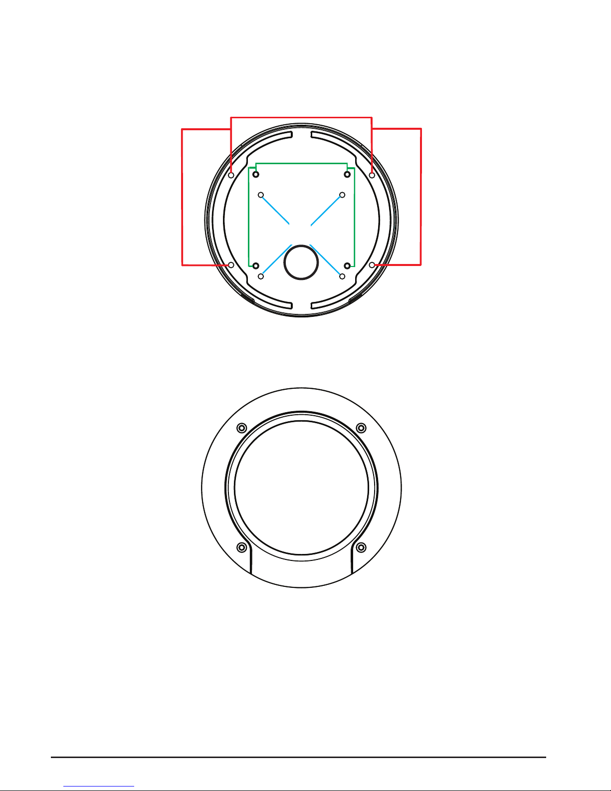
2.2 Installing NetCam SC to Pipe/Wall/Ceiling
NOTE: To maintain IP66 weatherproong, make sure to close up all unused
mounting holes with the provided screws and O-rings.
Use the shown holes [A] in gure 1 if you are mounting the dome •
directly to a ceiling or wall.
Use the shown holes [B] in gure 1 if you are mounting the •
dome directly to a wall mount adapter (Wall mount adapter not
included).
Use the shown holes [C] in gure 1 if you are mounting the dome •
directly to a junction box (Junction box and gasket not included).
NetCam SC Vandal Resistant Dome Page 13
A
C
B
Figure 1
1
2
3
4
Figure 2
(Screw Pattern)

Page 14 NetCam SC Vandal Resistant Dome
2.3 Installing NetCam SC Bottom to a Pipe
NOTE: To maintain IP66 weatherproong, make sure to close up all unused
mounting holes with the provided screws and O-rings.
Remove the cap bolt and O-ring (if installed) by using a coin or •
slotted screw driver and pass the desired wiring through the back
of the dome.
Connect the desired wiring and pull the wires through and into•
the pipe.
Thread the dome onto the pipe. Make sure to completely cover •
the pipe threads with Teon tape to maintain weatherproong.
During the installation of the dome onto the pipe, make sure•
that the wiring does not get stuck to the Teon tape, as this may
cause unnecessary damage to the wires and/or dome circuitry.
Once the dome is secured to the pipe, you can adjust the direc-•
tion and focus of the lens.
To adjust the lens, remove the dome cover by undoing the four•
cover screws with the supplied L-wrench.
Adjust the lens by pointing it in the desired direction. Use cau-•
tion while adjusting the lens as the lens assembly will pan and
tilt with little effort. Using excessive force may cause damage to
the lens assembly.
Adjust the focus by rotating the lens focusing mechanism until•
the desired focus is achieved. Depending on the type of lens
used, you may need to loosen and then tighten the lens locking
screw to complete this process.
Once you have nalized your adjustments, reassemble the dome •
cover by reinstalling the four bolts with the provided L-wrench.
To maintain IP66 weatherproong, make sure to securely tighten
the bolts so that there is little to no gap between the dome cover
and dome base. For an easier installation, tighten the screws by
using a crisscross screw pattern as shown in Figure 3.

NetCam SC Vandal Resistant Dome Page 15
2.4 Installing NetCam SC Side to a Pipe
NOTE: To maintain IP66 weatherproong, make sure to close up all unused
mounting holes with the provided screws and O-rings.
Remove the side mounted cap bolt and O-ring (if installed) by •
using a coin or slotted screw driver.
Pass the wiring assembly through the side pipe hole.•
Close the bottom wire hole with the cap bolt and O-ring that was •
removed from the side mounted pipe hole.
Connect the desired wiring and pull the wires through and into•
the pipe.
Thread the dome onto the pipe. Make sure to completely cover •
the pipe threads with Teon tape to maintain weatherproong.
During the installation of the dome onto the pipe, make sure•
that the wiring does not get stuck to the Teon tape, as this may
cause unnecessary damage to the wires and/or dome circuitry.
Once the dome is secured to the pipe, you can adjust the lens and•
focus.
To adjust the lens, remove the dome cover by undoing the four•
cover screws with the supplied L-wrench.
Adjust the lens by pointing it in the desired direction. Use cau-•
tion while adjusting the lens as the lens assembly will pan and
tilt with little effort. Using excessive force may cause undo
damage to the lens assembly.
Adjust the focus by rotating the lens focusing mechanism until•
the desired focus is achieved. Depending on the type of lens
used, you may need to loosen and then tighten the lens locking
screw to complete this process.
Once you have nalized your adjustments, reassemble the dome •
cover by reinstalling the four bolts with the provided L-wrench.
To maintain IP66 weatherproong, make sure to securely tighten
the bolts so that there is little to no gap between the dome cover
and dome base. For an easier installation, tighten the screws by
using a crisscross screw pattern as shown in Figure 2.

Page 16 NetCam SC Vandal Resistant Dome
2.5 Installing NetCam SC Side to Ceiling
NOTE: To maintain IP66 weatherproong, make sure to close up all unused
mounting holes with the provided screws and O-rings.
Attach the provided template to the desired mounting area.•
Drill a hole 5 mm in diameter and at least 35 mm in depth.•
Insert the plastic screw anchor provided. Repeat for all four•
mounting holes.
Connect the desired cables and make sure that they will not get•
caught or damaged during the installation process.
Remove the dome cover by undoing the four cover screws with•
the supplied L-wrench.
Mount the dome onto the ceiling by using mounting holes [A] •
as shown in Figure 1. If you are drilling a wiring hole in the
ceiling/wall, make sure that the hole diameter is within 30 mm.
To maintain IP66 weatherproong, make sure to also use and
correctly align the provided gasket with the hole to insulate the
ceiling/wall and dome base.
Once the dome is secured to the ceiling/wall, you can adjust the•
lens and focus.
To adjust the lens, remove the dome cover by undoing the four•
cover screws with the supplied L-wrench.
Adjust the lens by pointing it in the desired direction. Use cau-•
tion while adjusting the lens as the lens assembly will pan and
tilt with little effort. Using excessive force may cause undo
damage to the lens assembly.
Adjust the focus by rotating the lens focusing mechanism until•
the desired focus is achieved. Depending on the type of lens
used, you may need to loosen and then tighten the lens locking
screw to complete this process.
Once you have nalized your adjustments, reassemble the dome •
cover by reinstalling the four bolts with the provided L-wrench.
To maintain IP66 weatherproong, make sure to securely tighten
the bolts so that there is little to no gap between the dome cover
and dome base. For an easier installation, tighten the screws by
using a crisscross screw pattern as shown in Figure 2.

NetCam SC Vandal Resistant Dome Page 17
2.6 Installing NetCam SC Side to Wall
NOTE: To maintain IP66 weatherproong, make sure to close up all unused
mounting holes with the provided screws and O-rings.
Since the NetCam SC uses a two axis gimbal, we recommend
using a wall mount (Part Number: MNT-VWAL) for this type of wall
installation. (Wall Mount is not included)
Follow Wall Mount instructions to install wall mount (Part Num-•
ber: MNT-VWAL).
Connect the desired cables and make sure that they will not get•
caught or damaged during the installation process.
Remove the dome cover by undoing the four cover screws with•
the supplied L-wrench.
Mount the dome onto the ceiling by using mounting holes [A] •
as shown in Figure 1. If you are drilling a wiring hole in the
ceiling/wall, make sure that the hole diameter is within 30 mm.
To maintain IP66 weatherproong, make sure to also use and
correctly align the provided gasket with the hole to insulate the
ceiling/wall and dome base.
Once the dome is secured to the ceiling/wall, you can adjust the•
lens and focus.
To adjust the lens, remove the dome cover by undoing the four•
cover screws with the supplied L-wrench.
Adjust the lens by pointing it in the desired direction. Use cau-•
tion while adjusting the lens as the lens assembly will pan and
tilt with little effort. Using excessive force may cause undo
damage to the lens assembly.
Adjust the focus by rotating the lens focusing mechanism until•
the desired focus is achieved. Depending on the type of lens
used, you may need to loosen and then tighten the lens locking
screw to complete this process.
Once you have nalized your adjustments, reassemble the dome •
cover by reinstalling the four bolts with the provided L-wrench.
To maintain IP66 weatherproong, make sure to securely tighten
the bolts so that there is little to no gap between the dome cover
and dome base. For an easier installation, tighten the screws by
using a crisscross screw pattern as shown in Figure 2.

Page 18 NetCam SC Vandal Resistant Dome
2.7 Removing the Internal Camera Assembly
Removing the internal camera assembly will give you access to
the internal mounting holes [B,C] shown in Figure 1 and the interior
of the dome base area. The internal camera assembly does not need to
be removed to access the internal mounting holes for [A].
Remove the dome cover by undoing the four cover screws with•
the supplied L-wrench.
Locate and unscrew the two screws on the internal camera as-•
sembly connecting it to the base as shown in Figure 4. Do not
detach the screws from their base.
Locate the two plastic tabs shown in • Figure 4. Gently push them
towards the center of the dome as shown in Figure 4 and pull
the internal camera assembly away from the base to nalize the
removal process.
To reinstall the internal camera assembly, line up the internal•
camera assembly with the proper mounting holes and gently
push it into the dome base until the plastic tabs click into place.
Retighten the two screws. Do not over tighten as this may crack•
the mounting holes on the internal camera assembly.
Reassemble the dome cover by reinstalling the four bolts with•
the provided L-wrench. To maintain IP66 weatherproong,
make sure to securely tighten the bolts so that there is little to no
gap between the dome cover and dome base. For an easier in-
stallation, tighten the screws by using a crisscross screw pattern
as shown in Figure 2.
Figure 4
Tab Tab
Screw
Screw

NetCam SC Vandal Resistant Dome Page 19
2.8 Resetting Camera
You can reset the camera to the original factory setting by
depressing and holding the reset button found inside the camera as
shown in Figure 5 and Figure 6.
Figures 5 and 6

Page 20 NetCam SC Vandal Resistant Dome
2.9 Connecting Serial Port Cable (RS-232) to
Camera
Remove the dome cover by undoing the four cover screws with•
the supplied L-wrench.
Locate and unscrew the two screws on the internal camera as-•
sembly connecting it to the base as shown in Figure 4. Do not
detach the screws from their base.
Locate the two plastic tabs shown in • Figure 4. Gently push them
towards the center of the dome as shown in Figure 4 and pull
the internal camera assembly away from the base to nalize the
removal process.
Locate the serial port connector shown in Figure 7.•
Figure 7
Other manuals for NetCam SC
2
Table of contents
Other StarDot Technologies Security Camera manuals


