STARGAZER Wake Edition User manual

2/14/2023
StarGazer - Wake Edition
Mechanical
v.9
October 2021

2/14/2023
Table of Contents
Page No.
Section 1 Using StarGazer Wake Edition 1
Wakeboard Speed Mode 1
Section 2 Using RPM Mode 3
Section 3 Using Slalom Mode 4
Course Timing (No Mag Timing) 4
Section 4 Using Name List 6
Section 5 Additional Features/Background Settings/System Info. 7
Screen Contrast / Backlight 7
Setting Clock / Time Zone 7&11
Switch to MPH<>KPH (User Settings) 7
Compass Settings 12
Section 6 Driving Tips 8
Section 7 Troubleshooting/General Information 9
Section 8 Installation 13
Section 9 GPS Receiver 16

1
Section 1 INITIAL SYSTEM SET UP
The very first time your PerfectPass is turned on, it may ask you two questions:
1. “Initial Hours 000”. If this hour meter feature is present, use the UP Key to enter
the number of hours on your boat. PerfectPass will start counting from that
position. Press MENU Key to continue.
2. [ Read in MPH ^ = Yes ] If you want your system to display in MPH, press the
Up Key. For metric, press the Down Key.
USING STARGAZER WAKE EDITION
There are three operating modes to choose from: (1) Wakeboard/Wake Surf Mode is
speed based and controls from the GPS Sensor; (2) RPM Mode allows the user to set an
RPM value; and (3) Slalom Mode allows slalom skiers to enter a speed for open water
skiing and course skiing.
The ON/OFF key is pressed to turn control ON or OFF. System should always be in OFF
mode when not in use. Turning system ON or OFF is always done at neutral or at idle for
safety. You may be asked to confirm you are in neutral as follows [ IN NEUTRAL ^ =
Yes ]. Press UP Key to confirm.
Wakeboard Mode/Wake Surf (Speed Based)
Menu Arrow
Name/Mode
SETPOINT
Speed Base
Speed
Tachometer
Mode Indicator

2
When system is ON, the screen will appear as above with set point speed at left. By using
Menu Key you can move around the screen and highlight set point to make speed
changes.
Once desired speed has been set, you can simply pull up the rider and when set point has
been reached or exceeded the system will engage and take over automatically. (You will
hear an audible beep and “WAKEBOARD” heading will become highlighted to confirm
engagement.
To disengage system, pull back on the throttle.
The key to good driving is to smoothly drive to engagement speed so PerfectPass can
seamlessly take control. If you have a heavily laden boat and need full throttle from start,
slowly pull back on handle as speed increases to help PerfectPass engage smoothly.
If the rider falls, pull throttle back and system will disengage. Return slowly to rider and
pull them back up. PerfectPass will once again engage when set speed is reached.
Menu Arrow – To move to another mode, use menu key to highlight Menu arrow in
upper right corner and press up key to confirm. The following screen will appear with
other operating modes you can select.
KDW Adjustable Pull Parameter – This background setting allows you to tailor the
pull characteristics. To access, highlight Menu Key , and press the DOWN Key to
access this KDW screen: (NOTE: Most users will not need to adjust KDW).
KDW (Throttle Pull Rate) – KDW can be changed using up or down keys. The higher
the value, the more aggressive the control. Factory setting is about 80. Normal range is
40 – 100. (If this value is set too high, the control may become a little erratic and
engagement may not be as smooth). Some boats may need a lower value if control is not
smooth.
Down Key for
access to KDW
Use MENU Keyto
highlight desired Mode
and press UPKey
UP Keyto
selectMode

3
Section 2 RPM MODE
USING RPM MODE
In this mode, the screen will appear as follows:
Operating in this mode is very similar to using the Wakeboard mode, except the system is
now controlling to an RPM SETPOINT.
RPM DRIVING
Prior to towing the rider / skier, select the RPM SETPOINT by using the UP or DOWN
keys with the SETPOINT highlighted on the screen. Pull the rider up smoothly and
continue to accelerate up to or beyond the RPM SETPOINT so the system can engage
and take control. The digital tachometer should match the RPM set point.
Changes can be made to the RPM SETPOINT while the system in engaged (“on the fly”)
to fine-tune the RPM you desire.
2. Menu Arrow
1. SETPOINT
Speed Base
Speed
Tachometer
Mode Indicator

4
Section 3 SLALOM MODE
1. Select Slalom Mode. Simply set your speed and go.
2. If you wish to time your passes in a slalom course, you must “MAP”
the course.
3. You can select speeds in 1 mph (1.5 kph) increments. The official
speeds in MPH are: 24.9, 26.7, 28.6, 30.4, 32.3, 34.2, 36.0
4. The only adjustment to the pull is a value called “Pull Factor” found
by highlighting the Menu Arrow > in upper right corner, then press
UP KEY. The word SLALOM is now highlighted, press DOWN
KEY for “Pull Factor”. Standard is 50, a higher value is more
aggressive. (Range is 25–100). We do not expect that you will need
to adjust this.
5. Timing – If you “MAP” your course, the screen will show your Ball 3
and full course times as you exit the course.
Wake Edition - Course Mapping (No Magnet Timing)
Step. 1 Locate “Map Courses” on your screen.
Highlight the arrow and press DOWN Key.
Step. 2 You will see where you have the ability to Map Three (3) Courses. To
enter the coordinates for the first course highlight line 1. Press the UP
Key to select Course 1.
Use MENU KEY to highlight the course
you wish to map & press UP to select.
5
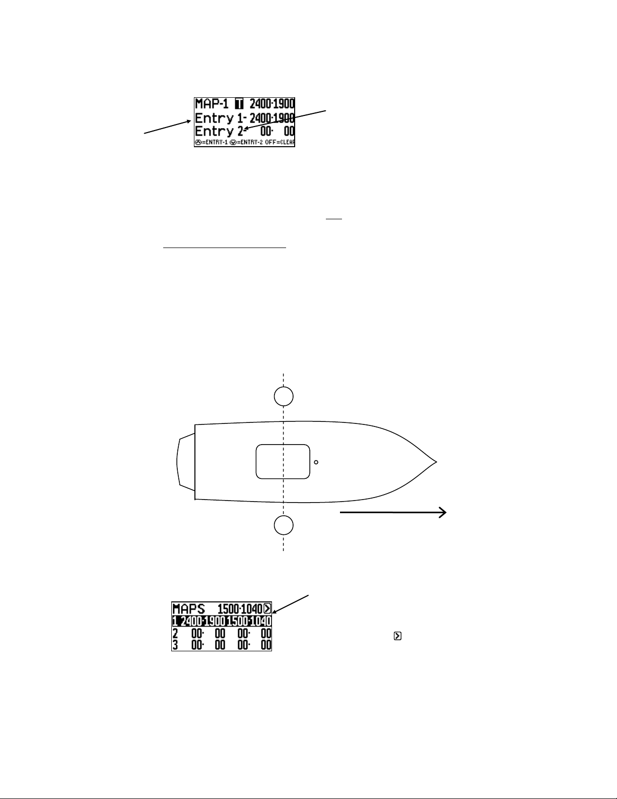
UP Key at DOWN Key at Entrance in opposite
Entrance direction (Entry 2)
(Entry 1)
Note: Only the entrance gates from each direction will be “mapped”.
Step. 3 Starting at one end of the course, idle the boat towards and through the
entrance gates. As you pass through the gates and the gate buoys are
parallel to the engine box, press the UP KEY. (Entry 1) The display will
beep to confirm coordinates are locked. (See Figure A).
Drive to the other end of the course, turn boat around and idle back
through the entrance gates into the course and press the DOWN KEY
(Entry 2) as the gate buoys pass the engine box. The display will beep.
(If you made an error you can simply repeat the procedure, press the UP
or DOWN KEY again and it will overwrite the original coordinates).
Figure A
Course #1 is now mapped and you are finished.
Use MENU Key to proceed.
MENU Arrow
To leave this screen, use MENU Key to
highlight MENU arrow and press UP Key.
If you wish to Map another course, highlight course #2 and press UP. Repeat procedure.
E
E
6
Section 4 USING NAME LIST
Additional PerfectPass features are accessed by pressing the MENU & UP keys together.
The features available vary depending on the make and model of your boat. If a feature
is not present on your PerfectPass then it is not available on your system. To move to the
next feature press the MENU key.
NAME LIST
This version of PerfectPass allows you to store up to four names and their preferred
speed. The Name List can be accessed by pressing the UP key when the NAME/MODE
section is highlighted or by going into the SUBMENU and selecting the Name List.
Once in the Name List press the MENU key to move through the list. With the desired
name highlighted press the UP key to select the name from the list and load their settings
or press the DOWN key to edit the name.
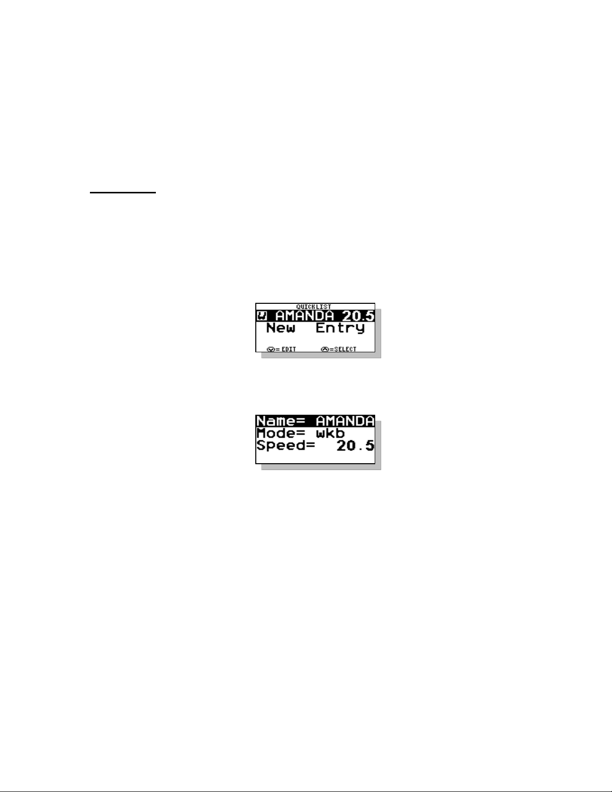
Creating Names – First enter the Quick List. Press the MENU key until [NEW
ENTRY] is highlighted. Then press the UP key to enter a new name. The following
screen will then appear:
Scroll through the alphabet using UP & DOWN keys, and then press MENU to move to
next position. Press the MENU key to move through the settings. If you are
programming a JUMP or SLALOM name there will be another page of settings to enter.
Deleting/Editing Names – As you scroll through list of names, instead of pressing UP
key to select that name, press the DOWN key to edit or delete.
Note: Names can be changed by “Editing Names” but can only be deleted by performing
“System Reset”.

7
Section 5 ADDITIONAL FEATURES /
BACKGROUND SETTINGS
User Settings –Switch to MPH <>KPH, Set Clock, Turn Compass ON/OFF
System Info –Battery Voltage, System Hours, Software / Hardware Version
Engine Set Up –To switch from V8 <>V6
Diagnostics –For Servo Motor Testing, (See Trouble shooting for details)
LCD Settings –For Screen Contrast / Backlighting adjustment
Settings Screen Map
Press the MENU and UP keys together from the main screen to access the Settings list.
Pressing the MENU key will move your curser through the list, highlighting the different
options. Pressing the UP key will select the highlighted list item. Some of the screens
have multiple pages of information, press the MENU key to navigate to the next page(s).
The ON/OFF key can be pressed to quickly exit settings and return to the main cruise
control screen.
“K”.
*See Page 9&10 for more information on
Servo Motor testing.
SET CLOCK –PressMenu andUP Keys
together to access “USER SETTINGS”.
PressUP Keyto enter,thenuse MenuKey
to highlight “TIME ZONE”. Press UP Key to
enter. Nowsetyourtime. PressMenu
Keyto exit. Also see Page 11 “J”.

8
Section 6 DRIVING TIPS
1. Always pull a rider up smoothly. If you accelerate too far past the target speed,
you can gently pull the throttle handle back to assist PerfectPass in taking control.
When PerfectPass engages you will hear an audible “beep”. In addition when
engaged the Modes (Wakeboard) or Name on Screen will become highlighted.
2. Always leave your hand on the throttle and keep an eye on the lake ahead. Pull
back throttle to neutral to stop boat. (The system will immediately disengage and
the boat will be under manual control).
3. When returning to a rider in the water, drive very slowly and carefully. Always
turn engine off when loading or unloading a rider from platform. Never back a
boat up when someone is in water behind.
4. “More throttle” If you see the “More Throttle” message, this means PerfectPass is
running out of control room, press throttle handle slightly ahead until the message
disappears.
5. You can temporarily over-ride the system by applying more throttle. The engine
speed will increase for about 5 seconds before PerfectPass regains control.

9
Section 7 TROUBLESHOOTING / GENERAL
INFORMATION
Detailed Trouble Shooting documents and videos can be found on line at
www.perfectpass.com . See Support, “Trouble shooting”.
You can learn a lot from just turning on key and watching system start up. Every time
PerfectPass is powered you will see the back light in display turn on followed by a beep
as the screen becomes active. When the Master Module sees a solid 12 volts +, the
processor starts which puts the data on screen and the servo motor will perform its “auto
tighten” check.
A. NOT CONTROLLING
Servo Motor “Auto tighten” Test (See video under Support Trouble Shooting
Videos)
Check: To confirm proper operation of the 4 phase servo motor, perform the
following test. With key OFF, check to see if servo motor can be easily turned and
that set screw in knob is snug. (It should turn freely, if not the motor may be
seized) Turn knob in clockwise direction until snug, and then turn it back counter
clockwise one full turn.
Now turn key ON and servo should perform its “auto tighten” function and wind in
the cable (approximately ¾ of a turn). (Every time system is powered, it will do an
“auto tighten” which confirms all electrical phases are OK). Ideally, you should
hold knob gently during “auto tighten” test to put a little extra load on the motor to
check the connections.
Remember the servo motor will run very hot, particularly the gold resistor.
If motor does not wind in or just vibrates, then an electrical connection is likely
bad. Unplug both connectors at servomotor and closely inspect the crimps and
wiring. Gently pull on each wire to make sure the wire is securely crimped. Also
check the connectors on the gray servo power cable at both ends (See servo
testing in Section C for detailed testing).
If this test is OK, do a “Linkage Test” as described in Section B.
B. Linkage Test - With key OFF, push the manual throttle open to ¾ position. Then
take the black knob on servo motor and slowly wind the knob in a counter
clockwise direction, then in a clockwise direction. As you do this, the throttle will
slowly open and close with each step of the motor. In no place should the cable
catch or hook as this will cause the system to surge. If the cable comes into contact
with any part, fuel rail, cross over pipe or decorative engine cover, adjust cable and
servo as required. (The cable should have a nice smooth bend and be in good

10
alignment with the throttle connection. If you feel the cable is too long, contact
PerfectPass)
The brass L adapter should freely swivel as the throttle opens & closes.
(If your boat has a plastic decorative engine shroud, you may wish to remove it
temporarily and see if the problem disappears).
With key OFF, push manual throttle to full open and back to neutral. Does
PerfectPass throttle cable move forward and back freely without jamming or
rubbing against cover, fuel rails, etc?
C. Servo Motor Testing – Press Menu & Up Keys together and use Menu Key to go
to “Diagnostics”. Up Key to enter.
Press Up Key to select.
The system will turn servo on and off to see voltage drop. Press
Menu Key to proceed.
System will test continuity of wiring to servo. Press Menu Key
to proceed.
If wiring is good, it will show as “Passed”. Press Menu Key to
proceed.
Servo will now rotate back and forth. Watch black knob
rotating. Press Menu Key to proceed.

11
If the Servo Test shows “Failed” then it is likely a bad wire in one of the White
Plugs at Servo. (Disconnect & pull gently on each wire to check integrity) If all
looks OK then it may be a bad motor. The Gold Resistor on Servo Bracket
should be VERY HOT to touch. If not, check RED Wire for integrity. If wiring
good, Resistor may be bad.
D. System accelerates past set point – If the system accelerates past the set point and
is very slow to work back to the set speed, the engine throttle return spring may be
weak. PerfectPass can open the throttle, but depends on the engine return spring to
bring it back towards neutral. A spring can be easily added. It may also be a
throttle cable / mechanical problem. See Linkage Test, Section B above.
On Water Test – To confirm this, drive the boat carefully with engine cover open
in Wakeboard Mode. Set speed at a lower setting (i.e. 15 mph) and have driver
engage system and press throttle up to 20 MPH. As boat speed exceeds 15 mph,
the servo black knob should turn counter clockwise to let out cable and slow
engine. If servo counter rotates, the return spring should pull throttle back towards
neutral. If servo rotates but boat does not slow, the return spring is not pulling or
something is preventing the throttle or cable from moving.
E. No RPM tachometer reading – If the display tachometer reading is 00, check to
make sure rpm sensor is plugged into the correct port on Master Module. Check
connections of rpm sensor. (Check installation as per instructions).
F. Blown Fuse (5 amp, 1.25 inch fuse)
The most common reason a fuse will blow is if the red wire in the servo power
cable is grounded or shorted. Inspect the wire for any breaks, pinches or failure
especially near the gold resistor on the servo motor.
G. System Reset – If you would like to reset the entire system to original factory
specifications, you can do so by pressing & holding the ON/OFF & MENU Keys
together as you power up the system. After about 5 seconds the display will
show [System Reset ^ = Y]. Press the UP key to continue with a reset.
The next question will be whether you wish to reset all your baseline rpm values.
[Reset RPM @ ^ = Y] Press the UP key.
H. Change Display from MPH to KPH – See User Settings, Page 7.
I. Display is Hard to Read – Adjust contrast. See LCD Settings Page 7.
J. Time on Display is Wrong – Press Menu & Up Keys together and USER
SETTINGS will appear. Press Up Key and use Menu Key to move to “TIME
ZONE”. Press Up Key and following screen will appear.

12
Use up or down key to adjust time for your area. Press Menu Key when done.
Time zone will now be stored in memory.
K. Compass - Normally in the upper left hand corner the screen will show “GPS”
when the GPS signal is locked.
If you prefer, you can have this screen location show the “Compass Direction” once
the boat is underway as shown below.
To change this setting, press Menu & Up Keys together. Then press Up Key on
USER SETTINGS, then select COMPASS by pressing up key. Then press up or
down key to select compass direction or Numeric direction.
Press UP Key on User Settings.
Move to COMPASS then Press UP Key.
Use UP or DOWN Key to set preferred Compass
direction. Press Menu to exit.
For more Trouble Shooting details, go to: www.perfectpass.com . Click on
“Support” and then go to “Trouble Shooting”. Once there you can choose your
boat details and bring up the appropriate file containing the requested information
to assist you.

13
Section 8 INSTALLATION INSTRUCTIONS
See Installation Video “Brass L-Adapter” at www.perfectpass.com
Step 1. Installation of Servo Motor
Using the two provided hose clamps, loosely mount the servo motor on top of the cooling water
hose leading to drivers side exhaust manifold (starboard side on standard inboard engines). See
Figure A. Tighten later after final positioning. (See amended installation details “Photo” if
inserted for certain engines for servo motor mounting position).
Remove ball joint connector from throttle control lever and remov e from the coupling end of
Morse control / Teleflex cable. (See Figure B).
Position servo motor throttle cable in line with the throttle control lever. Ensure the locking
10/32 nut is in place on Morse control / Teleflex throttle cable. Screw threaded brass hex
connector on the PerfectPass cable onto the end of the Morse control throttle cable. (Do not
over tighten hex nut). Install L shaped brass throttle adapter to throttle control lever using
identical hole as original ball joint. (L adapter must be able to swivel). Using an Allen key,
tighten L shaped adapter mounting bolt. (See Figure C). You may find it helps to move the
Morse control lever into gear during installation to allow more clearance. (Be sure the washer is
against the brass L-Adapter and not under the nut).
Check and adjust position of servo motor ensuring the motor box cover closes properly and
servo throttle cable is not in contact with any moving parts. Make sure servo motor cable has 2
or 3 inches of free travel. Securely tighten hose clamps on servo motor. (Do not “tie wrap”
cable as it must be able to move freely).
With the throttle in neutral position, adjust brass hex connector if necessary to ensure there is no
gap between it and the end of the servo motor cable (any gap may cause engine to surge up and
down in neutral). Adjust and snugly tighten all parts. (See photos, DO NOT OVER
TIGHTEN).
Turn the black servo motor knob in a clockwise position until snug. With throttle in neutral, the
linkage should appear as in Figure C.
Linkage Test – This is a quick & easy test to check throttle cable & linkage.
With key OFF, push throttle lever to ¾ open position. Now take the black knob on servo motor
and wind it counter clockwise a full turn and then clockwise a full turn. Do this slowly in each
direction and as you do this the engine throttle arm should be opening and closing very
smoothly. If the cable is “rubbing” or “catching” on a fuel rail or decorative engine cover, the
servo & cable should be repositioned to eliminate this. The stainless cable inside the black
jacket MUST be able to seamlessly move for the control to work properly.
With key off, push manual throttle to full open position and back to neutral. PerfectPass cable
should move freely in both directions.
IMPORTANT: - Never “tie wrap” PerfectPass throttle cable.
- Make sure all wires are tied away from hot or moving parts and there is
adequate clearance.
- The manual throttle on your boat should operate and feel the same as
before the PerfectPass was installed, or you may have to adjust the hex
nut.

14
Step 2. Installation of Master Module
Mount the Master Module under the dash normally on the bulkhead accessible behind and right
of the passenger seat in a dry location. It can also be installed on the left side of driver’s
bulkhead. The wires from under the dash pod can be easily fed across the bulkhead.
Route servo motor power cable from Master Module to servo motor and connect. (Use tie wraps
to keep cable away from moving parts). Make sure the tips on the plug are facing up towards
the top of the Master Module box. A wire snake will be helpful.
Step 3. Mount Dash Display
Remove the speedometer (if boat has two speedometers , remove the right unit) and install the In
Dash PerfectPass Display and connect into Master Module. (If there is a speedo tube on back,
it should be clamped).
You can replace the tachometer if you prefer.
Step 4. Connect Power Wire
Depending on the boat and model, there are a number of ways to connect to a switched (12 volt)
power source.
1. Ideally, connect the purple power wire to the back of the key switch. (Purple wire on
switch). On boats with traditional analogue gauges and posts on back of tachometer, there
is a 12 volt (+) post often marked (IGN) which is an easy connection to the purple wire.
The black wire end can attach to the ground (-) post marked (GND) or any suitable
ground.
2. On boats with Borg Warner/Medallion gauges with no posts, attach the PerfectPass purple
power wire to the purple wire leading to the ignition terminal. The black wire can be
securely grounded to the grounding bar or other suitable ground location.
3. 2000 - 2005 Nautiques – There is a main wiring harness and large white plug located
behind the dash pod. Connected to this plug is a purple wire carrying the switched 12
volts and a black wire which is a suitable ground connection.
4. 2002 – 2005 MasterCraft – Power, RPM and Paddle Wheel speed is all located in the
special plug and play harness supplied with each system. The MasterCraft supplied white
connector is on every boat specifically for PerfectPass. You may have to remove the
driver’s foot panel to locate this connector in the boat’s wiring harness.
5. 2005 Malibu – There is a plug & play harness for speed, RPM and Power.
Step 5. RPM Cable Installation
This connection will depend on the brand and year of boat you own.
(1) Standard Installation (Older boats and boats with traditional Analogue gauges with Posts
on back)
The Gray wire with ring terminal can be easily attached to the “SEND” post on back of
tachometer. This Gray wires picks up the raw engine rpm from this post. The Black wire
ring terminal can be attached to any suitable ground, including the ground post on the
tachometer. (If there is not a post, connect to the solid gray wire coming from the
tachometer).
(2) 2002 - 2005 MasterCraft – The custom wiring harness supplied by PerfectPass allows for
plug & play for RPM, Power & Paddle Wheel.
(3) 1998- 2004 Malibu (Borg Warner Gauge System)
In behind the dash pod on most models, Malibu has left a Gray (RPM) wire that
terminates at a large female spade connector. If you can locate this, you can simply attach
the Gray wire on the rpm sensor cable to this connector.

15
Alternatively, you can locate the solid gray wire in the main wiring harness that leads into
the Borg Warner control box under the dash. Use a blue “Tee Tap” connector to connect
to this gray wire. You can then attach the gray rpm sensor wire to this using a push on
spade connector. The black wire can be securely connected to any suitable ground.
LS -1 On this engine (pre 2002 only), you only connect the Black wire on the RPM
Sensor cable to the Gray wire leading to the Borg Warner control box. (same as LT-R
MasterCraft). The gray RPM sensor wire is left un-connected.
2005 Malibu – See plug & play harness.
(4) 1999 – 2001 MasterCraft, 2000 Supra, 2000-2002 Infinity (All Other Brands Using
Borg Warner Gauges)
TBI & Multi Port Engines (except LT-R) – Locate the solid gray wire in the main wiring
harness that leads from the engine into the Borg Warner control box under the dash. This
solid gray wire carries the raw engine rpm. Use a blue “Tee Tap” connector to connect to
this gray wire. You can then attach the gray wire on the rpm sensor to this using a push
on spade connector. The black wire can be securely connected to any suitable ground.
LT-R / LT-1 - On this engine the Gray wire lead on the PerfectPass RPM Sensor cable
is not used and can be taped off. The separate Black wire end must be connected to the
Gray wire located in the main wiring harness leading into the Borg Warner MDC Control
box. It is on the engine side of the box that the raw rpm is located. You can attach a blue
“Tee Tap” connector to this Gray wire, and attach the RPM sensor cable end to this “Tee
Tap” using a supplied spade connector.
(5) 2000 – 2002 Nautiques
Same as standard #1 above, except the rpm signal can be picked from the Gray wire
coming from the back of the tachometer.
(6) 2003 - 2005 Nautiques
Located behind the dash pod is a large wiring harness with a large white plug. The Gray
wire in this plug carries the raw rpm of the engine and has been brought to the pod solely
for the PerfectPass system. This gray wire is not connected to any gauge. Use a blue
“Tee Tap” connector or other splice method to attach the gray wire on the PerfectPass
rpm sensor cable to this Gray wire in the harness. The Black wire (ground) on the RPM
Sensor cable can be attached to the black wire in this same boat harness.
Step 6. Install GPS Receiver – The GPS Receiver can be installed anywhere on the boat where the top
of GPS faces up towards the sky. The most common place is on the dash looking up through
wind screen. Connect GPS to Master Module when indicated. After key is turned on, it can
take up to 6 minutes for the GPS to initially find a “fix” on the satellites.
Step 7. Test system power by turning on key and answer the initial start up questions. Following a
short delay the black servo knob should be difficult to turn indicating system is powered.
A final and easy test to ensure servo motor and cabling is working properly is to turn key OFF,
then turn the black knob on servo motor counter clockwise by ¾ of a turn. Now turn key ON
and system should perform an “Auto-Tighten” function and wind cable in a clockwise direction
until tight. (Must be in Wakeboard Mode or a Slalom Mode in order for “Auto -Tighten” to
occur).
(If motor does not wind in, but simply vibrates for 5-6 seconds, the servo power cable at Master
Module may be plugged in upside down or a connector at servo motor may be damaged. (Pull
plugs apart and inspect pins).
For assistance call (902) 468-2150.

16
Step 9 GPS RECEIVER INSTALLATION
Installation: The GPS Receiver can be installed on the dash board looking up through
the wind screen. As long as the receiver has a clear unobstructed view of the sky, it will
work properly, even if sitting at an angle to the sky.
(It can also be installed under the dash looking up through the fiberglass. In this case you
will need to move the Velcro to the top of the GPS Puck or use a 2-sided industrial
strength tape. The puck must be mounted with top looking up to the sky).
On a new system, after connection and initial power up it will take up to 10 minutes for
the GPS Receiver to find its new location. Once a proper fix has been made, GPS will
appear in the top left of screen. (If after 10 minutes you do not see GPS, turn key off and
back on and wait a few more minutes).
Until a fix is made, it will appear as “No GPS Lock”. If you see “No GPS Data” on
screen, then the system does not see the Receiver connected. (Check plug in connection).
WARNING: ONLY connect into Master Module in port marked “GPS” or the
Receiver will become damaged.

LIMITED WARRANTY
During the first 12 months from date of original retail purchase, any PerfectPass
component that fails due to defects in materials or workmanship will be repaired or
replaced at the option of PerfectPass at no charge.
All warranty claims must be authorized in advance and a Return Authorization (R/A #)
issued. All packages, correspondence, documents and packing slips must reference this
R/A #.
Warranty excludes components damaged my improper installation or improper use of
boat. Servo Motors are water resistant, but not water proof. Servo motors may become
damaged if excess water is run in a boats bilge and this may void warranty. Ensure your
boat is properly “bilged” prior to operating.
Warranty Service:
1. If your PerfectPass was factory installed, any warranty issues should be directed
to your authorized dealer. PerfectPass encourages all customers to contact us prior
to visiting your dealer for “technical support” as many issues may be easily
handled direct with customer.
2. If your PerfectPass was purchased and installed by a dealer you may contact your
dealer direct or initiate a warranty claim with PerfectPass.
3. If your PerfectPass was purchased directly from the Company, contact us at the
number below.
Warranty Service / Technical Support
PerfectPass Control Systems Inc.
14 Trider Crescent
Dartmouth, Nova Scotia
CANADA B3B 1R6
(902) 468-2150
(Hours: Monday to Friday, 8:00 am – 4:00 pm EST)
Table of contents
Other STARGAZER Marine Equipment manuals


