1GENERAL INTRODUCTION...............................................................................................................................................1
1.1 Description of AIS......................................................................................................................................................1
1.2 AIS in an Operational Environment............................................................................................................................2
1.3 AIS Networks.............................................................................................................................................................3
2NAUTICAST™....................................................................................................................................................................4
2.1 System Overview.......................................................................................................................................................4
3INSTALLATION...................................................................................................................................................................5
3.1 Installation Requirements...........................................................................................................................................5
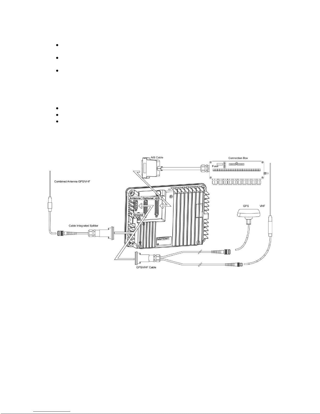
3.2 Installation Overview..................................................................................................................................................5
3.3 General Interface Description.....................................................................................................................................7
3.4 Interface NMEA Description:......................................................................................................................................8
3.4.1 Sensor - Interface CH1, CH2, CH3...................................................................................................................8
3.4.2 ECDIS –Presentation Interface CH 4...............................................................................................................8
3.4.3 Pilot Port CH 5 .................................................................................................................................................9
3.4.4 Long Range CH 8 ............................................................................................................................................9
3.4.5 DGPS –DGNSS Channel 9...........................................................................................................................10
3.4.6 Alarm Circuit –BIIT Channel 10.....................................................................................................................10
3.4.7 Proprietary Sentences....................................................................................................................................10
3.5 Sensor Interface Definitions.....................................................................................................................................11
3.5.1 Talker drive circuits ........................................................................................................................................11
3.5.2 Listener Receiver Circuits...............................................................................................................................11
3.5.3 Electrical isolation ..........................................................................................................................................11
3.5.4 Maximum voltage on the bus..........................................................................................................................11
3.5.5 Data transmission ..........................................................................................................................................11
3.6 Sensor notes............................................................................................................................................................12
3.7 Sensor Hardware Installation:..................................................................................................................................13
3.7.1 Installation of an RS422 serial interface:.........................................................................................................13
3.8 Sensor Software Configuration ................................................................................................................................14
3.8.1 Introduction....................................................................................................................................................14
3.8.2 Set up Sensor Speed, Checksum (CRC) and NMEA Talker and Sentence ID................................................14
3.8.3 Real-Time Analysis of NMEA Data Streams...................................................................................................17
3.8.4 Sensor Monitoring for Problem Analysis.........................................................................................................19
3.8.5 Priority Handling of Sensor Sentence.............................................................................................................20
3.8.6 Supported NMEA-0183 Sentences.................................................................................................................20
3.8.7 Calculated Values ..........................................................................................................................................24
3.8.8 Versions of NMEA Sentences ........................................................................................................................24
3.9 Pin-Description AIS-Cable / Socket 50-Pins:............................................................................................................25
3.10 Pin-Description AIS-Connector:...........................................................................................................................26
3.11 Pin-Description Communication-Cable / Socket 50-Pins .....................................................................................27
3.12 Communication Cable RS232 (Sub-D 50 Socket) ...............................................................................................28
3.13 Installation of VHF / GPS Antennas.....................................................................................................................29
3.13.1 VHF Antenna Installation................................................................................................................................29
3.13.2 GNSS Antenna installation.............................................................................................................................30
3.14 Power Supply......................................................................................................................................................33
4STARTING THE NAUTICAST™........................................................................................................................................34
4.1 Initial Set Up of the NAUTICAST™for operation .....................................................................................................34
4.2 Entering the MMSI / IMO / DAC / ESN Numbers......................................................................................................35
4.3 Entering Ship Settings .............................................................................................................................................37
4.4 Entering Voyage Related Data.................................................................................................................................39
4.5 Entering Inland AIS Configuration............................................................................................................................43
4.6 Service and User Passwords...................................................................................................................................45
5TROUBLESHOOTING.......................................................................................................................................................48
5.1 Reading and understanding Alarms: ........................................................................................................................48
5.2 Alarm Codes............................................................................................................................................................49
5.3 Text Messages .......................................................................................................................................................50
5.4 Restarting the NAUTICAST™..................................................................................................................................50
6ACCESSORIES.................................................................................................................................................................51
7TECHNICAL INFORMATION ............................................................................................................................................52
7.1 ERI Ship Types........................................................................................................................................................53
8CONTACT AND SUPPORT INFORMATION.....................................................................................................................54
9APPENDIX........................................................................................................................................................................55
9.1 Samples for battery calculation................................................................................................................................55
9.1.1 Typical Installation..........................................................................................................................................55
9.1.2 RM GMDSS Compact-Console Area A3 with 250 W MF/HF...........................................................................56
9.1.3 RM GMDSS Compact-Console Area A3 with 400 W MF/HF...........................................................................56
9.2 Drawings and Approvals..........................................................................................................................................57