HornBlasters 127H User manual

CONDUCTOR'S SPECIAL
INSTALLATION MANUAL
127H / 228H
WARNING: To ensure the longevity of your
system, reading and following these instructions
are recommended. Make sure to change filters
and to drain the moisture from your tank on a
regular basis.
BEFORE YOUR PROCEED! THE AIR SOURCE
IN THIS KIT IS NOT MEANT TO BE MOUNTED
OUTSIDE IN THE ELEMENTS! IT IS NOT
WEATHER PROOF AND WILL NOT BE
COVERED UNDER WARRANTY IF MOUNTED
OUTSIDE OR EXPOSED TO THE
ELEMENTS! MUST BE MOUNTED UPRIGHT.
Page 1

HORNBLASTERS CONDUCTORS SPECIAL 127H/228H KIT CONTENTS
Identifying Fittings
•Air Source Kit (127 / 228H)
• HornBlasters Shocker XL Horns
• 17’ 1/2” Airline
• 10’ 5/16” Airline
• Air Source Mounting Hardware
•1/2" Electric Solenoid Valve
•Ear Plugs
•Air line Cutter
•HornBlasters Universal Wiring Kit
The diameter of the thread (X) will indicate what size thread a
fitting has. If you're not sure which fittings are 1/2", 3/8", or 1/4",
measure the thread on each fitting and match it up with the values
below.
1/2" NPT 3/8" NPT 1/4" NPT 1/8" NPT
0.84" 0.675" 0.54" 0.405"
1x
1/2" PTC
Fitting
4x
Shocker Horn
Elbow
1x
1/2" Solenoid Valve
1x
Banjo / 4-Way Splitter
1x
127 / 228 Air
Source
1x
Shocker XL
Horns
17 Feet
1/2" Air line
10 Feet
5/16" Air line
Page 2

www.hornblasters.com [email protected]
Safety Tips and Important Information
IMPORTANT SAFETY INSTRUCTIONS
WARNING: To prevent injury:
Caution: To prevent the risk of electric shock or electrocution:
•Do not disassemble any electrical components of this horn kit (air compressor, air valve, pressure switch).
•Do not attempt repairs or modifications of any component. Please refer to qualified service agencies for all
service and repairs.
•Do not operate any component where it can fall or be submerged into water or any kind of liquid.
•Do not reach for any component that has fallen or been submerged into water or any kind of liquid.
•Use the included components with 12 volt DC systems only.
•Do not leave the air system unattended during use.
•Never allow children to operate the compressor or air horn. Use close supervision when operating this
equipment near children or animals.
•The air compressor will become very HOT during and immediately after operation. Do not touch any part of
the compressor with your bare hands during or immediately after use.
•Do not use this product near open flames or explosive materials or where aerosol products are being used.
•Do not operate this product where oxygen is being administered.
•Do not pump anything other than atmospheric air.
•Never use this product while sleepy or drowsy.
•Do not use any tools or attachments with the supplied air source unit without first determining maximum air
pressure for that tool or attachment.
•Never point any air nozzle or air sprayer toward another person or any part of your body.
•The included compressor is equipped with an automatic reset thermal protector and can automatically
restart after the thermal protector resets. Always cut off power source when thermal protector becomes
activated.
•Use only in well ventilated areas.
•Do not sound the air horn(s) in close proximity to another person’s or your own ear(s).
•Do not fill the included air tank above 150 PSI. Doing so may result in death or serious injury.
•Disconnect the battery negative cable before doing anything. Failure to disconnect this terminal can lead to
damaged electrical components.
•Use eye protection when operating drills or other power tools during the install.
•Ensure the parking brake is engaged before you get underneath the vehicle.
•Do not wire the system without the fuse holder.
•Do not allow the compressor to run when the vehicle is off.
Page 3

Recommended Tools + Addons
Recommended Tools
Optional Install Items (Not required but will make your install easier)
Compatible Add-on Kits (available @ www.HornBlasters.com)
•3/8” Long Socket (Horn Front Mount)
•1/2” Long Socket (Horn Rear Mount)
•1/2” Wrench
•7/8” Wrench (4-Way Splitter on Valve)
•10mm Wrench or Socket (Air Source Mounting)
•12mm Wrench
•Drill (3/16" & 7/16" bits)
•Wire Cutter / Stripper / Crimper
Part #
Tire Inflation Kit
Description
Adds a quick disconnect to your system which allows
you to use air tools with our kit. AA-TIK-H
Electric Drain Valve Kit Replaces the drain cock with a solenoid valve; allows
for remote draining of the system AM-D04K
Digital Air Gauge 2' Digital Air Pressure Gauge allows you to monitor the
tank pressure in the cab GA-220H
Six Horn Upgrade Adds two more bells to the system for more
volume! HU-S6-1
Shocker Horn Bracket Mounting plate for the set of four horns only HB-SB-1
Name
•Add-a-circuit - Great for tapping into a key-power source from your fuse-box.
•Self-Tapping Screw - These can be used for ground points on the pressure switch, compressor, and valve.
•Slotted Angle Iron - Can be used to mount the horns without making a plate.
•Cable Ties - Used to keep your air line looking clean and organized.
•Heat Shrink Tubing - Can be used over the terminal connectors to better seal them up against the
elements.
•1" Adjustable Wrench - Makes it easier to get the brass fittings into the tank. You can use one wrench for
all the fittings on the system.
•Thread Sealant - Can be used instead of Teflon to seal fittings.
Page 4

Preparing For the Install
Recommended Install Locations for Your Car (Compressor)
Recommended Install Locations for the Horns
•The trunk of your car/sedan/suv is a great spot for this air source kit. The trunk keeps the compressor
out of the weather and is one of the best install locations for the compressor/tank combo.
•The engine bay can also be used as an install location for the air source. If you have enough room to
mount the air source without getting too close to the engine, this will work just fine. Do not mount the
compressor to close to engine. If the compressor gets too hot, it will not run.
•If you decide to mount the compressor outside the car make sure it won't get submerged if you go
through a large puddle! It can get wet but you cannot submerge the system.
Check out the install photos below, these are two examples of installs in the rear storage area of a car with a sub.
•These horns will sound their best when facing down towards the ground, or towards the front of the vehicle
(these can face forward!) We typically see these mounted behind the front bumper, ahead of the radiator on
most vehicles. (see picture below, to the right)
oIf you opt to install the horns in the front grille, make sure that the opening at the end of each bell is not
blocked or covered. Make sure to leave some room for airflow to your radiator!
Horns installed
underneath a car
Horns installed
in the front
grille of a car
Page 5

Preparing For the Install (continued)
Recommended Install Locations for Trucks (Compressor)
Recommended Install Locations (Horns)
•The toolbox is a great location for the compressor. Do not use the toolbox as a grounding point.
•Mounting the compressor/tank in the bed (if covered) is a great option.! Some full size trucks will have
room behind the seats to mount the air system.
•The engine bay is a good spot for the compressor as long as you keep it away from the exhaust manifold and
engine block. The compressor must remain upright and attached to the tank as well.
•You can mount these horns in the front bumper similar to a car or underneath the bed.
•If you face the horns forward when mounted underneath they may pickup some dirt/dust from the road. This
is normal and will not damage the horn. Make sure to honk the horns regularly to keep any buildup or dust/
dirt out of the horn assembly.
Page 6

Good Cut Bad Cut Ensure each air line is fully seated over the
compression fitting before tightening the nut
down over it. If the line is not fully seated over
the barb, it can slip off the fitting even with the
nut in place. Hold the line in place and use a
wrench to tighten the compression ferrule down.
Use a flathead screwdriver to pry
the filter housing apart. You can
insert the flat end of the
screwdriver into seam, where the
arrow is
Remove the old filter element
from the housing. Insert the new
element into the center so that
the white portion of the filter lines
up with the plastic tabs. Replace
the cover back over the housing,
lining the tabs up on the sides of
the cover.
The compressor filter must be
changed out every 2-3 months,
otherwise the compressor will
start to pull in dirt/dust and wear
prematurely.
Make sure the 5/16" lines are equal length!
Plumbing Diagram
Plumbing the air line to the tank
Page 7

6511 N 54th St
Tampa, FL 33610
+1 (813) 783-8058
Fax: +1 (813) 783-2407
www.hornblasters.com [email protected]
2-GALLON CONDCUTORS SPECIAL 127H/228H WIRING DIAGRAM
30A fuse
(-)
Cut fuse in half at center point
Page 8

+1 (813) 783-8058
Fax: +1 (813) 783-2407
www.hornblasters.com [email protected]
Wiring Instructions
Wiring the Relay
Pin 30: This pin will connect to the battery positive terminal. You MUST use the supplied 10-gauge RED
wire for this connection. Use the supplied tan or green terminal to connect the red wire to this pin. Cut the
fuse holder wire in half at the center point. Connect one end to the battery positive terminal. Connect the
other end to a lead of 10 ga. red power wire that runs back to the relay.
Pin 86: This pin will connect to a key-power source. You are looking to connect this pin to any circuit that is
ONLY ON WHEN THE VEHICLE IS ON. This will prevent your kit from running when the vehicle is off.
Common key-power sources include the cigarette lighter fuse, sunroof, radio, trailer running lights, daytime
running lights, etc. You can use any circuit that is rated for 5A or less. The relay only needs a fraction of an
amp to operate.
Pin 85: Route a lead from this pin to the frame of the vehicle as a ground point. You may use the supplied
Blue or Grey wire for this connection. You can use a wire brush on the frame or bed coating to ensure a
good connection to metal is made.
Pin 87: Take the red lead coming off the compressor/tank combo and connect it directly to this pin.
Your relay is now wired and ready for use. You can use a small lead of wire to connect pins 30 & 86
together to test the relay. If you have this wired correctly, the relay should make a light 'click' sound when
the two pins are connected. This means the relay is turning on and off properly. When you start the
vehicle, it will send power to pin 86 and turn the relay on, which will allow the compressor to run.
Key-Power-Source (Normal Method)
If you're having trouble locating a fuse that is only hot when the vehicle is on, you can go online to https://
fuse-box.info/. You can use a test light to check whether or not the fuses are hot with the key in the off
position. Route the black probe/clip to the battery negative terminal (-) and use the red probe on the metal
contacts of the fuse(s) you want to check. If the light comes on, your fuse is hot. If the light does not turn
on, start the vehicle and check for current. The light should illuminate now that the vehicle is running.
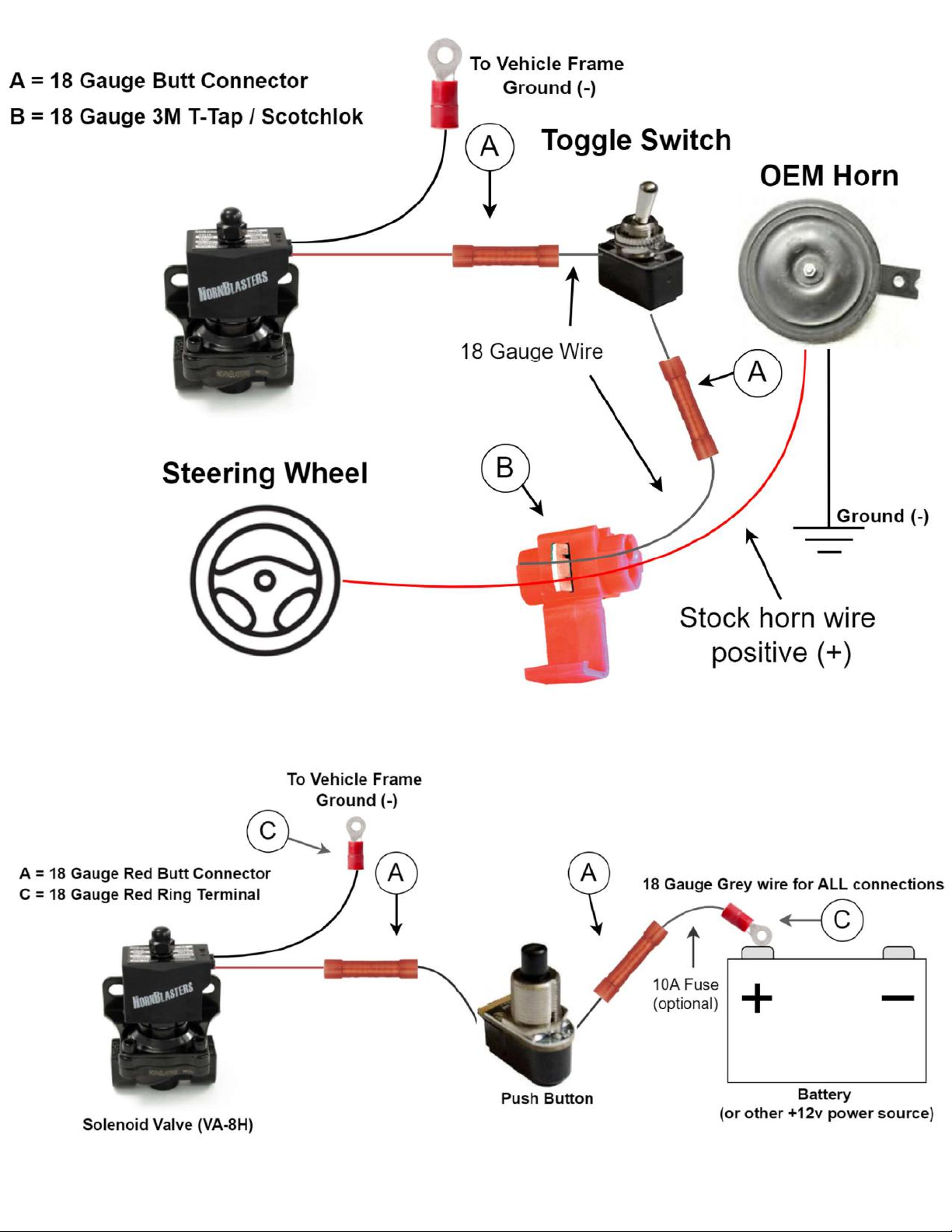
Using A Toggle Switch Instead of a Key Power Source
If you can't find a good key power source, you can use a toggle switch instead to manually stop the
compressor from running. To do this, locate the supplied toggle switch that came with your horn kit. Wire
one lead of the toggle switch to +12v power and take the opposite lead of the toggle switch to pin 86 on the
relay. When you flip the switch on, the relay will switch on and allow the compressor run. Wiring your kit
this way means that you MUST turn the switch off with the vehicle, otherwise the compressor could run
overnight and drain your battery.
6511 54th St
Tampa, FL 33610
Page 9

Connecting the Train Horns to a Push Button
Connecting the Train Horns to the Steering Wheel
Page 10

•
•
•
www.hornblasters.com [email protected]
Maintenance / Tips (Do not throw this away!)
Drain Cock
Closed Position
Drain Cock
Open Position
!
Once every ...
•
2 Weeks
o
Drain the air tank of moisture! Do not let the water build-up in the tank longer than 2 weeks. The
water can find it's way into your horns and cause them to sound squeaky or not at all. The water can
also find it's way into your pressure switch and cause it to fail.
•
Month
o
Check the air filter element for the compressor. If the element is showing signs of dust/dirt build-up,
replace it with a new one.
•
2 Months
o
Check your air lines and make sure they're not rubbing against anything. Inspect the horns for
damage.
o
Check your wiring for corrosion (especially in the winter time) If the terminal connectors become
oxidized or corroded, the kit could stop working at random in the future.
•
3 Months
o
Replace the filter if you haven't already. Inspect the filter if it was recently replaced.
o
Check the tank for leaks. After being installed on your vehicle for some time, the vibration from daily
use can cause a small leak to occur at the fittings or air line connections. Spray down with Windex
or soapy water to find the leak point.
•
Year
o
Check your ground connections. If the connection to the frame isn't that good or comes loose, the
compressor or solenoid valve will stop working properly.
►
Use a wire brush to clean these up if needed.
o
Inspect your mounting hardware for the compressor/tank/horns. Ensure all components are still
secured nice and tight.
Page 11

•
•
•
www.hornblasters.com [email protected]
Troubleshooting
Compressor
•The compressor doesn't turn on.
oTry connecting the compressor to a 12v battery directly.
Take the red wire to the positive terminal and the black wire to the negative terminal.
Give us a call if the compressor doesn't run. If it does, go to the next step.
oDouble check the wiring for the relay. Test the relay if needed
Make sure that pin 86 is connected to a good key-power source and ensure than pin 85 is
grounded properly. You can test the relay wiring by connecting a small wire from pin 30 and
jumping it over to 86. If the compressor runs when you do this, you need to check your key-
power source. It is not giving power to the relay.
oMake sure the fuse isn't blown
If the fuse is blown, this could be due to a short in your wiring. Before you put a new one in,
check and ensure your wire is not frayed or exposed anywhere.
•The compressor doesn't fill the tank
oMake sure the drain cock isn't open
Refer to page 11. If the drain is open, the tank is not sealed and cannot pressurize.
oMake sure the valve isn't open or backward
If the valve is open, the air from the compressor is escaping through it constantly. If the valve
is backward, air will escape through it constantly.
oCheck the compressor's air inlet (only applies if you have a 228H)
If the plug from the inlet was not removed, the compressor cannot suck in air. Remove the
filter and remove the plug.
Make sure to check that you removed the plug from the end of the compressor's leader hose.
If the plug is still present, the compressor will not be able to push air out of the hose.
•The tank loses pressure after a few hours
oSpray each fitting and air line with soapy water or Windex®.
The liquid will bubble up anywhere a leak is present. Typically, fittings need to be tightened
further or more Teflon tape needs to be applied to the thread. If you have a leak from the air
line connections, re-cut the lines flush and re-seat them into the PTC fittings.
Page 12

•
•
•
www.hornblasters.com [email protected]
Troubleshooting
Horns
•The horns won't honk
oCheck the air tank for air pressure. If your air gauge reads 0 PSI, refer to the steps on page 12 to
remedy the lack of air in the tank.
oCheck the wiring for the horn solenoid valve. If the valve has a loose ground connection, it will not work
properly. Make sure the valve is connected to your activation switch.
oCheck the power source for the horn activation. Use a test light or voltmeter to check for +12v on the
lead coming from your stock horn wire or power source. Make sure power is coming into and out of the
activation switch/button.
•The horns don't sound right
oIf your horns start to squeak or sound high-pitched, drain the tank. Moisture buildup in the tank is finding
it's way from the tank into your horns. This causes them to squeak.
Drain the tank of moisture. Disconnect the lines from each horn bell but leave them connected to
the 4-way. Let the tank build pressure and then press the horn button. The rush of air through
the lines will remove excess moisture.
oCheck and ensure the end of each bell isn't obstructed or blocked. The horns will sound off at a different
pitch when the opening of the bell is blocked.
•The horn honks on it's own as soon as it is wired up
oThis is a tricky problem to fix and can be confusing to most. On some vehicles, the stock horn receives
a constant feed of power from the battery. When the wheel is pressed, a switch inside the steering
wheel creates the ground for the horn circuit and the horn honks. When you wire your OEM horn wire to
our valve, the valve ground completes the circuit and causes the constant honk.
We can fix this problem by following these steps:
1. Disconnect the valve ground from the frame.
2. Splice from the OEM horn NEGATIVE lead and route this to the toggle switch.
3. Connect the opposite lead of the toggle to the black wire on the valve.
This makes it so that the valve is actuated from the negative side of the OEM wiring. If you have
trouble with this, give our team a call @ (877)-209-8179.
oMake sure the valve isn't connected to a constant power source. If the valve is receiving power
constantly, it will stay open.
•It sounds like the horns are going off at different times
oCheck the length's of each air line from the 4-way splitter to each bell. If these lines are not equal length,
the horns will sound off at different times. This is not ideal.
Check and ensure each air line is secure in the elbow fittings. If one line is loose or
disconnected, the other horns will sound muffled due to the loss of air pressure.
Can't find your issue listed above? Give our team a call @
(877)-209-8179 or shoot us an email to [email protected]
Page 13

Page 14
Other manuals for 127H
1
This manual suits for next models
1
Table of contents
Other HornBlasters Automobile Accessories manuals

HornBlasters
HornBlasters 127VX User manual

HornBlasters
HornBlasters ROCKER User manual

HornBlasters
HornBlasters Psychoblaster User manual

HornBlasters
HornBlasters 127H User manual

HornBlasters
HornBlasters AIRHORN Bullet 2MC User manual

HornBlasters
HornBlasters AIRHORN Bullet 2MC User manual

HornBlasters
HornBlasters NATHAN AIRCHIME User manual