Starrett St-1101 User manual

REV. A JAN/10
Instruction manual for the installation and
maintenance of band saw machine model:
St-1101
Serial Number:
Date:
REV A JAN/10 1
1 . GENERAL PROVISIONS AND REFERENCES :
1.1 General:
This Instructions Manual consists of 9 Sections containing relevant and
important information to be observed. Such information will be "named” in
accordance with the symbols appearing below in boldface.
WARNING:
Operation, technical and other
procedures likely to cause
physical damages to operator
and/or to equipment;
OBSERVATION:
Operation, technical and other
procedures that must be
emphasized and observed;
ELECTRICAL
INSTALLATION:
Important Electrical Installation
procedures.
For any doubts a user could have on the Starrett machine, the Customer
Service Center, through its Technical Support Service, will be at your disposal to
promptly assist you in your cutting needs.
This Manual presents a serial number that coincides with the machine serial
number. Should you experience any problem within the machine warranty period
please mention this number (See Warranty terms in Section 8).
2 REV A JAN/10
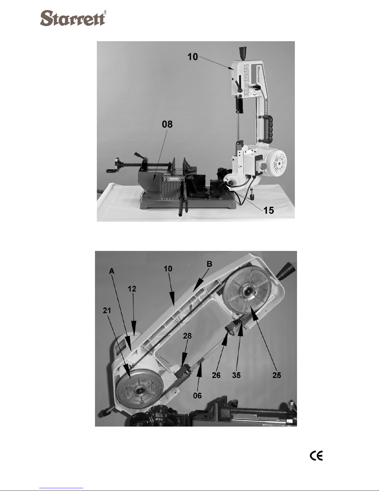
1.2 Figure and Part References:
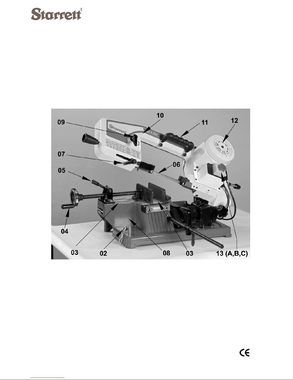
Figure 01A

REV A JAN/10 3
Figure 01B
4 REV A JAN/10
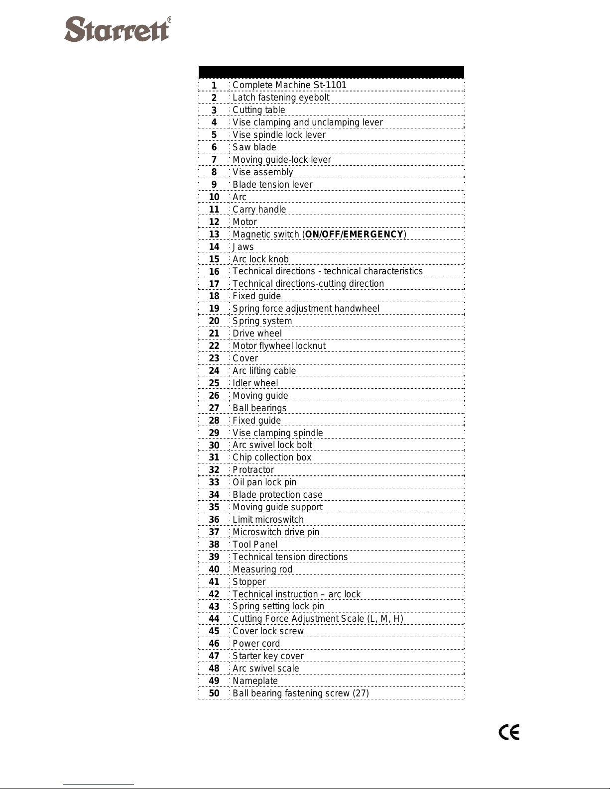
POS. DESCRIPTION
1 Complete Machine St-1101
2 Latch fastening eyebolt
3 Cutting table
4 Vise clamping and unclamping lever
5 Vise spindle lock lever
6 Saw blade
7 Moving guide-lock lever
8 Vise assembly
9 Blade tension lever
10 Arc
11 Carry handle
12 Motor
13 Magnetic switch (ON/OFF/EMERGENCY)
14 Jaws
15 Arc lock knob
16 Technical directions - technical characteristics
17 Technical directions-cutting direction
18 Fixed guide
19 Spring force adjustment handwheel
20 Spring system
21 Drive wheel
22 Motor flywheel locknut
23 Cover
24 Arc lifting cable
25 Idler wheel
26 Moving guide
27 Ball bearings
28 Fixed guide
29 Vise clamping spindle
30 Arc swivel lock bolt
31 Chip collection box
32 Protractor
33 Oil pan lock pin
34 Blade protection case
35 Moving guide support
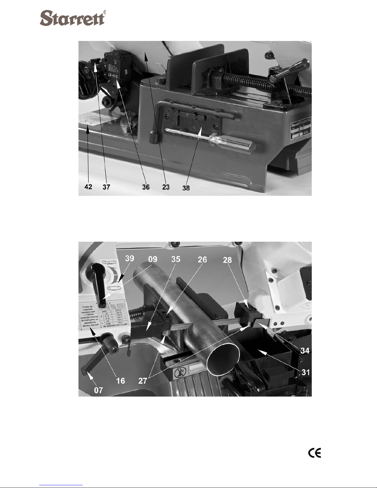
36 Limit microswitch
37 Microswitch drive pin
38 Tool Panel
39 Technical tension directions
40 Measuring rod
41 Stopper
42 Technical instruction – arc lock
43 Spring setting lock pin
44 Cutting Force Adjustment Scale (L, M, H)
45 Cover lock screw
46 Power cord
47 Starter key cover
48 Arc swivel scale
49 Nameplate
50 Ball bearing fastening screw (27)

REV A JAN/10 5
2 . APPLICATION, GENERAL DESCRIPTION AND
TECHNICAL CHARACTERISTICS:
2.1 Application (adequate use):
THE STARRETT–St-1101 HORIZONTAL BAND SAW was developed
to meet the quality, safety, modernity and technology criteria, in response to user
needs, in conformity with CE standards.
This machine is intended for PROFESSIONAL and/or HOBBY, PORTABLE
use, recommended for cutting structural shapes, thin-wall tubes, made of low-
carbon ferrous or non-ferrous materials (bronze and aluminum alloys, among
others). The physical characteristics of such materials, such as hardness, tenacity
and density, should pose no safety problems for users during cutting operations.
This equipment IS NOT recommended for cutting materials whose production
volumes are high and continuous, i e., involving several operating hours each day.
In such cases, Starrett recommends one of its other machine models more
specifically developed and designed for large volume cutting operations.
If used in INDUSTRY, the technical characteristics and machine cutting
capability limits shall be complied with (item 2.2 –Technical Characteristics), or else
stand liable for LOSING THE WARRANTY granted by Starrett. If in doubts,
Starrett will be at your disposal for any clarifications.

6 REV A JAN/10
2.2 General Description:
2.2.1 Arc Assembly
The machine comprises of a sturdy Arc (10) provided with 2 Wheels: one
Idler Wheel (25) and one Drive Wheel (21), the latter coupled to a Speed Reducing
Gear. The Idler Wheel (25) is mounted on the shaft of a Saw Blade Tension Device
(09).
A welded Saw Blade (06) is mounted around the two wheels and
conveniently tensioned by the Tensioning Device (09), to keep the blade properly
tensioned by the Wheels (21)(25). The Arc (10), in turn, is mounted on the Vise
Assembly (08) through a shaft that allows the arc to pivot on the saw plane, thus
creating a cutting plane (figure 01A). The Blade (06) and Wheels (21)(25) are duly
protected at the back of Arc (10) by a Protective Cover (23) (figure 02).
In order to move the Arc (10) upwards (figure 04), it should be first
unlocked by the Arc Lock Knob (15).
The machine is so designed as to cause the Arc (10) to swivel around a fixed
point on the Vise Assembly (08), i.e., along a plane at right angles to the Cutting
Table (03), to allow for angular cuts to be made on the material to be cut (figure 10).
The cutting pressure of the Saw Blade (06) on the material is set through a
Spring System (20) (figure 07), which is part of the Arc assembly (10). Such spring
system allows for 3 settings to be available: HIGH (H), MEDIUM (M) and LOW (L),
duly marked on the Wheel (19), as can be seen in figure 08.
The Saw Blade cutting segment (06) is supported by two Guides (26)(28).
Such Guides are provided with Ball Bearings (27), which allow the blade to be
twisted by 45º relative to the rotation plane of Wheels (21) (25), to form the cutting
plane. Such Ball Bearings (27) are intended to align and prevent the Saw Blade (06)
from laterally deflecting around the axis of its track movement. The Moving Guide

REV A JAN/10 7
Support (35), close to the driven Wheel (25), can be manually adjusted by loosening
Knob (07), to set its distance relative to the material to be cut (figure 03).
2.2.2 Vise Assembly
The Vise Assembly (08) (figure 01A) is intended to securely clamp the
material to be cut to the Cutting Table (03) and forms the base of the machine,
made of injected aluminum alloy. Such assembly is comprised of:
- Cutting Table (03);
- Jaws (14);
- Tightening Spindle (29);
- Lever (04).
- Coupling Lock Lever (05).
2.2.3 Electrical System
An Electrical Panel (13A, 13B e 13C) is coupled to the Arc Assembly (10), as
shown in figure 01 A. This electrical system comprises a magnetic ON-OFF switch
that drives the machine (13A, 13B), and a mushroom-type emergency button (13C).
The machine operates on SINGLE PHASE 220V, at 50 or 60 Hz frequencies.
It allows for one single cutting speed, which changes according to the mains
frequency: 45 m/min under 50 Hz or 54m/min under 60 Hz.
8 REV A JAN/10
Figure 02
Figure 03

REV A JAN/10 9
2.2.4 Machine operation:
With the machine duly adjusted, electrically connected, with the material to
be cut properly positioned and locked on the Cutting Table (03) and with the Arc
(10) in its raised position, open the yellow cover containing the Switch Assembly (13
A, B, C) (figures 01, 09), and actuate the green Button ON (13A). Manually position
the Saw Blade (06) over the material to be cut, by means of the Lifting Cable (24).
This operation will start the Saw Blade (06) cutting motion on the material. At the
end of the cutting operation, the Drive Pin (37) will touch the Limit Microswitch (36)
(figure 07), automatically switching off the Electric Motor (12).
For being a portable equipment for professional and/or hobby use, the
STARRETT–St-1101 Horizontal Band Saw Machine does not embody a cooling
system. Therefore, in order to guarantee its safe and quality operation, the operator
must observe the cutting conditions. As an OPTIONAL item, the STARRETT St-
1101 can be provided with a Portable Tubular Table called BPM (see Section 2.4).
NOTE:
The Saw Blade cutting segment (06) (between Guides (26)(28)),
obviously has no protection, being the responsibility of the
machine operator to act carefully and taking the necessary
precautions.
All necessary details of the systems comprising this machine will be
described in their relevant Sections.
10 REV A JAN/10
Figure 04
Figure 05

REV A JAN/10 11
2.3 Technical Characteristics:
Net Weight (kg): 23
Dimensions(m): 0.73 x 0.38 x 0.46 (height)
Main Motor (HP / KW) 0.5 / 0.37
Saw Speed (m/min): 45 (under 50 Hz)
54 (under 60 Hz)
Saw Blade Dimensions (mm): 1470 ( ±2 ) x 13 x 0.50 or
1470 ( ± 2 ) x 13 x 0.65 (*)
Single phase voltage (V): 220
Motor operating frequency (Hz): 50 or 60
Permissible Cutting Sizes (mm):
(*) the St-1101 comes equipped and adjusted with a 0.50-thick band saw blade. If willing to fit it with
a 0.65mm-thick blade, please refer to the instructions in item 4.6.
The St-1101 IS NOT provided with a cooling system.
This is a DRY cut-off machine.
2.4 Optional:
BPM – Portable Tubular Table
1 - Structural tubes and shapes 2 – Solid
W x H W x H

MANUALDEINSTRUÇÃOLINHACDS6240A–REV.NOVA‐OUT/09
VITOR&BUONOLTDA
RuaCruzeiro,48–BarraFunda
CEP01137‐000SÃOPAULO/SP–BRASIL
Tel(11)3376.777fax(11)3376.7776
www.vitorbuono.com.br
MANUALDEINSTRUÇÃO
TORNOMECÂNICOUNIVERSAL
MODELOS:
CDS6240A,CDS6240B,CDS6240C
CDS6250B,CDS6250C
CDS6256B,CDS6256C
CDS6266B,CDS6266C
CDS6276B,CDS6276C

7. MANUSEIO E INSTALAÇÃO:
7.1 - MANUSEIO E ARMAZENAGEM:
A máquina é protegida contra oxidação e a prova de choques durante o seu
transporte, por uma embalagem adequada para tal. No período de transporte e
armazenagem o equipamento suporte temperaturas entre -25 a 55ºC, e até
70ºC por menos de 24 horas.
Este equipamento durante o seu transporte e sua armazenagem NÃO deve ser
exposta a chuva e deve EVITAR qualquer tipo de dano devido a estas
operações.
O material da embalagem não polui o ambiente.
7.1.1- Elevação da máquina:
Um cabo de aço deve ser usado durante a elevação da máquina conforme
usado na caixa. Não deixe a máquina sofrer choques ou vibrar durante a
elevação e descarregamento.
Em nenhuma circunstância, não deixar a máquina inclinada.
Enquanto estiver desembalando, VERIFICAR a aparência primeiramente,
depois VERIFICAR os acessórios, ferramentas e documentos técnicos se todos
estão conforme a lista do pedido.
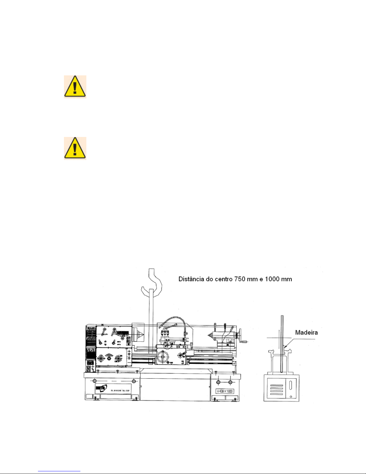
Para máquinas com distâncias entre centros de 750 mm a 1000 mm, a posição
de içamento com correia própria para elevação de carga (de trama angular)
deverá ser feita perto da Placa de Fixação, conforme figura 01 abaixo.
Para máquinas com 1500 mm, 2000 mm ou 3000 mm de distância entre
centros, a posição do içamento deverá feita em 2 pontos sendo um mais
próximo da Placa de Fixação e o outro ponto próximo do Contra-Ponto,
conforme figura 01 abaixo. Quando elevar, coloque blocos de madeira entre a
língua e as guias do Barramento para protegê-las de danos. Em nenhuma
circunstância, deixe a máquina inclinada.
O diâmetro do cabo de aço não deve ser menor que 22 mm e tem que ser firme
o suficiente para elevação. A capacidade de elevação é maior que 4 ton + o
peso da máquina (para o peso da máquina, veja a tabela 3,3 – Dimensão total
da máquina e peso líquido).
Ao elevar a máquina mantenha a área limpa e se for necessário, reajustar e
reposicionar o carro do torno para alcançar o melhor equilíbrio antes de elevá-
la.
CUIDADOS!
A capacidade de elevação deve ser maior que 4ton + peso da máquina; o
diâmetro do cabo deve ser maior que 22 mm.
NOTAS:
•Mantenha o equilíbrio da máquina durante a elevação quando a
mesma estiver sendo erguida do chão;
•O ângulo do cabo de elevação é menor que 60º;
•Quando a elevação da máquina é feita por duas pessoas ou mais,
sinais devem ser usados entre os operários;
•Verifique a tensão do cabo de içamento antes de elevar;
•Carregamento seguro dos equipamentos deve ser conhecido
claramente; o coeficiente de segurança é 6:1.
Figura 01A – Elevação da máquina
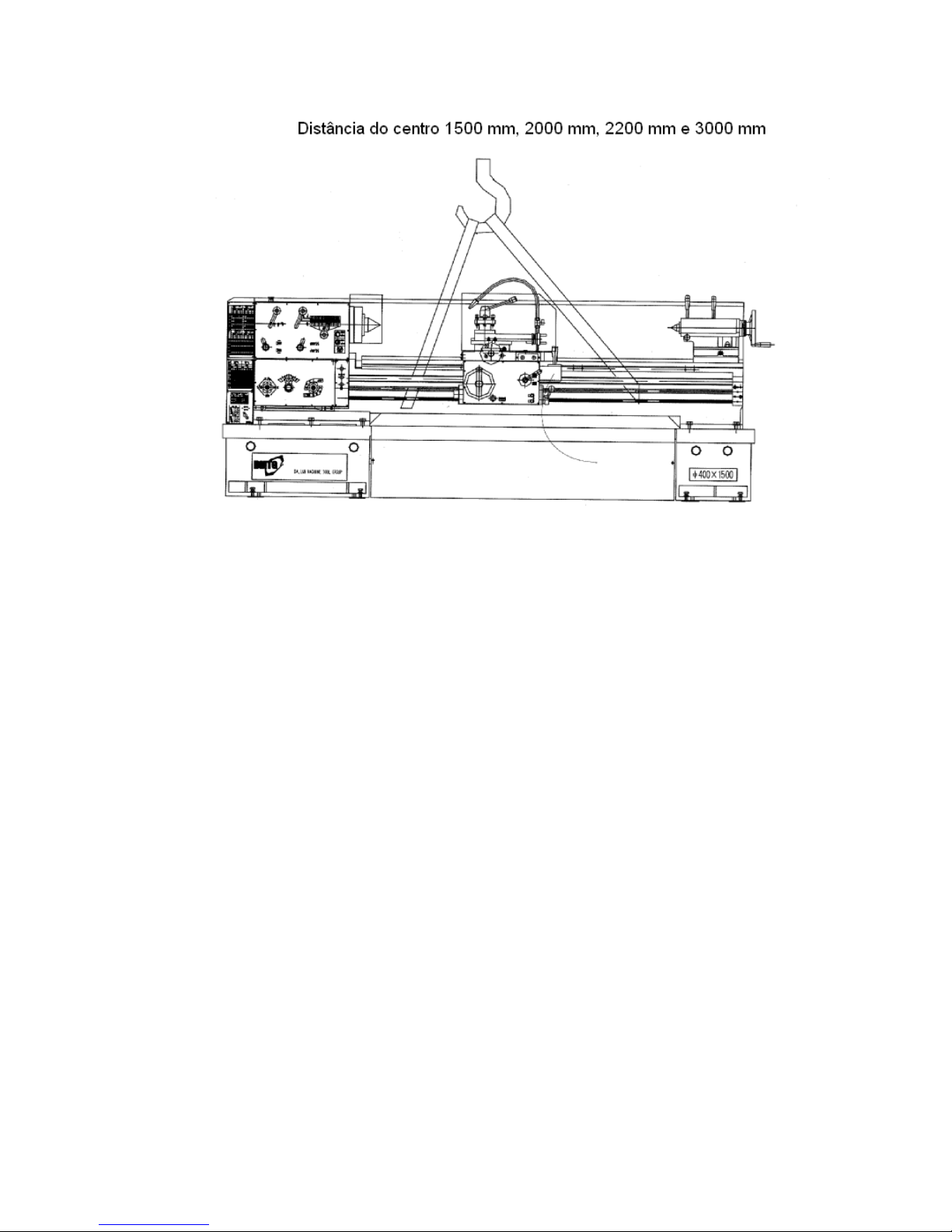
Figura 01B – Elevação da máquina
7.2 INSTALAÇÃO:
7.2.1. Preparação:
Preste atenção aos itens seguintes além da instalação adjacente que devem
ser feitos conforme mostrados no Manual de Instruções:
•INSTALAR a máquina sobre um piso nivelado e desempenado, cuja
fundação seja sólida, e deixando área suficiente para operação e
serviço. O torno pode ser usado somente apoiado, mas para a
performace máxima deve estar fixado na fundação;
•A máquina deve estar instalada em uma área que tenha iluminação
adequada, sem contaminação, sem acessórios diversos e boa condição
de ventilação;
•INSTALAR a máquina em uma área com dispositivo de contra
relâmpago;
•Se a máquina for instalada em uma fundação não solidificada, procurar
encontrar soluções e medidas similares, a fim de melhorar a força de
apoio da máquina sobre o do solo para evitar afundamento e inclinação;
•Se a máquina está localizada em um lugar perto de uma fonte de
vibração, faça uma vala ao redor da máquina ou outro dispositivo anti-
vibração para evitar esta influência;
•A máquina não pode ser montada em local, onde há um potencial de
perigo de explosão.
7.2.2 - Conexão da energia elétrica:
Torno sem quadro elétrico: a entrada do cabo de alimentação está na base da
máquina.
Torno com quadro elétrico: o cabo de alimentação está no quadro elétrico do
gabinete.
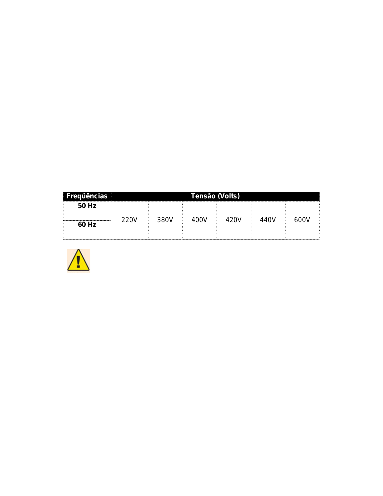
Principais opções de tensões elétricas:
De acordo com o pedido ou contrato de compra, o cliente terá as seguintes
opções de tensão (voltagem) e de freqüência da rede elétrica.
Tensão x Freqüência:
Freqüências Tensão (Volts)
50 Hz
220V
380V 400V 420V 440V 600V
60 Hz
ATENÇÃO!
Limites da tensão:
A tensão elétrica poderá variar na faixa de ± 10% em relação a nominal.
Para maiores detalhes veja a seção de Sistema elétrico do Manual deste
Manual de Instruções.
7.2.3 – Instalação:
A forma de instalação poderá afetar em muito o desempenho da máquina. Para
alcançar as precisões desejadas é necessário que a mesma esteja instalada
corretamente, conforme instruções deste manual. Além disso, o não
cumprimento correto da instalação poderá diminuir a vida útil do equipamento.
A maioria das más funções é causada por instalações incorretas.
Leia detalhada e cuidadosamente os passos de instalação, e instale o torno
conforme mostrado. Caso contrário, com já mencionado, poderá afetar a
precisão e a vida útil da máquina.

7.2.4 – Fundação:
Prepare a fundação de acordo com seus arredores e plano de fundação (figura
2) e coloque o torno em uma fundação plana e desempenada. O espaço para
manutenção deve ser considerado.
Figura 02 – Fundação
Dim
BC a b c d e
750 1130 2350 ---- ---- ----
1000 1380 2600 ---- ---- ----
1500 1880 3100 ---- ---- ----
2000
2200 1380 3600 1070 126 350
3000 3380 4600 1600 266 580

7.2.5 – Procedimentos:
•Coloque calços de aço perto dos parafusos de fundação
respectivamente. A espessura do calço deve ser de 10mm, e diâmetro
de 60~80 mm;
•NIVELAR a máquina com um nível de precisão (0,02/1000) posicionado
longitudinal e transversalmente sobre o Barramento limpo. Acerte o nível
da máquina pelos parafusos ajustáveis;
•FIXAR os parafusos da fundação com concreto dentro de suas
cavidades. Depois que estiver seco, nivele a máquina novamente;
•AJUSTAR os calços e os parafusos de fundação para nivelar a máquina;
•APERTAR todos os parafusos de fundação, mas não pode afetar a
precisão de instalação.
•NIVELAR novamente a máquina, FIXAR os calços com concreto.
PREENCHER e NIVELAR a área de fundação para evitar que o
lubrificante flua.
•Depois de uma semana renivele a máquina com um nível de precisão,
então a máquina está pronta para ser posta em marchar.
7.2.6 - Conexão da energia elétrica:
A máquina deverá ser conectada por um cabo elétrico de alimentação
devidamente dimensionado, em função corrente consumida, para a potência
total especificada. Este conexão deverá ser feita através de um Quadro Elétrico
de Distribuição Externo, o qual deverá ser protegido por disjuntores
magnéticos, conforme corrente de consumo da máquina.
O cabo elétrico e o quadro elétrico de distribuição externa devem prever um
cabo TERRA e NEUTRO, este último se necessário. VERIFICAR se a
capacidade do aterramento está conforme especificações, e a mesma deve ser
realizada por um profissional habilitado, conhecedor do assunto. OBSERVAR
se as ligações estão fixadas corretamente. Outras dúvidas poderão ser
esclarecidas na seção de Sistema Elétrico, contida neste Manual de Instruções.

Aconselha-se para o Quadro Elétrico de Distribuição Externo UTILIZAR
disjuntores termomagnéticos de 30A (220-600V), como dispositivos de
proteção de sobrecarga. OBSERVAR tabelas no Capítulo – Sistema Elétrico.
UTILIZAR um cabo de alimentação de 5 vias com 6mm2, sendo 3 vias para
potência, 1 TERRA (VERDE-AMARELO) e 1 NEUTRO (AZUL).
Antes de ligar a máquina na energia elétrica, VERIFICAR os seguintes itens:
•Se todos os conectores se estão fixos corretamente;
•Verifique e tenha certeza que as fases trifásicas de potência estão
certas (R, S, T). Se o sentido de rotação dos motores for contrário ao
indicado, o um profissional habilitado poderá permutar 2 das 3 fases R,
S, T. Em seguida verifique se o sentido de rotação agora está correta.
Como VERIFICAR o sentido de rotação do motor principal: POSICIONAR a
alavanca de rosca a na posição da direita e depois ligue o eixo. O eixo deverá
girar para frente. Caso contrário, DESLIGAR a energia elétrica e depois
permute as duas fases entre o terminal trifásico no Quadro Elétrico de
Distribuição Externo.
Table of contents
Other Starrett Saw manuals


