Nieaf Instruments IRT-S User manual
User manual
Insulation Resistance Tester
Supplier: Nieaf-Smitt bv
Vrieslantlaan 6
3526 AA Utrecht Holland
P.O. box 7023 3502 KA Utrecht
Specifications of the equipment: IRT-S
Specifications of the user manual: Date: 05-02-04
Number: 561144037
Ref.: 004
Utrecht
- Page 2 - Ref. 004
Preface This manual describes the Insulation Resistance Tester. The information in this manual is important for
proper and safe functioning of the machine. In case you are not familiar with the operation, the preventive
maintenance, etc. of the Insulation Resistance Tester, then you read this user manual from the beginning
to the end thoroughly.
If you are familiar with these matters, you can use this manual for reference. You can find the required
information rapidly using the table of contents.
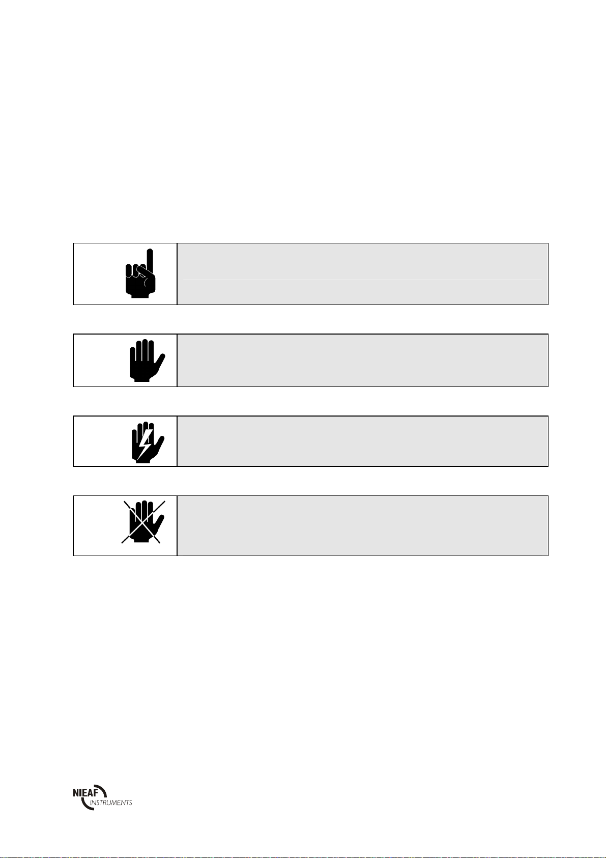
In this user manual, the following four marking conventions are used to focus attention on certain
subjects or actions.
TIP:
gives you suggestions and advice to perform certain tasks easier or handier.
ATTENTION:
a remark with additional information; draws your attention to possible problems.
CAUTION:
the machine may be damaged, if you do not carefully execute the procedures.
WARNING FOR DANGER:
you can (seriously) hurt yourself or seriously damage the product, if you do not
carefully execute the procedures.
- this document is described with the words manual or user manual;
- the test equipment is described with the words tester, instrument or test device;
- values or displayed data is placed between inverted commas for example “230 V”;
- keys or switch positions are placed between angular brackets for example [Start] key.

Utrecht
- Page 3 - Ref. 004
Warranty
Nieaf-Smitt bv guaranties the tester for a period of 6 months.
The period of warranty will be effective at the day of delivery. The warranty clauses and the stipulations
regarding liability in terms of delivery (FME and HE).
© Copyright 1997
All rights reserved. Nothing from this edition may be multiplied, or made public in any form or manner,
either electronically, mechanically, by photocopying, recording, or in any manner, without prior written
constent form Nieaf-Smitt bv.
Nieaf-Smitt bv reserves the right to change parts at any given moment, without prior or direct notification
to the client. The contents of this user manual may also be changed without prior warning.
This user manual is compiled with all possible care, but Nieaf-Smitt bv can not accept any responsibility
for possible errors in this user manual or any consequences resulting from that.
Utrecht
- Page 4 - Ref. 004
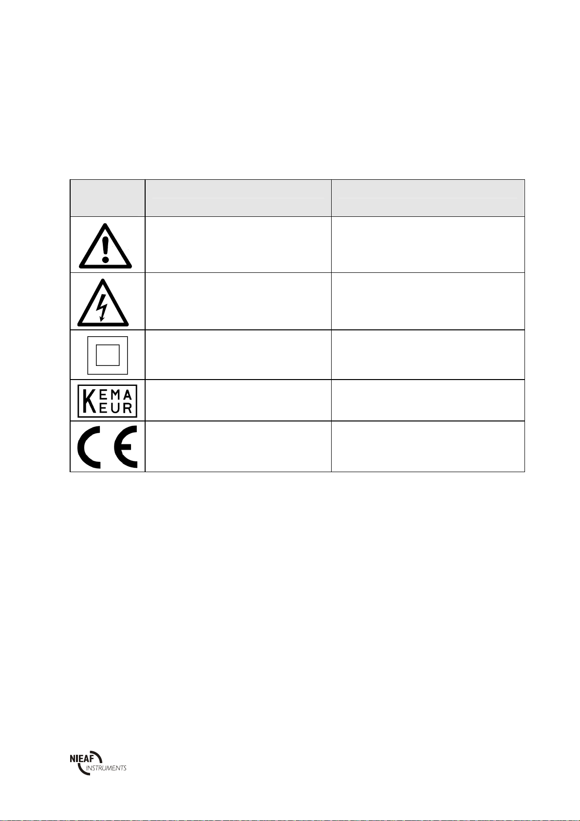
Warning pictograms on the tester
There are a number of pictograms on the tester, meant to warn the user of remaining risks that may be
present in spite of the safe design.
Pictogram
Description Location on the tester
Warning:
General sign for danger. Read the
instructions carefully before use.
At the back side of the tester on the instruction
label.
Warning:
Danger for direct contact with live parts. At the back side of the tester on the instruction
label and under the battery cover.
Mark:
Insulation class II (double insulation). At the back side of the tester on the instruction
label.
Mark:
Marks the KEMA certification of the tester.
The KEMA keur is placed on the front side of
the tester.
CE-mark:
Declares the conformity with the European
Directives.
The CE-mark is placed on the front side of the
tester.
All peripherals, which are used by this tester, must be provided with a CE-mark. For example the use of a PC.
Table 1: Pictograms on the tester

Utrecht
- Page 5 - Ref. 004
CONTENTS
1. GENERAL SAFETY REGULATIONS.................................................................................................................. 7
2. INTRODUCTION ................................................................................................................................................... 8
2.1 GENERAL ........................................................................................................................................................ 8
2.1.1 The intended use...................................................................................................................................... 8
2.1.2 Target group............................................................................................................................................ 8
2.1.3 Working principle.................................................................................................................................... 9
2.2 SPECIFICATIONS ........................................................................................................................................ 10
2.3 CERTIFICATION.......................................................................................................................................... 11
3. TESTER COMPOSITION....................................................................................................................................12
3.1 GENERAL ...................................................................................................................................................... 12
3.2 PRINCIPLE OF MEASUREMENT..............................................................................................................12
3.2.1 Visual inspection ...................................................................................................................................12
3.2.2 Insulation resistance measurement...................................................................................................... 13
3.2.3Lowresistance……….……………………………………………………………………...…………. 14
3.2.4 Beeping..................................................................................................................................................13
3.2.5 Mains Voltage and mains frequency.................................................................................................... 13
4. INSTALLATION; START-UP AND ADJUSTING............................................................................................. 14
5. HOW TO USE THE TESTER ?........................................................................................................................... 15
5.1 OPERATION.................................................................................................................................................. 15
5.1.1 Starting .................................................................................................................................................. 17
5.2 TESTING........................................................................................................................................................ 17
5.2.1 Test 1: Insulation resistance measurement.......................................................................................... 19
5.2.2 Test 2: Low resistance measurement.................................................................................................... 19
5.2.3 Test 3: Beeping the stallation…………………………………………………………….…………...20
5.2.4 Test 4: Voltage / frequency of mains voltage measurement................................................................ 19
5.3 MEMORISING OF RESULTS......................................................................................................................20
5.4 RECALLING OF MEMORISED RESULTS................................................................................................22
5.5 RS232 COMMUNICATION ..........................................................................................................................23
5.6 ERASING OF RESULTS...............................................................................................................................25
5.7 RESET OF THE INSTRUMENT.................................................................................................................. 27
5.8 TROUBLESHOOTING.................................................................................................................................. 28
5.9 CALIBRATION AND REPAIR ..................................................................................................................... 29
6. MAINTENANCE................................................................................................................................................... 30
6.1 BATTERIES REPLACEMENT..................................................................................................................... 30
6.2 CLEANING..................................................................................................................................................... 31
7. ACCESSORY AND REPLACEABLE PARTS..................................................................................................... 32

Utrecht
- Page 6 - Ref. 004
Tables:
Table 1: Pictograms on the tester
Table 2: Switches
Table 3: Sub results and parameters
Table 4: General faults and warnings
Figures:
Figure 1: Operating
Figure 2: Identification number of each function
Figure 3: RS232 connector
Figure 4: RS232 cable
Figure 5: An example of print out
Figure 6: Batteries inserted
Attachments:
Attachment 1: EU-Declaration of Conformity
Attachment 2: Circuit diagrams
- Insulation resistance measurement:
- Insulation resistance of telephone line measurement;
- Floor resistance measurement;
- Insulation resistance of mains installations measurement;
- Insulation resistance of ground cable measurement
- Low resistance measurement
- Voltage / frequency of mains voltage measurement
Utrecht
- Page 7 - Ref. 004
1. GENERAL SAFETY REGULATIONS
It is not allowed to remove, to skirt or to tide over (b
y
hand
y
constructions) the
enclosure or safeties of the tester during normal use.
Method of measurement and range are indicated on the back side of the instrument.
It is not allowed to change or remove the case or protections of the tester during
normal use and without written constent from Nieaf-Smitt bv.
Method of measurement and range are indicated on the back side of the instrument.
It’s forbidden to place and/or to use the instrument in a room where is a risk of
explosion.
If the tester is used by a third party, you being the owner are responsible, unless
otherwise specificated.
Repair can only be done by Nieaf-Smitt bv.
Provide a clean and save workplace which has sufficient lightning.
Utrecht
- Page 8 - Ref. 004
2. INTRODUCTION
2.1 GENERAL
2.1.1 The intended use
The IRT-S is intended for execution of low resistance, voltage and insulation resistance
measurements. If the instrument is used in manner not specified in this user manual, the protection
provided by the instrument may be impaired and the supplier is excluded from any responsibility.
2.1.2 Target group
The target group of people for whom the tester and this user manual are applicable are competent and
technical qualified persons.
Competent persons are persons who:
- have got a certain level of technical knowledge gained by education/training and who;
- have got certain skills required to operate the tester.
Technical qualified persons are persons who:
- are competent and who;
- have got a certain level of technical knowledge gained by education/training and who;
- are familiar with the applied technology in the instrument and are aware of the possible dangers and
risks.
Repair can only be done by Nieaf-Smitt bv.
By operating we mean:
- setting up the instrument and executing tests;
- processing the test results.

Utrecht
- Page 9 - Ref. 004
2.1.3 Working principle
Structure
The IRT-S is a professional microprocessor-controlled instrument, intended for the execution of low
resistance, voltage and insulation resistance measurements. Select the test by means of the rotary
switch. Now the user is able to prescribe the desired measuring method. The test results are clearly
displayed on the LCD.
Connecting
The instrument is powered by four alkaline batteries (4 x 1,5 V IEC). The tester is provided with a on/off
switch and can, after powering up the instrument, be used at once. The test cord or the RS232 cable (data
transfer cable) are connected at the upper side of the tester.
Measuring
Each test has it’s specific circuit diagram which is given in the attachments.
Next measurements are executable by the instrument:
1. The measuring of the Insulation resistance using
- 100 V
- 250 V
- 500 V
- 1000 V
2. The measuring of the low resistance.
3. The measuring of the mains voltage.
4. The measuring of the mains frequency.

Utrecht
- Page 10 - Ref. 004
2.2 SPECIFICATIONS
General
Power supply : 4 x 1,5 V IEC LR14 alkaline batteries
Battery life time : approx. 1200 measurements (1 measurement per 5
minutes)
Display : 3 digit 7 segment LCD 19mm
Quality standard : design, development and production according to ISO
9001
Mass : approx. 0,75 kg including batteries and accessories
Dimensions (wxhxd) : 110 x 65 x 290 mm
Environment and storage
Reference temp. range : 5°C - 35°C
Operating temp. range : 0°C - 40°C
Storage temp. range : -10°C - 60°C
Max. operating humidity : 85% RH (0°C - 40°C)
Max. storage humidity : 80% RH (40°C - 60°C)
90%RH(-10°C - 40°C)
Degree of protection : IP50
Pollution degree : Class II
Over voltage protection : Category II 600V Category III 300V
Testing
Insulation resistance (Riso) using 100 V (0-10%)
Open circuit output voltage : 100 V / 0 - 10%
Measuring current : ≥1 mA at 100 kΩ load
Range (auto range) : 0 - 1,999 MΩ/ 2,00 - 19,99 MΩ/ 20,0 - 199,9 MΩ
Resolution : 0,001 MΩ/ 0,01 MΩ/ 0,1 MΩ
Accuracy : ± 2% of reading ± 2 digits
Short circuit current : ≤1,4 mA
Insulation resistance (Riso) using 250 V (0-10%)
Open circuit output voltage : 250 V / 0 - 10%
Measuring current : ≥1 mA at 250 kΩ load
Range (auto range) : 0 - 1,999 MΩ/ 2,00 - 19,99 MΩ/ 20,0 - 199,9 MΩ
Resolution : 0,001 MΩ/ 0,01 MΩ/ 0,1 MΩ
Accuracy : ± 2% of reading ± 2 digits
Short circuit current : ≤1,4 mA
Insulation resistance (Riso) using 500 V (0-10%)
Open circuit output voltage : 500 V / 0 - 10%
Measuring current : ≥1 mA at 500 kΩ load
Range (auto range) : 0 - 1,999 MΩ/ 2,00 - 19,99 MΩ/ 20,0 - 199,9 MΩ
Resolution : 0,001 MΩ/ 0,01 MΩ/ 0,1 MΩ
Accuracy : ± 2% of reading ± 2 digits
Short circuit current : ≤1,4 mA

Utrecht
- Page 11 - Ref. 004
Insulation resistance (Riso) using 1000 V (0-10%)
Open circuit output voltage : 1000 V / 0 - 10%
Measuring current : ≥1 mA at 1000 kΩ load
Range (auto rang) : 0 - 1,999 MΩ/ 2,00 - 19,99 MΩ/ 20,0 - 199,9 MΩ
Resolution : 0,001 MΩ/ 0,01 MΩ/ 0,1 MΩ
Accuracy : ± 2% of reading ± 2 digits
Short circuit current : ≤1,4 mA
Low resistance
Range : 0 - 20 Ω
Resolution : 0,01 Ω
Accuracy : ± 2% of reading ± 2 digits
Short circuit current : 200 mA at Ubat > 5 V
Open circuit output voltage : > 4,5 V at Ubat > 5V
Limiting value : upper- and lowerlimit are adjustable with sound signal
Voltage
Range : 0 - 440 Veff
Resolution : 1 V
Accuracy : ± 2% of reading ± 2 digits
Frequency
Range : 25,0 - 199,9 Hz / 200- 500 Hz
Frequency : 0,1 / 1 Hz
Accuracy : ± 0,1% of reading ± 1 digit
Transport
The tester is a portable test device which can be hand-held or lay down (solid foundation) during the
tests. Take care of the instrument during transport to avoid any damage.
2.3 CERTIFICATION
The tester and this manual have been designed, constructed and tested according to the European
directives. During all these phases the relevant (preliminary European standards have been taken into
account. The CE-mark has been mounted on the instrument. The directives and the standards mentioned
are enumerated in the EC-Declaration of Conformity.

Utrecht
- Page 12 - Ref. 004
3. TESTER COMPOSITION
3.1 GENERAL
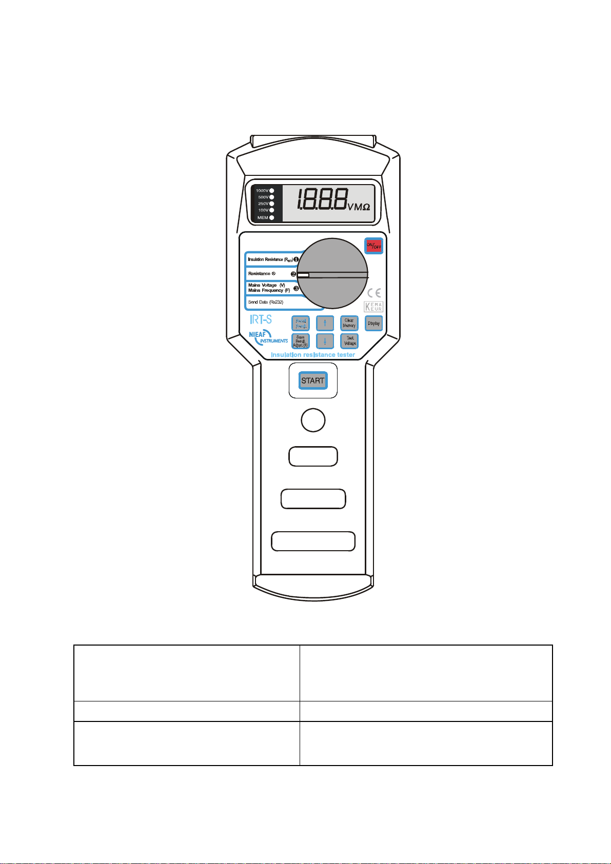
The IRT-S is built in an enclosure of solid ABS plastic. The display is situated at the front side of the
tester. The test results are displayed. The main parts (see figures in Chapter 5) are listed below:
Front:
1. On/off key
2. Rotary switch
3. LCD-display (NR. 13 in the figure)
Back:
1. Instruction label
2. Serial number
3. Battery cover
4. Battery cover fastening screw
3.2 PRINCIPLE OF MEASUREMENT
3.2.1 Visual inspection
Visually check the test object or installation before executing the safety tests. The function of the visual
inspection is to ensure the electrically safety of the latter parts. Check wires, cables and components for
possible damages. If any damage has been noticed, it isn’t allowed to perform any tests before a technical
qualified person has repaired the test object or installation . The visual inspection is executed by the
operator.
Utrecht
- Page 13 - Ref. 004
3.2.2 Insulation resistance measurement
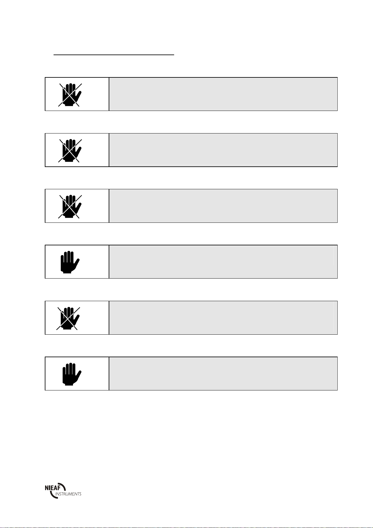
Do not touch the test object or the test cords during the measurement because
hazardous voltage can be present.
This test is intended to check the insulation resistance of a test object or installation. The test can be
executed by four different voltages.
The discharging of the capacitive load is performed automatically after finishing the measurement.
After the measuring of the capacitive object, the discharged voltage will be displayed.
3.2.3 Low resistance
This test is intended to check the low resistance between two terminals of a test object or
installation. The test can be done between different live parts or live - and neutral parts of the
installation or the object.
In order to obtain correct results, first a compensation of the test cords’ resistance must be carried out.
The measurement is automatically carried out in two steps. The first step is executed with the positive
polarity of the test voltage, while the second step is executed with the negative polarity.
The displayed result is an average of both polarities:
Result = Re ( ) Re ( )ss
+
+−
2
Result: displayed value;
Res (+): result obtained with positive polarity (can not be displayed separately);
Res (-): result obtained with negative polarity (can not be displayed separately);
3.2.4 Beeping
The IRT-S is equipped with adjustable limits that can be used as an indication for the value of
the resistance measured. This method is called “beeping” of an object. After setting a minimum and
maximum limit, a sound signal will be produced each time a result is between these limits.
3.2.5 Mains Voltage and mains frequency
This test is intended to check the present voltage and frequency.
The test is executed between the several phases and the zero of the installation

Utrecht
- Page 14 - Ref. 004
4. INSTALLATION; START-UP AND ADJUSTING
The tester can only be used if no damages or defects are noticed and all original
components belonging to the tester are mounted
The transportation and the handling of the tester should be done carefully to prevent
any damage.
This paragraph describes the installation and the starting up procedure of the instrument. The
installation, the starting up and the adjustment of the instrument may be done by competent persons.
1. Unpack the instrument.
Remove the packing materials without causing damages to the environment. Check the tester on
possible damages. If damages are noticed, contact Nieaf-Smitt bv..
2. Put the instrument in a horizontal position, at the workplace or in the test room.
Keep enough clearance around the instrument to facilitate an easy operation, adjustment and
reading of test results, without any problems or extra danger.
3. Insert the batteries in the instrument.
4. Connect the test object according to the circuit diagrams with the IRT-S.
5. Carry out the selected test.
Find a place to put the manual such that it is within reach during the
use of the instrument.

Utrecht
- Page 15 - Ref. 004
5. HOW TO USE THE TESTER ?
5.1 OPERATION
1. On/off key
2. Rotary switch
3. Clear memory key
4. DISPLAY key
5. Test voltage key
6. START key
7. Decrease key of memory location
8. Save result key to save the measuring results
9. Recall result key to recall the measuring results
10. Increase key memory location
11. Memory indication LED
12. LED’s rated test voltages
13. LCD Display
12. Connection (functional and RS232)
1. Instruction label
2. Serial number
3. Battery cover
4. fixing screw for battery cover
5. Plastic cover of the locking screw
6. Locking screw covered by a rubber foot
Figure 1: Operating

Utrecht
- Page 16 - Ref. 004
Keys
Function key description.
Selector position
Description
On/off
Recall result
Save result
Adjust (R)
↑
↓
Clear memory
Test voltage
Display
Insulation resistance
(RISO)
Resistance (R)
Mains voltage (V) /
Mains frequency (f)
Send Data (RS232)
- to switch on/off the tester; the tester will switch off automatically after it hasn’t
been used for ten minutes or more;
- to recall the saved results;
- to save the displayed measuring results;
- to compensate the test cord resistance in the [R] function (low resistance);
- to increase/decrease the object or measuring place identification number when
saving or recalling the results;
- to check, in the [Recall Result] function, other results which have been saved
later than the displayed one under the same object and measuring place
identification number;
- to clear all saved results;
- to clear all saved results under a certain object identification number
(without dots YYY);
- to clear the saved results under a certain measuring place identification number
only (with dots XXX);
- to clear, in the [Recall Result]-function, the displayed result only;
- to execute a RESET of the instrument.
- select the rated test voltage
- display results;
- to select, in the [Save Result] or in the [Recall Result]-function, the object
identification number or measuring place identification number;
- insulation resistance measurement;
- to measure the low resistance;
- to measure the voltage and/or mains frequency;
- to transfer stored data to the printer or to the PC.
Table 2: Switches
Utrecht
- Page 17 - Ref. 004
5.1.1 Starting
Operating the instrument may only be done by competent persons.
Never open the instrument during thre esting.
Check before every test:
* cables and test cords on possible damages;
* tester on possible damages and/or defects.
1. Check the instrument on visible damages and/or defects, for example the power plug, the line
cord etc. .Don’t carry out any test with a damaged or broken instrument. Provide skilled
reparation first
2. Do not connect the test object as well as the test cords with the tester.
3. The instrument can be used at once.
Test selection
First carry out a visual inspection on the test object or the installation. Connect the tester conform the
circuit diagrams of attachment 2.
We have three different tests:
Test 1: the measuring of the insulation resistance.
Test 2: the measuring of the low resistance.
Test 3: the measuring of the mains voltage and/or the mains frequency.
5.2 TESTING
-Avoid testing objects or installations under the influence of high electromagnetic
and/or electrostatic fields.
In the following paragraph the test methods will be explained. We consider that the starting-up is
carried out as described in paragraph 5.1.1.
Utrecht
- Page 18 - Ref. 004
5.2.1 Test 1: Insulation resistance measurement
-Do not disconnect the test cords during the measurement, because measured object
can stay charged => dangerous;
-Do not touch the object or test cords during the measurement => hazardous voltage
can be present;
-Each result can be saved only once.
How to carry out test 1:
1. Connect the test cords with the instrument conform the circuit diagram of attachment 2.
2. Set the rotary switch to [insulation resistance RISO].
3. Select the nominal test voltage using the [Test voltage] key.
4. Press the [Start] key and release it.
5. The result is displayed. Read out the result, save it if required, and note the memory codes when
necessary.
6. Disconnect the test object or carry out another measurement.
5.2.2 Test 2: Low resistance measurement
- First carry out compensation.
- Displayed result is an average of both (+ , -) polarities.
- Each result can be saved only once.
First carry out compensation:
1. Set the rotary switch to [low resistance R] to test the low resistance.
2. Connect the test cords to the instrument and cross the measure tips (make sure the contact is well
done).
3. Press the [Save result / Adjust (R)] key and release it. If the the test cords are well compensated,
0.00 6should be displayed.
4. Now the lights are going to burn near “Lead Adjust”.
How to carry out test 2:
5. Connect the test cords with the instrument conform the circuit diagram of attachment 2.
6. Check if the rotary switch is set to [Resistance (R)].
7. Press the [Start] key and release it.
8. The result is displayed. Read out the result, save it if required, and note the memory codes when
necessary.
9. Disconnect the test object or carry out another measurement.
Utrecht
- Page 19 - Ref. 004
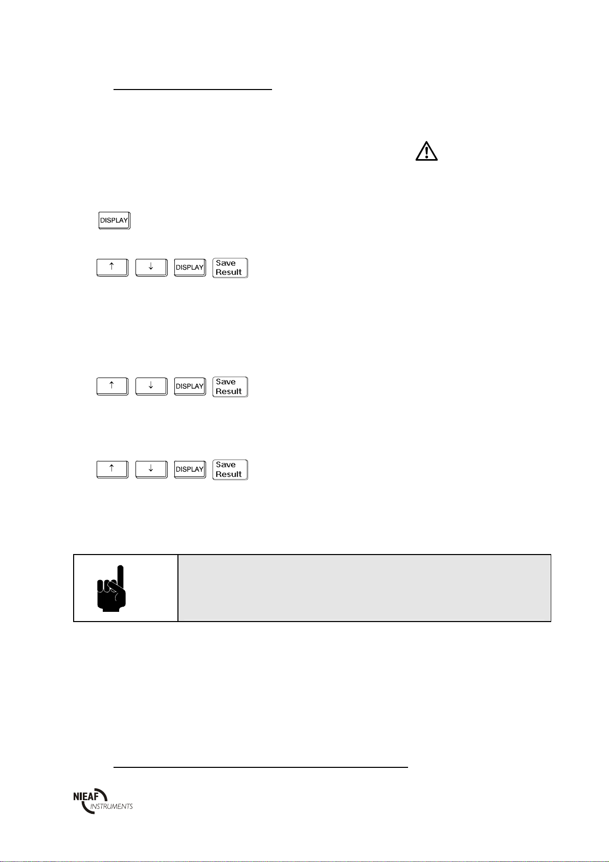
5.2.3 Test 3: Beeping the installation
A beep sound can be used as an indication for a good result in low resistance measurement (also
paragraph 3.2.4). A signal will be produced every time the measurement result will be between the
upper and lower resistance limits.
In case the result falls outside the limits, no sound is produced and the sign is shown next to the
result.
1. - ON or OFF is displayed according to the current
value of the buzzer status (in the second case the
BUZ text lasting 2s precedes the OFF text).
2. ,, , - Set the buzzer status ON or OFF using [↑],[↓]
keys.
- To confirm selection, press [SAVE] key or
press [DISPLAY] key to continue without change.
- In case the ON status is selected, LO text is shown
for 2s and the current value of the LOW limit is
shown afterwards.
- If the OFF status is selected the instrument exists
this procedure and --- is displayed.
3. ,, , - Set LOW limit using [↑],[↓] keys.
- To confirm the new limit value, press [SAVE]
key or press [DISPLAY] key to continue without
change.
- HI text is shown for 2s and the current value of
the HIGH limit is shown afterwards.
4. ,, , - Set HIGH limit using [↑],[↓] keys.
- To confirm the new limit value, press [SAVE]
key or press [DISPLAY] without change.
Afterwards --- is displayed.
The LOW limit can not exceed the HIGH limit.
If the operator makes a wrong selection, the limit values are
automatically adjusted to satisfy this rule.
5.2.4 Test 4: Voltage / frequency of mains voltage measurement

Utrecht
- Page 20 - Ref. 004
Max. allowed input voltage is 440 Volts.
How to carry out test 3:
1. Connect the test cords with the instrument conform the circuit diagram of attachment 2.
2. Set the rotary switch to [Mains voltage (V) / mains frequency (f)].
3. The result will be displayed without pressing the [Start] key. The displayed value is the present
voltage.
4. Press the [Display] key to display the mains frequency.
5. Save the result if required, and note the memory codes when necessary.
6. Disconnect the test object or carry out another measurement.
5.3 MEMORISING OF RESULTS
Each saved result is equipped with an identification code defined by the customer. The code consists
of 2 x 3 characters as follows:
Where X.X.X represents a code of a certain measuring place inside the tested object, and YYY.
represents a code of the tested object. Remark: X.X.X is at least one level higher than YYY. For
detailed information we refer to the manual delivered with the PATS-W Administration-Software.
Table of contents


