Starrett 3840 Series User manual

TECHNICAL SUPPORT: (201) 962-8352
1
3840 Series
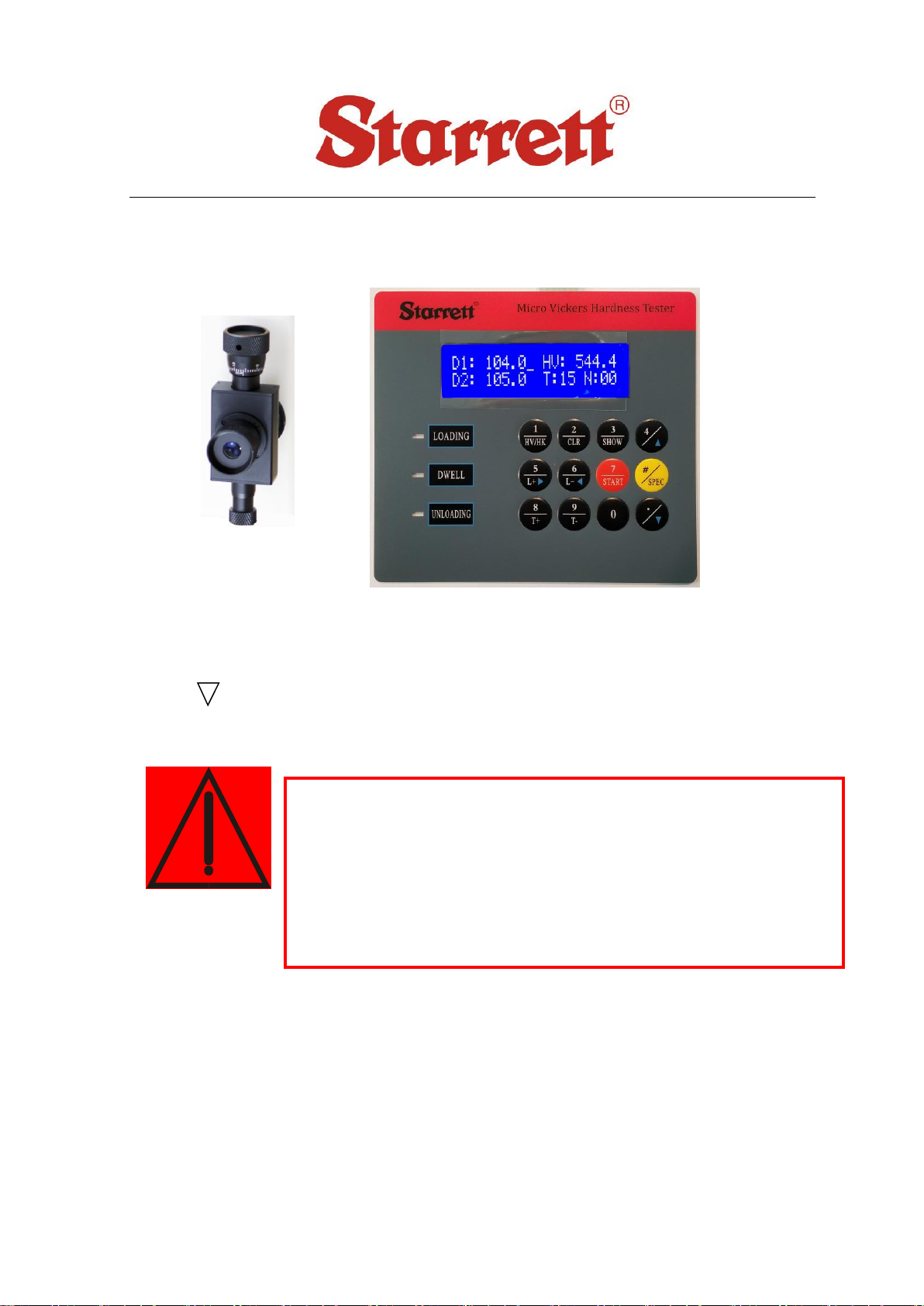
Micro Vickers/Knoop Hardness Tester

TECHNICAL SUPPORT: (201) 962-8352
2
Contents
1. Introduction
2. Main Technical Specifications
3. Installation and Regulation of the Instrument
3.1 Operational conditions
3.2 Unpacking and installation
3.3 Introduction to the operating board and its function keys
4. Usage of the Instrument
5. Calibration and Precautions of the Instrument
6. Accessories (The Packing List)
7. Optional Accessories

TECHNICAL SUPPORT: (201) 962-8352
3
1Introduction
Our advanced line of Micro Vickers Series hardness testers are state-of-the-art,
precise testing systems suitable for hardness analysis of metallic specimens in
metallography laboratories or production environments.
The Starrett micro-Vickers hardness testers are versatile and user-friendly
systems, designed for the accurate hardness testing of small precision parts, thin
materials, coatings, wires and case depth determinations. The 3840 series is our
entry level micro-Vickers hardness tester, covering the load range from 10g to
1kg.
Using guidelines to ASTM E-384/92 Vickers hardness testers standards, the 3840
Vickers hardness tester will offer unmatched repeatability. This micro Vickers
hardness tester can also measure Knoop hardness after installing an optional
knoop indenter. A perfect rugged performer suited for any environment, the
Starrett Vickers hardness testers are offered with a 1 year warranty and free
lifetime technical support.
2Technical Specifications
Test forces 0.098N(10gf), 0.245N(25gf), 0.49N(50gf), 0.9807N(100gf),
1.961N(200gf), 2.942N(300gf), 4.903N(500gf), 9.807N(1kgf)
Displayed Value Tolerance:See Table 9
Test Force Application Method: automatic loading and unloading
Amplification of the Microscope: 400× (for the measurement),
100× (for observation)
Dwell time of the test force: 0~60s (5 second as a unit)
Min. graduation value of the testing drum wheel: 0.25μm/grid
Max. height of the specimen: 70 mm
Distance between the center point of the indenter and the exterior panel: 98mm
X-Y Table Graduation: 25mm x 25mm
Weight: 55 lbs (25kg)
Power source: AC110V/50~60Hz
Overall dimension (L×W×H): (415×295×503)mm

TECHNICAL SUPPORT: (201) 962-8352
4
3 Unpacking, Operational Conditions and Installation
Unpacking and Installation
Cut the belt on packing crate; remove the anti-shock cushion and remove the
instrument and the accessories kit from the crate.
Place the instrument on the prepared solid working table; (for the
construction of the working table, see Fig 1)
IMPORTANT!
Do Not Discard Shipping Crate as This May
be Needed for Future Transportation.
General Safety Instructions
1. Never use clamps, straps, any other tooling or equipment to mount specimen to
the tester anvil.
2. Always use the proper anvil supplied.
3. Be sure to use proper indenter and weight for material and hardness to be tested.
180
300
φ80
Fig.1
TECHNICAL SUPPORT: (201) 962-8352
5
Hardness Tester Maintenance
1. Consult operation instructions for specific maintenance and adjusting procedures.
2. Keep the tool clean for best results.
3. Remove adjusting tools and wrenches. Form habit of checking that adjusting tools
are removed before using machine.
4. Keep all parts in working order. Check to determine that the parts will operate
properly and perform their intended function.
5. Check for damaged parts. Check for alignment, binding, breakage, mounting and
any other condition that may affect tool's operation.
6. Part that is damaged should be properly repaired or replaced. Do not perform
makeshift repairs. (Use the parts list provided to order replacement parts.)
Operating Conditions:
The 3840 series Micro Vickers Hardness Testers are a precise yet sensitive
instrument that should be handled with care. Please be sure to mount on a sturdy
bench in a clean temperature-controlled room for best results. This instrument
should be perfectly level before performing any tests.
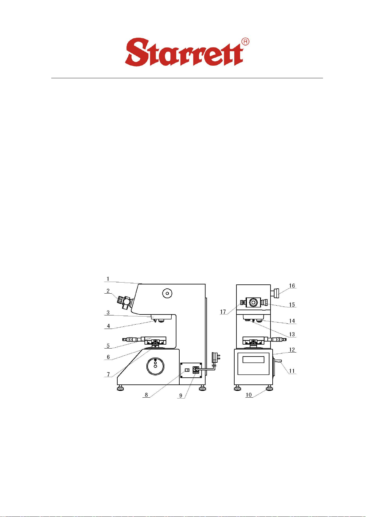
Fig.2
1. Upper Cover 2. Microscope 3. Rotating Plate 4. Indenter 5. Cross Testing Table
6. Up and Down Lead Screw 7. Screw 8. Power Switch 9. Power Cord and Fuse
10. Leveling Feet 11. Hand Wheel 12. Screen 13. 10× Objective 14. 40× Objective
15. Right Drum Wheel 16.Load-Change Hand Wheel 17. Left Drum Wheel

TECHNICAL SUPPORT: (201) 962-8352
6
Set Up –Installation:
Take out the 4 Leveling Feet (10) from the accessories kit and screw them in
the holes on the base panel of the instrument. Unpack the gauze band wrapped
on the Up and Down Lead Screw (6) and Hand Wheel (11) (Fig.2).
Gently remove the anti-shock paper on the indenter with both the hands. Clean
the indenter gently with rubbing alcohol.
Open the Upper Cover of the machine and remove the two Anti-Shock Screws as
shown in Fig.3.
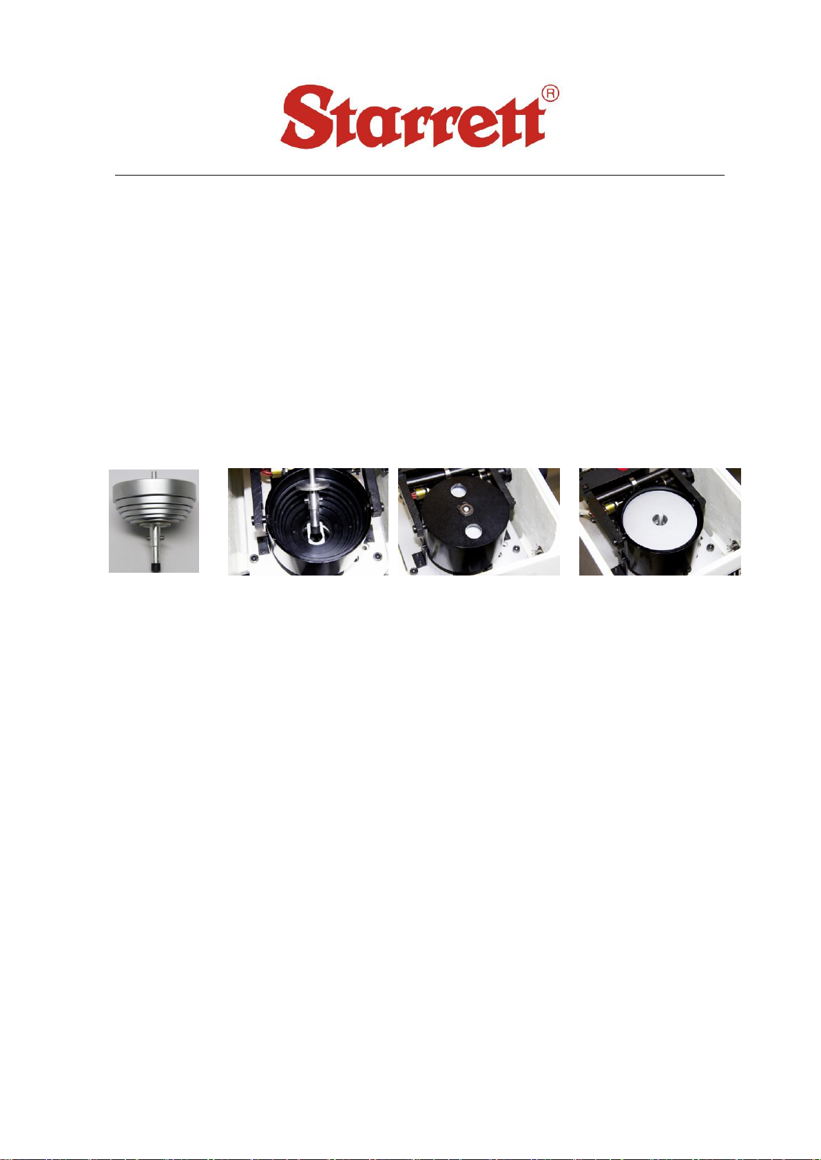
Remove the protective paper on the
Weight Seat and remove the Weight
Seat Cover. Take the Weight shaft
(21) and Weights (22) out of the
accessories kit and clean them
thoroughly. (Clean the supporting
surface of the Weight Axis with cloth
dipped with some oil so as to protect
it against rust.) Put the six Weights
on the Weight Axis in the order from
small to big (see Fig 4).
Fig.3
21.Weight Shaft 22.Weights
23.Weight Shaft Peg 24. V-Shaped Groove
Fig.4
TECHNICAL SUPPORT: (201) 962-8352
7
Hold the top of the Weight shaft, put the Weight shaft into the Weight
Seat and rotate the Weight shaft so that the Weight shaft Peg (23) may
fall into the V-shaped Groove (24) of the lever.
Cover the Weight Seat with the Weight Seat Cover.
Rotate the Load-Change Hand Wheel (16) of testing force, so as to
make the Weight Seat move up and down smoothly on the groove;
Take the dust-protecting cover of the eyepiece tube out and insert
the Microscope (2) into the hole of eyepiece tube until its flush.
Take the X-Y Slide (5) out of accessories kit and clean off the rust
protecting oil on it.
Insert the shaft of the X-Y Stage into the hole on the Elevating Lead
Screw and tighten it with the Screw (7).
Take the supplied bullseye level out of the accessories kit and put it
on the X-Y slide, and then adjust the leveling feet accordingly.

TECHNICAL SUPPORT: (201) 962-8352
8
KEYPAD FUNCTIONS: (Fig.5).
Fig.5
Upper key:Digit 2
Lower key:Zero setting key, press this key to set the zero to digit.
2
CLR
Upper key: Digit 1
Lower key: The shifting key between Vickers and Knoop hardness
1
HV/HK
Upper key:Digit 8
Lower key:Time adding key, every pressing adds 5 seconds
8
T+
Upper key:Digit 9
Lower key: Time deducting key, every pressing shorten 5 seconds
9
T-
Upper key: Digit 5
Lower key: addition key for the luminosity of light source.
5
L+

TECHNICAL SUPPORT: (201) 962-8352
9
Upper key:Digit 6
Lower key: reduction key for the luminosity of light source.
6
L-
Upper key: Radix point.
Lower Key: After press SPEC key, press this key to let the Lower keys
become valid and the cursor will disappear.
·
#
SPEC
Double pressing this key means confirmation. For example: after key in D1
value 202, double press this key to confirm D1. As same, after key in D2
value 203.5 double press this key to confirm D2. The hardness value on the
screen will be “HV: 721.4”.
SPEC key is special function key. Single press this key, then press
key to let Upper keys become valid. And as the same, single press SPEC
key, then press
key to let Lower keys become valid.
Upper key: Digit 4.
Lower key: After press SPEC key, press this key to let all Upper
keys (digit keys) become valid and the cursor will blink.
4
7
START
Upper key: Digit 7.
Lower Key (Start key): Press this key to start the motor and apply test
force.

TECHNICAL SUPPORT: (201) 962-8352
10
4Usage of the Instrument
Slowly, gently rotate the Load-Change Hand Wheel to make the testing force
meet the requirements of the application.
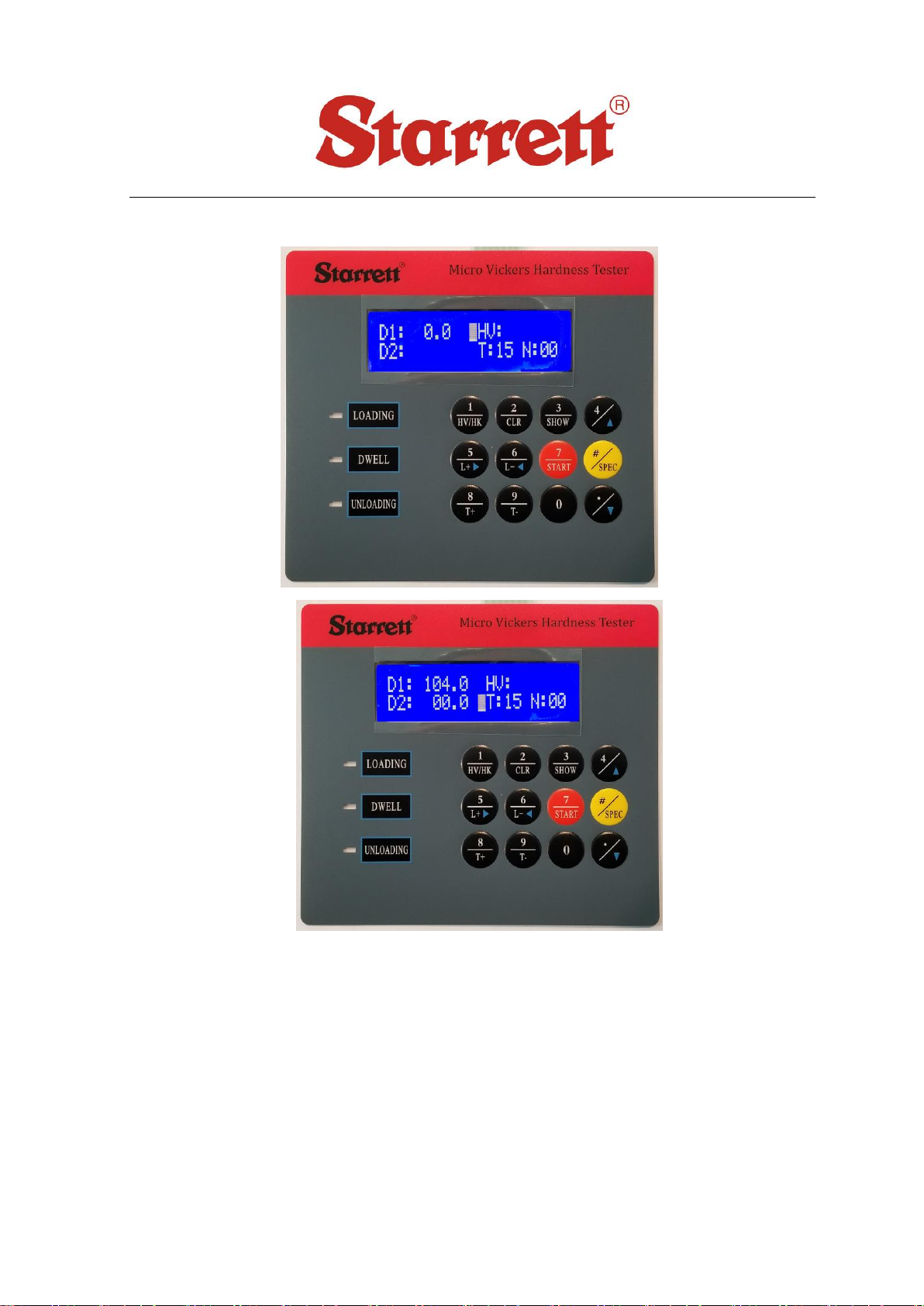
Turn the Power Switch (8) on and the Screen (12) will show the Model of
hardness tester and then will display the main testing screen as shown below.
Adjusting Light Source: Press the “L+” or “L-” buttons to adjust the
brightness for your optimal vision.
Dwell Time Setting: The 900-390- is preset at 15 seconds since this is the
most common time needed for a micro Vickers test. You can adjust this time
by pressing the “T+” or “T-“ buttons. Each button press will add or subtract 5
seconds from the preset time.
Setting the Eyepiece: Turn the Rotating Plate (3) to make the 40×objective
(14) face in the front direction. The general amplification is 400×(The
eyepiece, objectives and specimen are in the focusing state).
Taking a Test: Place the supplied hardness test block or a known specimen
on the Testing Table and then rotate the Hand Wheel to raise the Testing Table.
Look through the Eyepiece to observe. When the hardness block or the
specimen comes into the distance of 1~2 mm under the Objective, at this
point, in the center of the vision field of the Eyepiece appears a bright spot,
which shows it is very close to the focusing plane. At this time, continue
raising the Testing Table up slowly until the hardness block or specimen
surface forms a clear image in the Eyepiece. If two moveable graduated lines
observed in the vision field of the Eyepiece seem vague, turn the eye guard on
the Eyepiece to bring into clear focus. You should now see the grain of the
block very clearly.
Turn the Indenter to the front direction of instrument. At this point, the
distance between the tip of Indenter and the plane of specimen is about
0.4~0.5 mm.
D1: 0.0 HV:
D2: T:15 N:00
TECHNICAL SUPPORT: (201) 962-8352
11
IMPORTANT! When testing an irregular-shaped specimen, take care not to
damage the indenter when turning the turret.
Press the red START button and the instrument will begin by putting the load
on. The red light by the Loading sign on the left side of the keypad will blink.
After the load has completed, the (Dwell) LED lights up, and at this time the
dwell time begins counting down to “0”. After the dwell time of test force is up,
the (Unloading) LED blinks, and the instrument automatically unloads the
testing force. The instrument will beep when this is done.
Measuring the Indentation:
Turn the 40×Objective to face in front direction, observe the indentation in the
eyepiece; rotate the Hand Wheel to focus microscope until the image quality
of indentation becomes clear.
Rotate the Left Drum Wheel (17) as shown above to enable the inner side of
left graduated line tangent to the left tip of the diagonal line of the indentation.
Rotate the Right Drum Wheel (15) as shown above to enable the inner side of
right graduated line tangent to the right tip of the diagonal line of the
indentation (Fig.6).
Each rotation or cycle of the Right Drum Wheel is 50 grids. If it turns 4 cycles
and over 2 grids, that means 50×4+2=202 grids. This is the number that you
will be entering on the display using the keypad.
Once the measurement explained above has been obtained, you must now
press the “SPEC” key and “ “ key, the cursor will blink and now ready for
values to be entered. See picture below:
Fig.6
TECHNICAL SUPPORT: (201) 962-8352
12
Key in digit 202, then press “SPEC” key TWICE to confirm D1 value. The cursor
will move to D2 and is ready for the second measurement.
TECHNICAL SUPPORT: (201) 962-8352
13
Turn the Eyepiece by 900.Measure the other diagonal line length the same
way you did the first measurement. Key in digit 203.5; double press “SPEC”
key to confirm D2 value. The screen will show hardness value automatically:
“HV: 721.4”.
If the operator is not sure of the correctness of present measurement, please
key in D1 and D2 values (grids) again.
After this measurement is completed, press the “SPEC” key; then press the
“ ” key to let the cursor disappear. The instrument is now ready for the next
test.
If you find the Indenter does not face in front direction after you
pressed “START”, it is prohibitive to turn the Rotating Plate(turret)
until the loading, dwelling and unloading process is completed.
(3 LED’s are all out). Only when the entire testing cycle has
completely finished, the position of the Indenter can be changed,
otherwise, the instrument will be damaged.

TECHNICAL SUPPORT: (201) 962-8352
14
5Calibration and Precautions
The Eyepiece
If the graduated lines observed in the vision field of the Eyepiece are
blurry or not clear, you should adjust the clarification by slightly turning
the eye guard in front of the eye piece accordingly.
The Eyepiece should be inserted to the bottom of eyepiece tube with no
space between them, otherwise it would affect the correctness of the
measurement.
When a larger vision field on the specimen is observed, turn 10×Objective
to face in front direction of instrument. At this time, the general
amplification is 100×and it is for observation purposes only.
If the indention observed from the Eyepiece is too small or too large and it
would affect the measurement accuracy, please select new test force again
to meet the needs of requirement for measurement and repeat the test.
Due to the difference of surface roughness and flatness on the specimen,
the indentation may be deformed, therefore, two diagonal line length of
indentation should be measured in two mutually perpendicular
directions.
When testing the Knoop hardness value, only the long diagonal line length
of indention should be measured. The Knoop hardness value (HK) will be
displayed directly.
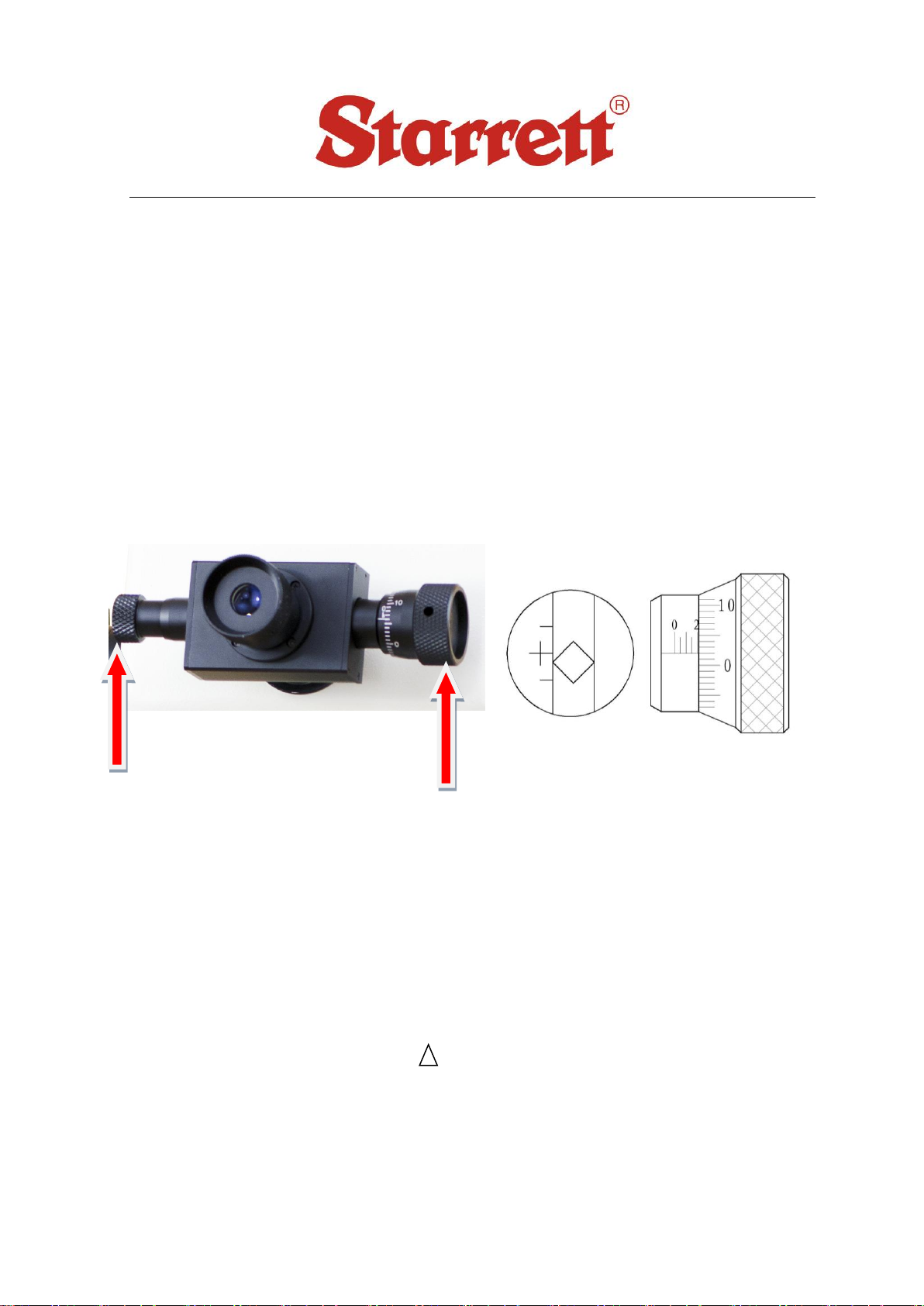
Calibrating the eye piece:
The zero position of the Eyepiece was calibrated before the instrument
was re-crated. During usage over time, it may be the cause of an error,
therefore, zero position setting should be carried out periodically. As soon
as an error appears, the zero position shall be regulated.

TECHNICAL SUPPORT: (201) 962-8352
15
Regulation Method: Turn the Drum Wheels to enable inner sides of
two graduated lines to come close together until the point that no light is
visible between them. This doesn’t mean one line on top of the other. Its
more like one line is to the side of the other. The “0” positions of Right
Drum Wheel also should be aligned as well. If the “0” positions are not
aligned, loosen the screw, align the zero positions, then fasten the screw
(Fig.7).
Fig. 7
The Indenter
The diamond Indenter and indenter axis are important parts of the
instrument, and hence it is necessary to take care not to collide with the
Indenter during the operation.
In order to assure the precision of the measurement, it is important to
keep the Indenter clean. If it is covered with grease or dust, it should be
cleaned carefully with absorbent cotton dipped with rubbing alcohol.
The round column of the Indenter is marked with a red dot. When
changing the indenter, take care to make the red dot face the front
direction when it is reloaded, and the focus of the diagonal lines of the
indentation should be aligned with the red dot. It is possible to make the
alignment of the cross-shaped line in the eyepiece with the diagonal lines
of the indentation. If the indentation observed is not aligned with the
cross-shaped line, please unscrew the screw on the Indenter, turn the
Indenter a bit and the fasten the screw, and then make the alignment
again through tests until the alignment is all right to your satisfaction (See
Fig.8)
Fig.8
Loosen the screws and
align “0”positions again

TECHNICAL SUPPORT: (201) 962-8352
16
Usage Method of Knoop (HK) Hardness
Sample Introduction of Knoop Hardness
The distinguishing characteristic of Knoop test is the improvement on the
indenter’s design. You only need to measure the long diagonal line length of
indentation, therefore the relative error of measurement becomes smaller.
Compared to the micro Vickers test, when press the test force with same value, the
indentation of a Knoop hardness test is shallower, hence, it is suitable to test the
thin sheet parts. It is used to test brittle and hard materials such as enamel, glass,
agate, man-made precious stone, ceramic metals, etc.
Usage of Hardness Tester
When replacing the Knoop indenter, the red point on the outer cylinder of indenter
should face to front of the machine (see Fig.9).
Operate the key on operation board to enable the testing
method change to “HK”, the Knoop hardness test
method.
7.2.3 The operation method is just as same as that of micro Vickers
hardness test, see Section 4.
7.2.4 Only required to measure the long diagonal line length of the indentation; then
input the read digit. The Knoop hardness value (HK) will be displayed on the
screen.
D1: 0.0 HK:
T:10 N:00
Fig.9
Fig.9

TECHNICAL SUPPORT: (201) 962-8352
17
Hardness
Symbol
Max Allowed Tolerance of Display Value ±%
Hardness HV
50
100
150
200
250
300
350
400
450
500
600
700
800
900
1 000
1 500
HV 0.01
HV
0.015
10
HV 0.02
8
HV
0.025
8
10
HV 0.05
6
8
9
10
HV 0.1
5
6
7
8
8
9
10
10
11
HV 0.2
4
6
8
9
10
11
11
12
12
HV 0.3
4
5
6
7
8
9
10
10
11
11
HV 0.5
3
5
5
6
6
7
7
8
8
9
11
HV 1
3
4
4
4
5
5
5
6
6
6
8
HV 2
3
3
3
4
4
4
4
4
5
5
6
HV 3
3
3
3
3
3
4
4
4
4
4
5
HV 5
3
3
3
3
3
3
3
3
3
4
4
HV 10
3
3
3
3
3
3
3
3
3
3
3
HV 20
3
3
3
3
3
3
3
3
3
3
3
HV 30
3
3
2
2
2
2
2
2
2
2
2
HV 50
3
3
2
2
2
2
2
2
2
2
2
HV 100
3
2
2
2
2
2
2
2
2
2
1 When the indentation diagonal length is less than 0.020 mm, the table will not display the value.
2 For intermediate values, the maximum allowable error can be obtained by interpolation.
3 When the Micro Hardness Tester value in the table is 0.001mm or indentation diagonal length of the
average of 2% of the maximum permissible error given, please select the higher value.

TECHNICAL SUPPORT: (201) 962-8352
18
7.3 The Max. Allowed Tolerance of Displaying Value
Hardness
Scale
Test
Force(N)
Max Allowed Tolerance of Display Value %
Hardness Value(HK)
50
100
150
200
250
300
350
400
450
HK0.01
0.098
5
6
7
9
9
10
11
-
-
HK0.025
0.245
5
5
5
6
6
7
7
8
8
HK0.05
0.49
5
5
5
5
5
5
5
6
6
HK0.1
0.98
5
5
5
5
5
5
5
5
5
HK0.2
1.961
5
5
5
5
5
5
5
5
5
HK0.3
2.942
5
5
5
5
5
5
5
5
5
HK0.5
4.903
5
5
5
5
5
5
5
5
5
HK1
9.807
5
5
5
5
5
5
5
5
5
The specimen
The surface of the specimen must be clean or penetration and/or
measuring results may be distorted. Please clean the specimen with
alcohol or other safe cleaner.
When thin filaments, thin pieces and small parts are used as the
specimens, the fine wire testing table, thin specimen testing table and the
fork-shaped testing table should be used to hold the specimens
respectively on the X-Y SLIDE for the measurement. If the specimen is too
small to be held by the testing table, the specimen should be inlayed and
polished for the measurement.

TECHNICAL SUPPORT: (201) 962-8352
19
5Packing List:
The main instrument (including a micro Vickers Indenter, a 40X Objective and
a 10X Objective)
Item
Descriptions
Quantity
1
Weights
6 PCS
2
Weight Shaft
1 PC
3
Cross Testing Table
1 PC
4
Thin Specimen Testing Table
1 PC
5
Fork-Shaped Testing Table
1 PC
6
Fine Wire Testing Table
1 PC
7
Screw Drivers
2 PCS
8
Leveling Feet
4 PCS
9
Bullseye Level
1 PC
10
Power Cord
1 PC
11
Prepare Fuses (1A)
2 PCS
12
10×Digital Micro Eyepiece
1 PC
13
Vickers Hardness Blocks
2(one mid range
HV0.2 block and one
high HV1 block)
14
Operation Manual
1 PC
Other Starrett Test Equipment manuals

Starrett
Starrett SR160 User manual

Starrett
Starrett SR300 User manual

Starrett
Starrett SR160 User manual

Starrett
Starrett MTH-330 User manual

Starrett
Starrett MTH-550 User manual

Starrett
Starrett MTH-110 User manual

Starrett
Starrett SR200 User manual

Starrett
Starrett SR160 User manual

Starrett
Starrett DFC-2 User manual
Popular Test Equipment manuals by other brands

Progressive Electronics
Progressive Electronics PE395 instruction manual

Viavi
Viavi IFR 6000 Operation manual

Martindale Electric
Martindale Electric HANDYPAT HPAT500 instruction manual

MULTILANE
MULTILANE AT4039EML user guide

TESTING
TESTING RA 100 Concrete operating manual

Wetekom
Wetekom Scan 20000 instructions


