manuals.online logo
Brands
  1. Home
  2. •
  3. Brands
  4. •
  5. StarTech.com
  6. •
  7. Extender
  8. •
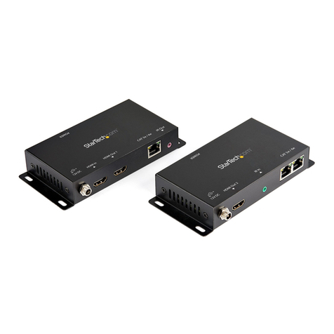
  9. StarTech.com POEEXT1GAT User manual

StarTech.com POEEXT1GAT User manual

Instruction Manual
DE: Bedienungsanleitung - de.startech.com
FR: Guide de l'utilisateur - fr.startech.com
ES: Guía del usuario - es.startech.com
IT: Guida per l'uso - it.startech.com
NL: Gebruiksaanwijzing - nl.startech.com
PT: Guia do usuário - pt.startech.com
Manual Revision: 08/31/2021
For the most up-to-date information, please visit: www.startech.com
Packaging Contents
• 1x Gigabit Power over Ethernet Extender
• 1x Instruction Manual
System Requirements
• RJ45 terminatedCAT5orhigherEthernet cabling(“Solid”UTP cable
recommended)
• 10/100/1000 MbpscompatiblePoweroverEthernetnetwork and/or
devices(PoE/PoE+)
• PoEdevicesmustcomplywithIEEE802.3ator802.3afstandards
Note:Total extensiondistancescanoften beshorter duetopower
delivery voltage-drop ontheconnectedcables.Maximum distances can
vary basedonthequalityoftheUTP cablesandtheenvironment.
Product Overview
Input Side
Output Side
POEEXT1GAT
Gigabit Power over Ethernet Extender 802.3at / 802.3af - 330ft (100m)
LEDs
10/100/1000
PoE+ RJ45
Input Port
10/100/1000
PoE+ RJ45
Output Port
LED Indicators
LED Indication
PoE IN (Green) Solid: Indicates that the port is
providing 52-56V (802.3at) / 48V
(802.3af) DC in-line power (PSE is
connected)
Port Function
IN Port (Input)
Connect the PoE IN port from a
802.3at / 802.3af Power Sourcing
Equipment (PSE) device through CAT5
or higher Ethernet cabling:
• PoE injector
• PoE injector hub
• PoE switch
• Another POEEXT1GAT in a daisy
chain conguration
OUT Port (Output)
Connect the PoE OUT port to a 802.3at
/ 802.3af PoE powered device (PD)
through CAT5 or higher Ethernet
cabling:
• PoE camera
• PoE wireless access point
• PoE splitter
• Another POEEXT1GAT in a daisy
chain conguration
Installation
The PoE Extender supports 10Mbps, 100Mbps and1000Mbps network
speedsand willautomatically detectthespeed ofthe incoming
connection.
Beforeinstallation, checkyour networkinfrastructure. If there are any
IEEE 802.3at /802.3af devicesthat require power, the PoE Extender
can provide power and data Ethernet connectivity conveniently, and
easily.
The PoE Extender should be installedbetween thePSE (Power Source
Equipment) andthe PD (PoweredDevice). It is powered by PSEand
forwards the Ethernetdata andremaining PoE powerto thePD.
ThePoEextenderdoes not requireanexternal powersupply and
willinjectpowerto thePDs without aectingdata transmission
throughput.
Port Connections
Thereare twoRJ45 ports on the PoE Extender.The“IN”port functions
as“PoE (Dataand Power) input”and the“OUT”port functions as“PoE
(Dataand Power) output”.
LNK/ACT (Green)
Solid: Indicates that a port link is
established (PSE link is detected)
Blinking: Indicates that the PoE
Extender is actively sending or
receiving data over the IN port
(activity)
PoE OUT (Orange) Solid: Indicates that the port is
providing 52-56V (802.3at) / 48V
(802.3af) DC in-line power (PD is
connected)
FCC Compliance Statement
This equipment has been tested and found to comply with the limits for a Class A digital device, pursuant to Part 15 of the FCC rules.These limits are designed to provide reasonable protection against
harmful interference when the equipment is operated in a commercial environment. This equipment generates, uses and can radiate radio frequency energy and, if not installed and used in accordance
with the instruction manual, may cause harmful interference to radio communications. Operation of this equipment in a residential area is likely to cause harmful interference in which case the user will
be required to correct the interference at his own expense.
This device complies with part 15 of the FCC Rules. Operation is subject to the following two conditions: (1)This device may not cause harmful interference, and (2) this device must accept any
interference received, including interference that may cause undesired operation.
Changes or modications not expressly approved by StarTech.com could void the user’s authority to operate the equipment.
Industry Canada Statement
This Class A digital apparatus complies with Canadian ICES-003.
Cet appareil numérique de la classe [A] est conforme à la norme NMB-003 du Canada.
CAN ICES-3 (A)/NMB-3(A)
Use ofTrademarks, Registered Trademarks, and other Protected Names and Symbols
This manual may make reference to trademarks, registered trademarks, and other protected names and/or symbols of third-party companies not related in any way to
StarTech.com. Where they occur these references are for illustrative purposes only and do not represent an endorsement of a product or service by StarTech.com, or an endorsement of the product(s)
to which this manual applies by the third-party company in question. Regardless of any direct acknowledgement elsewhere in the body of this document, StarTech.com hereby acknowledges that all
trademarks, registered trademarks, service marks, and other protected names and/or symbols contained in this manual and related documents are the property of their respective holders.
Technical Support
StarTech.com’s lifetime technical support is an integral part of our commitment to provide industry-leading solutions. If you ever need help with your product, visit www.startech.com/support and
access our comprehensive selection of online tools, documentation, and downloads.
For the latest drivers/software, please visit www.startech.com/downloads
Warranty Information
This product is backed by a two year warranty.
In addition, StarTech.com warrants its products against defects in materials and workmanship for the periods noted, following the initial date of purchase. During this period, the products may be
returned for repair, or replacement with equivalent products at our discretion.The warranty covers parts and labor costs only. StarTech.com does not warrant its products from defects or damages
arising from misuse, abuse, alteration, or normal wear and tear.
Limitation of Liability
In no event shall the liability of StarTech.com Ltd. and StarTech.com USA LLP (or their ocers, directors, employees or agents) for any damages (whether direct or indirect, special, punitive, incidental,
consequential, or otherwise), loss of prots, loss of business, or any pecuniary loss, arising out of or related to the use of the product exceed the actual price paid for the product. Some states do not
allow the exclusion or limitation of incidental or consequential damages. If such laws apply, the limitations or exclusions contained in this statement may not apply to you.
Multiple Unit Installation
The PoE Extender supports multiple units in a daisy chain
conguration.They can be connected in series to extend power and
Ethernet data connectivity to your remote PoE powered devices at
longer distances.
1. Using RJ45 cable, connect the“OUT”port on the rst PoE Extender
unit to the“IN”port on the second PoE Extender unit.
2. The“PoEOUT”LED on the rst PoE Extender unit shouldlight up
solidto showitisprovidingpowertothesecondPoE Extenderunit.
3. The“PoE IN”LED on the second PoE Extender unit should also
light up solid to show it is receiving power from the rst PoE
Extender unit.
4. Using RJ45 cable, connect your remote PoE powered device to the
“OUT”port on the second PoE Extender Unit, or connect to a third
PoE Extender unit.
Note: You may daisy chain up to 4 PoE Extender units total to a
maximum of 500m (the 4th unit will supply IEEE 802.3af up to 12W
output).
Single Unit Installation
1. Using RJ45 cable, connect your Power Sourcing Equipment (PSE)
device to the“IN”port on the PoE Extender.The“PoE IN”LED
should light up solid.
2. Using RJ45 cable, connect your PoE Powered Device (PD) to the
“OUT”port on the PoE Extender.The“PoE OUT”LED should light
up solid.
Note: According to the IEEE 802.3at / 802.3af standard, the PoE
Extender will not inject power to the connected RJ45 cable if not
connected to a standard IEEE 802.3at / 802.3af device.
Each PoE Extender unit requires ~3.2 Watts maximum to power
the unit itself. Check the total power consumption of your devices
and the PoE Extender units before setting up in a daisy chain
conguration. If the overall power consumption is overloaded, the
local PSE could shut-down the entire power system.
Each cable segment is limited in 100m using standard RJ45
terminated CAT5 or higher Ethernet cable. Any other non-standard
cable or distances above 100m could result in unstable connections.
Wall-Mounting
The PoE Extender features two mounting holes on the bottom side
of the unit.The mounting holes provide the option to wall-mount
the PoE Extender as desired.
Refer to the diagram below for the maximum supported power
output at each distance.
Other StarTech.com Extender manuals

StarTech.com 33FT-8K-HDMI-BOOSTER User manual

StarTech.com

StarTech.com 33FT-8K-HDMI-BOOSTER User manual

StarTech.com IREXT2 System manual

StarTech.com

StarTech.com IREXT2 System manual

StarTech.com SV565UTPU User manual

StarTech.com

StarTech.com SV565UTPU User manual

StarTech.com HD202A User manual

StarTech.com

StarTech.com HD202A User manual

StarTech.com RS232EXTC1 User manual

StarTech.com

StarTech.com RS232EXTC1 User manual

StarTech.com ST12MHDLAN User manual

StarTech.com

StarTech.com ST12MHDLAN User manual

StarTech.com ST121HDWP User manual

StarTech.com

StarTech.com ST121HDWP User manual

StarTech.com ST121HD20V User manual

StarTech.com

StarTech.com ST121HD20V User manual

StarTech.com USBthere USB204EXTFIB User manual

StarTech.com

StarTech.com USBthere USB204EXTFIB User manual

StarTech.com ST121HD20L User manual

StarTech.com

StarTech.com ST121HD20L User manual

StarTech.com USB2001EXT2 User manual

StarTech.com

StarTech.com USB2001EXT2 User manual

StarTech.com SV565UTPUL User manual

StarTech.com

StarTech.com SV565UTPUL User manual

StarTech.com ST121UTPMINI User manual

StarTech.com

StarTech.com ST121UTPMINI User manual

StarTech.com USBthere USB204EXTFIB User manual

StarTech.com

StarTech.com USBthere USB204EXTFIB User manual

StarTech.com ST12MHDDC User manual

StarTech.com

StarTech.com ST12MHDDC User manual

StarTech.com ST121HD20FXA User manual

StarTech.com

StarTech.com ST121HD20FXA User manual

StarTech.com ST121HD20FXA2 User manual

StarTech.com

StarTech.com ST121HD20FXA2 User manual

StarTech.com USB2001EXT2P User manual

StarTech.com

StarTech.com USB2001EXT2P User manual

StarTech.com SVA12M5NA User manual

StarTech.com

StarTech.com SVA12M5NA User manual

StarTech.com SV565UTPU User manual

StarTech.com

StarTech.com SV565UTPU User manual

StarTech.com IPUSB2HD2 User manual

StarTech.com

StarTech.com IPUSB2HD2 User manual

StarTech.com USB2004EXT100 User manual

StarTech.com

StarTech.com USB2004EXT100 User manual

StarTech.com USB2001EXTV User manual

StarTech.com

StarTech.com USB2001EXTV User manual

StarTech.com 8STST12MHDLAN User manual

StarTech.com

StarTech.com 8STST12MHDLAN User manual

Popular Extender manuals by other brands

MuxLab 500072 installation guide

MuxLab

MuxLab 500072 installation guide

KanexPro HDBASE70POE user manual

KanexPro

KanexPro HDBASE70POE user manual

HR U2-160 user manual

HR

HR U2-160 user manual

Strong Extender 1600 installation instructions

Strong

Strong Extender 1600 installation instructions

Sound Control Technologies RemoteCam5 installation instructions

Sound Control Technologies

Sound Control Technologies RemoteCam5 installation instructions

FORESIGHT KM01 manual

FORESIGHT

FORESIGHT KM01 manual

Solutions MS-100PRI user guide

Solutions

Solutions MS-100PRI user guide

Mercusys MP510 user guide

Mercusys

Mercusys MP510 user guide

Allied Telesis AT-MC601 Series Installation and user guide

Allied Telesis

Allied Telesis AT-MC601 Series Installation and user guide

Lightware VINX-120AP-HDMI-ENC-DNT user manual

Lightware

Lightware VINX-120AP-HDMI-ENC-DNT user manual

Atlona RS232 user manual

Atlona

Atlona RS232 user manual

Shinybow USA SB-6335T5 instruction manual

Shinybow USA

Shinybow USA SB-6335T5 instruction manual

HiBoost Commercial 30K Pro user manual

HiBoost

HiBoost Commercial 30K Pro user manual

TP-Link RE500 user guide

TP-Link

TP-Link RE500 user guide

ICP Global Pty UDP1000P Setup guide

ICP Global Pty

ICP Global Pty UDP1000P Setup guide

NVT Phybridge FLEX-Link Quick install guide

NVT Phybridge

NVT Phybridge FLEX-Link Quick install guide

CYP CH-1107EX Operation manual

CYP

CYP CH-1107EX Operation manual

EnGenius ERB9250 user manual

EnGenius

EnGenius ERB9250 user manual

manuals.online logo
manuals.online logoBrands
  • About & Mission
  • Contact us
  • Privacy Policy
  • Terms and Conditions

Copyright 2025 Manuals.Online. All Rights Reserved.