D2246-01-02 DM3420 USER GUIDE
(4 to 20) mA
(0 to 20) mA
(0 to 10) mA
+-
+ -+
(0 to 1) V
(0 to 10) V
(1 to 5) V
TX
V
EXTERNAL
POWER SUPPLY
24 V MAXIMUM
(0 to 10) V
(1 to 5) V
CLAMPING SCREW
PANEL CLAMP
140.0
10 mm MAX PANEL THICKNESS
1.0 GENERAL
The unit is a highly accurate and stable digital process indicator that accepts all commonly
used process signals. The unit can be used "stand alone" or, with the Modbus serial
communications pod option, as part of a larger system.
The case design enables option Pods to be easily installed without the need for dismantling or
re-calibration. A range of Pods are available for:
•Relay outputs
•Isolated (4 to 20) mA re-transmission
•Modbus serial communication.
The diagram shows the rear panel positions for all electrical connections.
2.0 UNPACKING
Please inspect the instrument carefully for any signs of shipping damage. The packaging has
been designed to afford maximum protection, however, we cannot guarantee that mishandling
will not have damaged the instrument. In the case of this unlikely event, please contact your
supplier immediately and retain the packaging for subsequent inspection.
3.0 INSTALLATION
THIS SECTION FOR USE BY COMPETENT PERSONNEL ONLY
3.1 Safety Information
•WARNING READ SAFETY INFORMATION BELOW BEFORE
INSTALLATION
•WARNING Hazardous voltages may be present on the terminals - the
equipment must be installed by suitably qualified personnel and
mounted in an enclosure providing protection to at least IP20.
•ISOLATION The power supply terminals and associated internal circuitry are
isolated from all other parts of the equipment in accordance with BS
EN61010-1 for connection to a Category II supply (pollution degree
2)
Functional isolation (500V max) is provided between input and
output circuits, and between inputs and communications (where
fitted). Any terminals or wiring connected to the input, output
or communications terminals which are accessible in normal
operation must ONLY be connected to signals complying with
the requirements for Safety extra low voltage (SELV) circuits.
•WARNING If not installed in accordance with these instructions,
protection against electrical hazards may be impaired.
•Installation overvoltage category - 2 (as per BS EN61010-1)
•The Mains supply to the equipment must be protected by an external 1 Amp fuse and a
suitable switch or circuit breaker which should be near the equipment.
•The equipment contains no user serviceable parts.
3.2 INSTALLING INTO A PANEL
(A dimensions in mm)
Cutout (92.0 / 92.8 x 45.0 / 45.6) mm (DIN43700)
Refer to section 8.0 for Mechanical Detail.
The maximum panel thickness is 10 mm. The instrument case has an integral gasket which
forms a seal when the instrument is tightened against the panel. The panel should be clean,
smooth and at least 1.6 mm thick for the seal to be effective.
•WARNING Use only the retaining screws provided to clamp the instrument to
the panel (screws must be tightened sufficiently to effect a seal but
must never be overtightened).
3.3 WIRING
All connections are made to sockets which are removable for ease of maintenance.
Installation should be undertaken in accordance with relevant sections of BS6739 -
British Standards code of practice for "Instrumentation in Process Control Systems:
Installation design and practice".
3.4 POWER SUPPLY
The Power supply rating will be indicated on the top of the instrument, ensure it is correct for
the application.
The Mains supply to the equipment must be protected by an external 1 Amp fuse and a
suitable switch or circuit breaker which should be near the equipment.
Wires are retained by screws. Ensure that the exposed section of the wire is fully inserted and
that no loose strands are exposed.
3.5 SENSOR CONNECTIONS
All sensor connections are made via the five way "fast wiring" socket at the rear of the unit.
Wire size (0.5 to 1.5) mm².
3.5.1 Current Measurement of an Internally Powered Loop
A 24V internal power supply is available to power external field transmitters.
To make a connection: Insert small screwdriver blade into tension clamp orifice, (1) push and
twist to deflect clamp into open position. Do not lever screwdriver thus forcing connector body
sideways. Insert conductor tail sufficiently into (2) then release screwdriver. Ensure no loose
wire strands protrude.
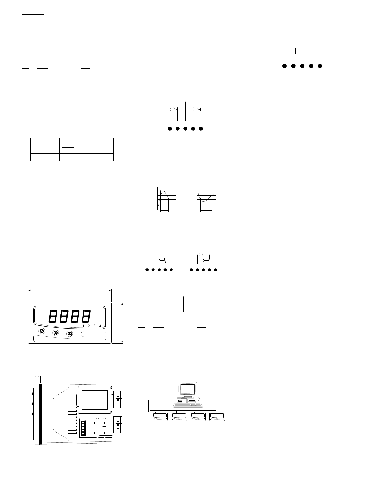
3.5.2 Current Measurement of an Externally Powered Loop
3.5.3 Voltage Connection
4.0 PROGRAMMING THE INSTRUMENT
The unit is a microprocessor based instrument enabling it to satisfy a variety of applications.
All programming is available from the front panel or via a PC using the RS485 Modbus
communications pod.
4.1 Programming Guide
The unit has three operating modes. These are :-
RUN (DISPLAYS PROCESS VARIABLE)
MENU
EDIT
RUN is the principal mode of operation, which displays the Process Variable from which all
other modes are accessed. The unit will always time-out back to this mode after one minute.
MENU mode provides access to the programmable parameters.
EDIT mode is entered from Menu Mode and allows the user to inspect and modify a
parameter.
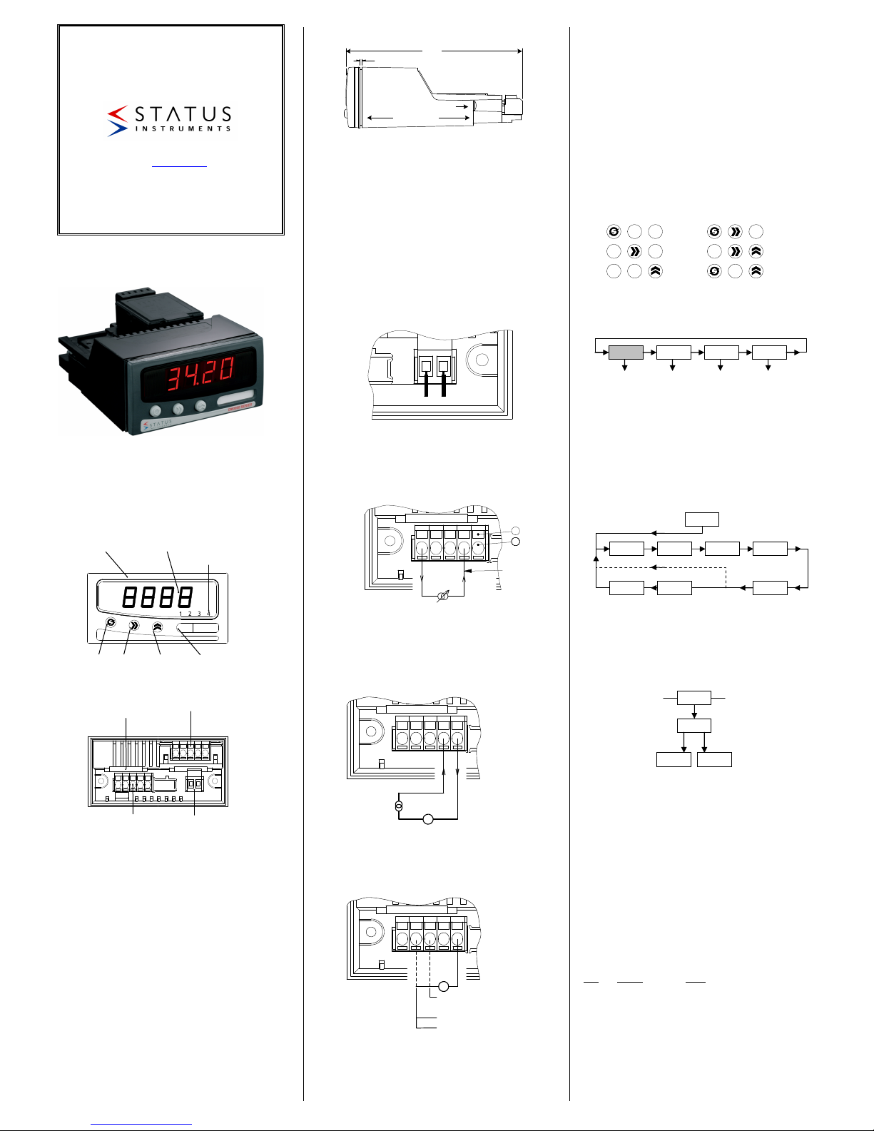
4.2 Key Definitions
All programming is done using the three front panel keys, A, B and C are shown to assist the
tutorial.
CYCLE (A), SHIFT (B) and INC (C) keys are pressed singularly.
ESCAPE (A&B), ENTER (B&C) and CLEAR (A&C) are obtained by simultaneously pressing
the two keys.
4.3 Entering Menu Mode (START PROGRAMMING)
The Root Menu mode is accessed from "Run" by pressing ENTER (B&C) followed by CYCLE
(A). The display will now show "inPt". In order to understand what this means, the following
diagram shows where we are within the basic Root menu.
*Slot menus only appear when respective option pods are fitted.
4.3.1 Moving Around The Menu
You can browse through the Root menu by pressing CYCLE (A) which moves the menu
position from left to right (after reaching SYS, the menu position wraps around to the start).
4.3.2 Entering A Submenu
To enter a submenu, first cycle around the Root menu until the required submenu is displayed.
For the purposes of this tutorial press the CYCLE (A) key until “InPt” is displayed. Pressing
SHIFT (B) enters the Input Submenu. “tYPe” will now be displayed. The diagram shows our
position in relation to other items in the menu. Pressing CYCLE (A) moves left to right,
wrapping around at the end. The unit alters items in the menu list depending upon settings
made.
4.3.3 Editing A Parameter
The items displayed in the menu can either be submenus, parameters or numbers, most of the
items in the Inputs menu are parameters which can be edited.
Press the CYCLE (A) key until “tYPe” is displayed, then press SHIFT (B).
The current setting will now be shown flashing. This item is changed by pressing the INC (C)
key.
The choice of options available is as follows:
Press the INC (C) key until "crnt" is displayed.
Note that whilst the display is flashing, the option on the display has not been saved to
memory. To select an option, the ENTER key sequence is used. Press ENTER (B&C). The
display will stop flashing momentarily before returning to Menu mode. The system
automatically steps on to the next entry to speed the process of programming. This method of
editing parameters is repeated throughout the menu structure.
4.3.4 Returning From Submenus
To return up from the inPt menu to the root menu wait for 1 minute or press the ESCAPE
(A&B) key.
Pressing the ESCAPE key from our current position in the Inputs submenu takes us back to
the Root menu. The menu position will automatically step to the next menu item, if no pods
are fitted the unit will show SYS, if pods are fitted SLt1 or SLt2 will be shown.
The Root menu, as its name suggests is not a submenu. Pressing the ESCAPE (A&B) key
sequence whilst in the Root menu will take the user out of Menu mode and into Run mode.
Thus the process variable will be shown on the display. Refer to section 5.2 if an error code is
shown after programming in menu mode.
4.4 The Menus
4.4.1 The INPt (INPUT) Submenu
The INPt submenu is used to program all the characteristics of the input sensor and any signal
conditioning that may be required. The selection of an option in the list may affect items further
down. Therefore, during programming, the user should start at the top of the menu and work
down, to avoid setting an option which may later become obsolete. Short menu only items
shown in bold.
TITLE OPTIONS DETAIL
tYPE crnt, VoLt Set Current or Voltage
dP 888.8, 88.88, 8.888, 8888 Defines decimal point location
rngE 4-20, 0-20, 0-10 mA range setting, only for Current input
rngE 1-5, 0-1, 0-10 Voltage setting, only for Voltage input
Lo 000.0 Low engineering range, -999 to 9999
Hi 100.0 High engineering range, -999 to 9999
Lin nonE, Sqrt, cust Linearity: none, square root or custom *1
FiLt nonE, 2.5 s, Input filtering or smoothing
10 s, Adaptive
uSEr in 0..... in 9 out 0......out 9
DM3420
INTELLIGENT
PROCESS INDICATOR
Designed, manufactured and supported by:
Green Lane, Business Park, Green Lane
Tewkesbury Glos. G20 8DE. UK
Tel: +44 (0)1684 296818 Fax: +44 (0)1684 293746
Every effort has been taken to ensure the accuracy of this specification, however
we do not accept responsibility for damage, injury, loss or expense resulting from
errors and omissions, and we reserve the right of amendment without notice
Stock code: 52-314-2246-02
oC
2 3 41
Tag No.
FRONT PANEL
SEALED TO IP65
BRIGHT FOUR
DIGIT DISPLAY
DISCRETE LED
ALARM INDICATORS
CYCLE
KEY
SHIFT
KEY
INCREMENT
KEY
LEGEND
WINDOW
OPTION POD SLOT 2
(NOT SHOWN)
OPTION POD SLOT 1
PROCESS
INPUT
POWER
CONNECTION
(+) L N (-)
1
2
Current
Return
Tx
(4 to 20) mA
(0 to 20) mA
(0 to 10) mA
24 V
CYCLE
SHIFT
INC
ESCAPE
ENTER
CLEAR
B
C
AB
B C
AC
A