LYSON W4075 User manual

1
MANUAL
WAX MELTER
Przedsiębiorstwo Pszczelarskie Tomasz Łysoń
Spółka z o.o. Spółka Komandytowa
34-125 Sułkowice, ul. Racławicka 162, Polska
tel. 33/875-99-40, 33/870-64-02
Siedziba Firmy Klecza Dolna 148, 34-124 Klecza Górna
2016

The following manual encompasses the devices Bering the following codes:
W4075, W4076, W4076O, W4072
Manual
1. General safety principles for wax extractors with gas burner
1.1. Usage safety
2. Work with a gas burner
2.1. Burner assembly
2.2. connecting a cylinder to a burner
2.3. Device activation
2.4. device deactivation
3. Periodical inspections
4. Operation description of the wax extractor with gas burner
5. Characteristics for wax extractors with gas burners
5.1. Wax extractor - small
5.1.1. Device diagram
5.2. Wax extractor - big
5.2.1. Device diagram
5.2.2. Placing the frames in the basket at selected arrangement
5.3. Big wax extractor - insulated
5.3.1. Device diagram
5.4. Big wax extractor –100 Dadant frames
5.4.1. Device diagram
6. Cleaning and maintenance
7. Recycling
8. Guarantee

STAINLESS STEEL WAX MELTER WITH GAS
BURNER (PROPANE-BUTANE)
General safety principles for wax extractors with
gas burners
Prior to operating the device please refer to the manual and act
according to the guidelines contained therein. The manufacturer
cannot be held accountable for the damages cause by misusing
the device or its improper handling
1. Usage safety
2. The following equipment is not intended to be used by
persons with limited physical, sensory or mental capabilities
(including children) or persons inexperienced or unfamiliar with
that type of equipment unless the usage occurs under
supervision or in line with the equipment operating manual
provided by safety supervising persons. One must make sure
that children do not play with the wax extractor
3. In case of any damage to the wax extractor, in order to
avoid the danger, the repairs may be performed solely by a
specialist servicing centre or a qualified person
4. It is forbidden to perform any maintenance works when
the device is in operation .
5. In case of any danger, the gas cylinder must be
disconnected immediately and the operators must stay away
from the device. Wax extractor will be restarted once the danger
has been eliminated.
In case when the following warning has been
ignored and the installation has been performed by a
person devoid of the relevant qualifications, there is a
risk of damage to the property, fire, explosion,
suffocation or sustaining bodily injuries that might
result in permanent disability!
•Once the device installation has been terminated
the tightness of all connections must be checked with a
tightness tester ( electronic or in the form of soapsuds)
Under no circumstances must fire be used to test the
tightness!
2. WORK WITH A GAS BURNER
2.1. BURNER ASSEMBLING
1. Legs
2. Screws to fix the legs
3. Washers to the screws fixing the legs
4. Gasket to fix the legs
5. Thermoelectric cable
6. Valve with thermoelectric protection
7. Valve hand wheel
8. Piezoelectric lighter
9. Piezoelectric lighter button
10. Lighting electrode
11. Hose tie to regulate the air flow
12. Screw to tighten the tie from point 11
13. Connector
14. Nut to control the valve
15. Support to fix the lighter and the thermoelectric
cable
16. Screw to fix the lighting electrode and
thermoelectric cable
17. Nuts to fix the lighting electrode and thermoelectric
cable
18. Cast-iron burner
19. Support to fix the piezoelectric lighter
20. Inspection connector
2.2. CONNECTING THE CYLINDER TO THE BURNER
(A). Gas cylinder shall be placed vertically at the distance
at least 1.5 meter from the device.
(B). Certified gas hose for propane-butane (item 3) shall

4
be placed on the connector (item 1) as well as on gas
reducing connector.
(C). One must check precisely whether the fixed hose has
the proper diameter.
(D). Make sure that the hose has been fixed tightly.
(E). Subsequently, the hose ties (item 2) must be placed
in order to fix the hose to the connector and gas reducing
connector, next they must be tighten with a screw-driver
or a wrench.
(F). Having completed the installation, the tightness test
must be performed with soapsuds or an electronic gas
tester.
Assembly mode for propane-butane gas regulator
Due to a high power of the device, all operations with a
valve, e.g. decreasing, increasing, cutting off the gas flow,
shall be performed slowly. Otherwise, there exists the
threat of the flame getting back to the nozzle. If such a
situation occurs, the gas flow must be closed immediately
and the burner must be reignited after approximately 2
minutes.
2.3. DEVICE ACTIVATION after the burner has been
properly connected with the cylinder, the following
activities must be performed:
Press the valve hand wheel , turn slowly anticlockwise by
approximately ¼ turn (item 2) . Ignite the gas with the
piezoelectric lighter by pressing the lighter button (item3)
Holding the valve hand wheel as pressed.After ignition,
wait 30 seconds until the thermoelectric cable starts to
operate, release the hand wheel and regulate the flame
for intended size.
2.4. DEVICE DEACTIVATION After operation has
terminated, turn the valve into position „●” –see the
figure below
PROPANE-BUTANE
1. Connector fi 100 mm
2.Hose ties
3. Certified gas hose for propane-butane
4. Connector to check the pressure
Maximum
flame
Minimum flame
(item.1 and 2 ) valve
hand wheel
(item.3)
Lighter button

5
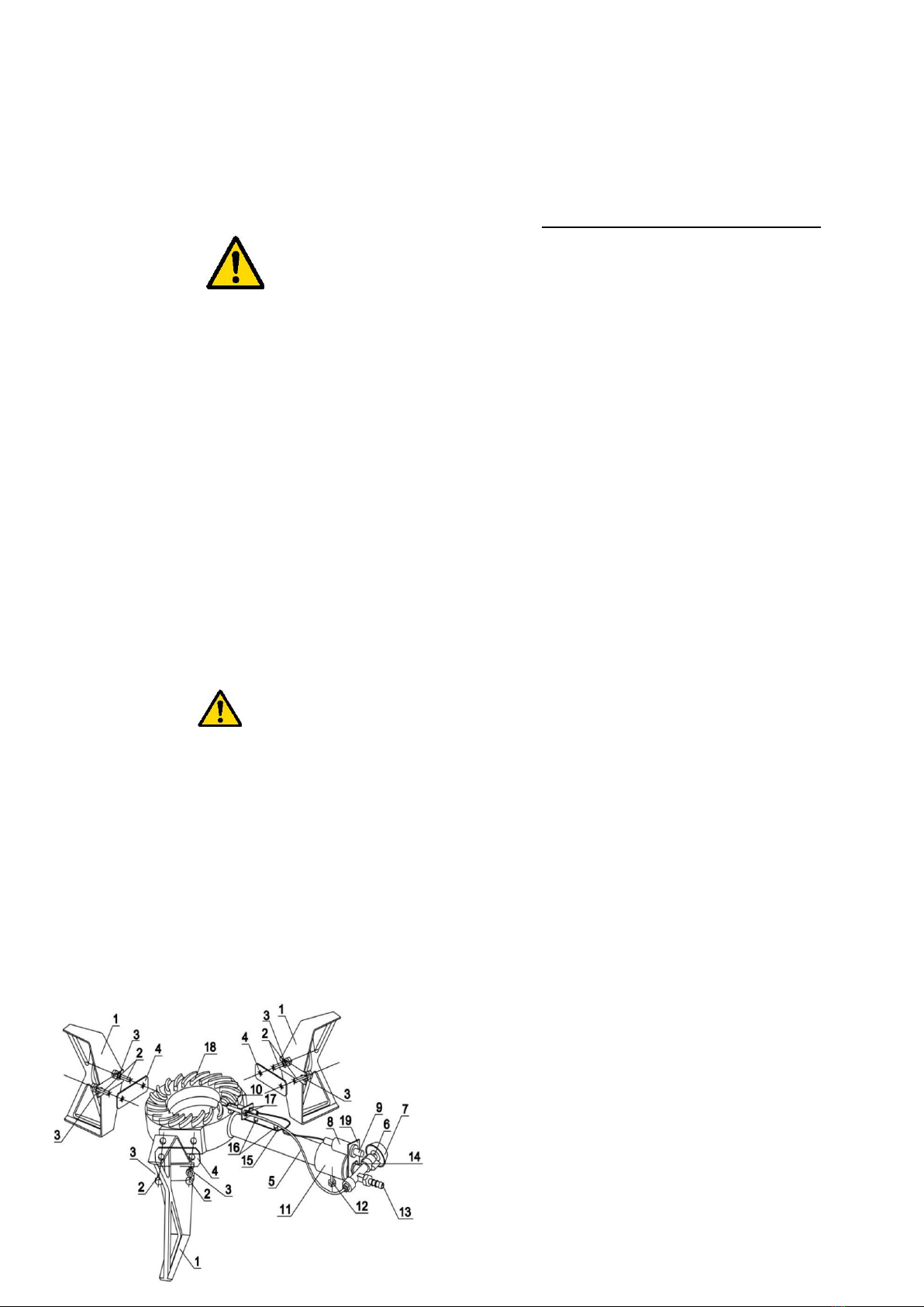
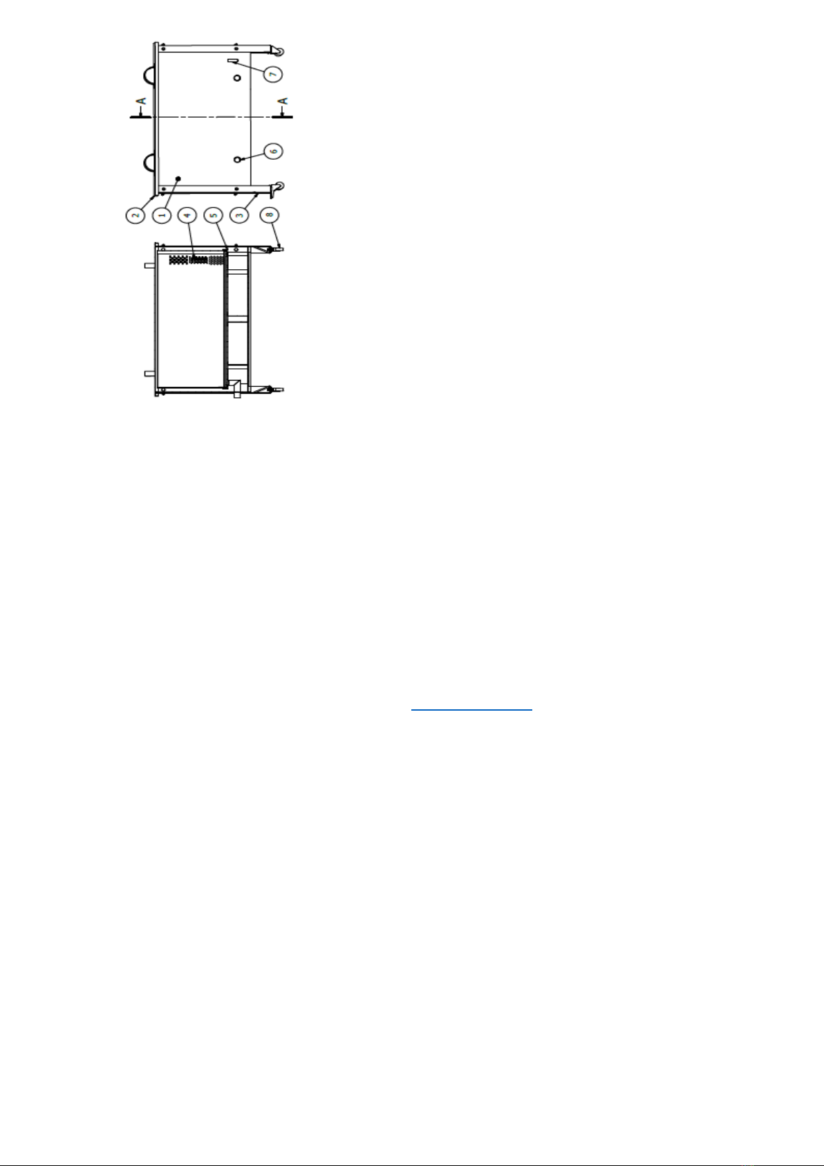
1. Slightly release the lock screw (item 1).
2. Slightly move the tie (item 2) and set up the primary air
flow in such a way to achieve blue flame optimally (yellow
or red flame indicates wrong settings)
3. Slightly tighten the lock screw (item 1) .
4. After every gas cylinder replacement, the primary air
flow must be regulated again.
Properly performed regulation should provide:
quick and proper burner ignition, re-ignition and mild
flame transfer, non-explosion flame dispersion at all flame
orifices within 5 second at the utmost, slight flame lit-off is
permissible, however after 1 minute the flame should be
stable, non-extinguishing and not getting back into the
nozzle when the thermal power of the burner is changed
along the entire range of anticipated power regulation and
while the hand wheel of the gas cock is turned from
maximum to minimum position with normal speed (the
normal speed , i.e. turning the gas cock hand wheel from
maximum to minimum power lasting approximately 1 s)
WARNING! After each usage the device must always be
cleaned. Prior to cleaning, one must make sure that gas
stool has cooled down - high risk of scalding. Gas flow
must be closed by closing the cocks. In case when the
device is to be rotated during cleaning, it is necessary to
disconnect the gas supplying hose.
(A). Prior to starting the maintenance, device must be
switched off and gas supplying hose disconnected.
(B). Make sure that the device has cooled down.
(C). In order to prevent the damages to the device
surface, it must be cleaned regularly.
(D). Remains of fat or food inside the device may bring
about fire.
(E). The device is to be cleaned with a wet cloth.
(F). Use the neutral cleaning agents only. Never use the
abrasive agents, agents containing caustic substances,
bleaches or acids to clean the gas stool. Using acidic or
alkaline substances must be avoided ( lemon juice,
vinegar, etc) .
(G). Do not clean the device with steam washers.
(H). Once the device has been cleaned, it must be dried.
3. PERIODICAL INSPECTIONS
After the guarantee period has expired, the device must
be inspected at least once a year. Periodical inspections
must be performed by the persons qualified for repairs
and maintenance of gas devices. The minimum inspection
range shall include the control for proper operation, gas
valve maintenance and the tightness tests. Outside the
guarantee period periodical inspections are not included
into the costs of purchasing the device.
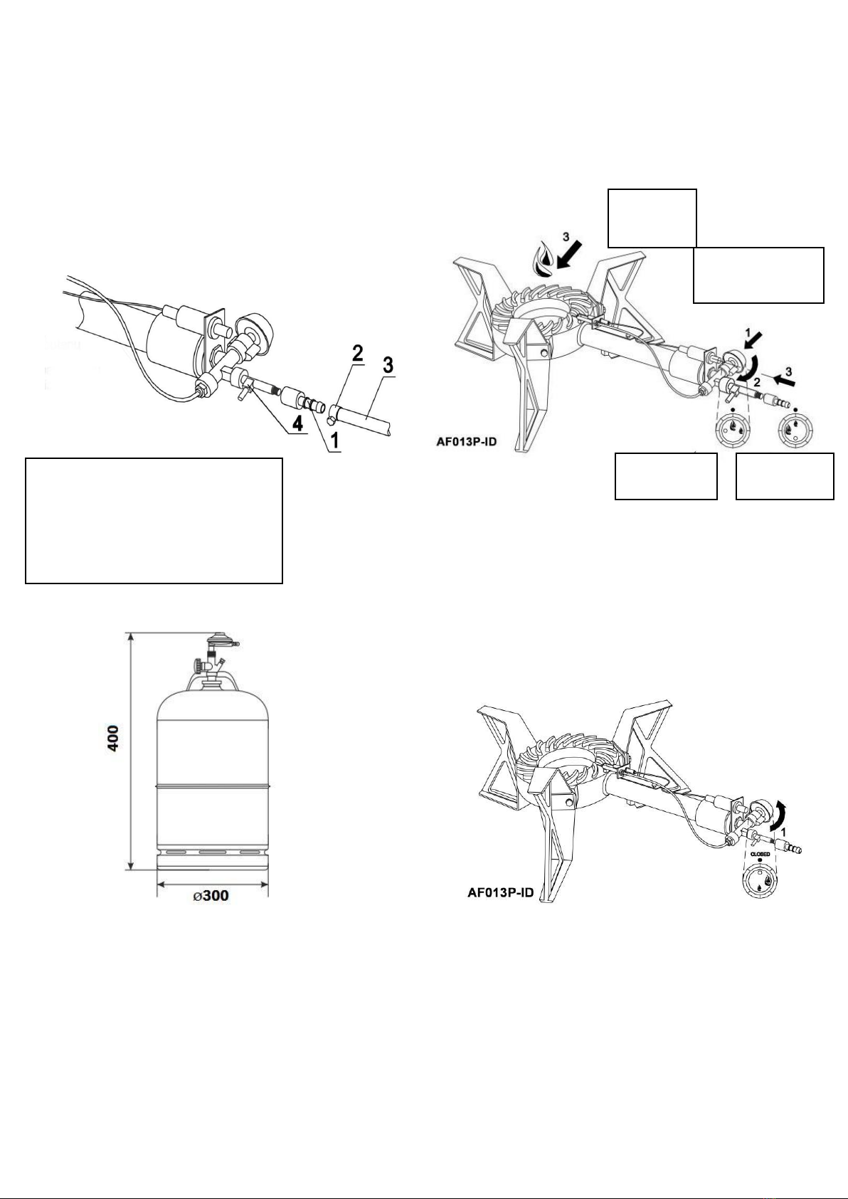
Properly prepared burner with the regulator to be
connected to the gas cylinder.
4. OPERATION DESCRIPTION OF A WAX
EXTRACTOR WITH A GAS BURNER
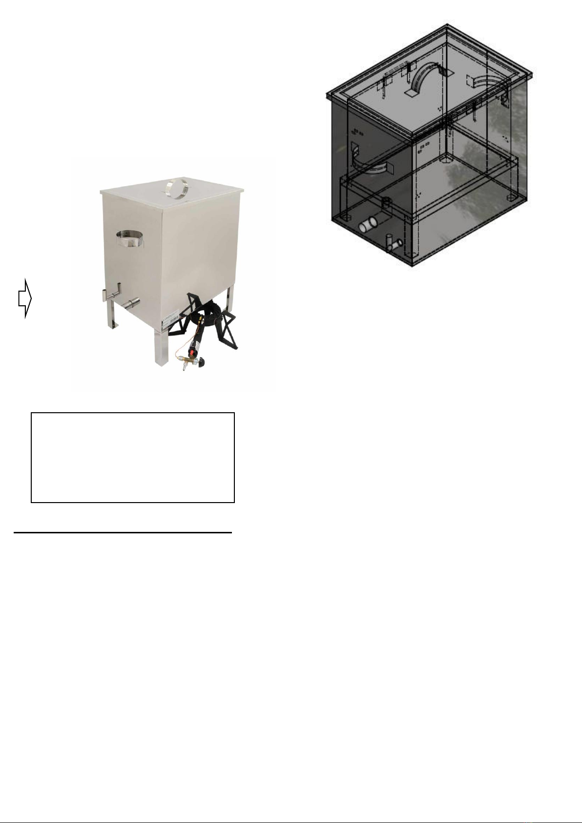
1. Fill the tank with water until the level of the
discharge pipe, as in the figure (Fig. 1). Water losses
must be completed (take special precautions not to get
burnt).
2. Fill the basket with frames or dried honey. .
3. Cover the device with a lid.
4. Place the burner under the device in such a way to
make the flame heat the entire surface of the device
bottom.
5. Wait until steam is formulated and melted wax
flows out.
6. After the batch has been melted, check the water
level and make up for the potential losses.
7. Add the frames or dried honey in the basket.
8. Steps 6 and 7 to be repeated until extraction has
been terminated
9. Once the process has ended, the burner must
be switched off and the gas cylinder closed.
Air flow regulation
1. lock screw
2. hose tie to regulate the air flow

6
10. Remove the marc wax from the basket and
prepare it for reuse. .
11. The following equipment is not intended to be
used by persons with limited physical, sensory or mental
capabilities (including children) or persons inexperienced
or unfamiliar with that type of equipment unless the usage
occurs under supervision or in line with the equipment
operating manual provided by safety supervising
persons.
12. Water is to be added through the inlet, see Fig no
1.
5. Characteristics of the wax extractors
Devices intended to extract wax from beehive frames or
dried honey by means of steam method. They consist of
external tank, containing water, and the basket holding the
frames or dried honey. Additional equipment includes a
gas stool, owing to which steam is formulated by heating
the water tank.
5.1. Wax extractor - small
5.2. Wax extractor - big
5.3. Wax extractor –big and insulated
5.4. Wax extractor –big –100 frames
5.1. Wax extractor - small
Device parameters:
•material–stainless steel
Tank external dimensions:
•length - 515 mm
•width - 360 mm
•height - 495 mm
External dimensions of the frame basket
•length –445 mm
•width - 290 mm
•height –330 mm
•discharge diameter - 1”
Additional equipment:
•gas stool, power 7,5KW with thermocouple
•power supply –propane-butane gas
The set does not contain the gas cylinder
regulator
Capacity for entire frames:
•7 - 10 frames –type: Wielkopolska, Ostrowska’s
•7 - 10 frames –type: Warsaw ordinary
•7 - 10 Dadant frames
•Extended Warsaw frame DOES NOT FIT INTO a
small wax extractor
Small wax extractor does not have legs, it is to be
placed on the gas stool directly!!!
Fig. 1
Water level is completed until the height of the
outlet (pipe)
When the device is operational water is to be
added.
Pour into an inspection hole with a funnel so
as not lose heat inside the extractor and avoid
being burnt with hot steam

7
5.1.1. Diagram for a small wax extractor
Legend
1. Wax extractor tank
2. Wax extractor lid
3. Frame basket
4. Basket base
5. Pipe for water level
6. Wax discharging pipe
5.2. WAX EXTRACTOR –BIG
Device parameters:
•material –stainless steel
Tank external dimensions:
•length - 580 mm
•width - 420 mm
•height - 610 mm
External dimensions of the frame basket:
•length –530 mm
•width - 335 mm
•height –440 mm
•discharge diameter - 1”
Total height of the device 820 mm
Additional equipment:
•gas stool, power 7,5Kw
•power supply –propane-butane gas
The set does not contain the gas cylinder
regulator
5.2.1. Diagram for a big wax extractor
Legend
Wax extractor tank
Wax extractor lid
Frame basket
Basket base
Water level pipe
Wax discharging pipe
Wax extractor legs
5.2.2. Placing the frames in the basket with selected
arrangement
Arrangement 1.
Frame type
The number of frames fitting
into the basket
Dadant
14 Hoffman-type frames
Extended Warsaw type
14 Hoffman-type frames
Warsaw ordinary type
14 Hoffman-type frames
Wielkopolska, Ostrowska’s
14 Hoffman-type frames

8
Arrangement 2.
Frame type
The number of frames fitting
into the basket
Dadant
14 Hoffman-type frames
Extended Warsaw type
14 Hoffman-type frames
Warsaw ordinary type
14 Hoffman-type frames
Wielkopolska, Ostrowska’s
14 Hoffman-type frames
Arrangement 3.
Frame type
The number of frames fitting
into the basket
Wielkopolska, Ostrowska’s
20 Hoffman-type frames
Arrangement 4.
Frame type
The number of frames fitting
into the basket
Dadant
12 Hoffman-type frames
Extended Warsaw type
12 Hoffman-type frames
Warsaw ordinary type
12 Hoffman-type frames
Wielkopolska, Ostrowska’s
12 Hoffman-type frames
5.3.Wax extractor –big and insulated
The sides of the device are thermally insulated with
mineral wool, which increases the device’s operational
efficiency.
Device parameters:
•material –stainless steel
External dimensions of the tank:
•length - 585 mm
•width - 520 mm
•height - 620 mm
Dimensions of the frame basket:
•length –440 mm
•width - 380 mm
•height –435 mm
•discharge diameter - 1”
External dimensions
•length - 520 mm
•width - 455mm

9
•height - 610 mm
Depending on the frame types, the wax extractor
can hold between 10 and 2- frames
Additional equipment:
•gas stool, power 7,5Kw
•power supply –propane-butane gas
•
The set does not include the gas cylinder
regulator
5.3.1.Diagram for wax extractor –big , insulated
Legend:
Wax extractor tank
Wax extractor lid
Frame basket
Basket base
Water level pipe
Wax discharging pipe
Wax extractor legs
Wax extractor insulation
5.4.1. Diagram for wax extractor –big, 100 Dadant
frames
The device is intended to extract wax from the beehive
frames or dried honey by means of a steam method. It is
recommended for big apiaries.
.
Device parameters :
•material –stainless steel
•power supply –propane-butane gas
•discharge diameter –40 mm –2 pcs
•water inlet diameter- 25 mm
Water tank dimensions:
•tank external height 830 mm
•tank external width 1154x1154 mm
Dimensions of the frame basket:
•height 430 mm
•width 990 x 990 mm
Additional equipment –at extra charge :
•second gas stool
•wheels
Included in the set –one gas stool for free!
5.4.2. Diagram for wax extractor –100 Dadant
frames

10
Legend:
1. Wax extractor tank
2. Wax extractor lid
3. Wax extractor legs
4. Frame basket
5. Basket base
6. Was discharging pipe
7. Water level pipe
8. Wheels
Additional options for wax extractors
•Sealing ring –prevents from steam losses
•Furnace made of furnace steel
6. Cleaning and maintenance
Prior to every season, an additional inspection must be
performed for technical issues and in case any fault has
been detected, a service point must be contacted
Wax extractor must be cleaned thoroughly after use
with hot water containing slight quantities of agents
permitted to be used for cleaning the devices coming in
contact with food, or by means of a pressure washer.
7.Recycling
Worn-out product must be removed as waste only within
selective waste collection organised by the Network of
Communal Electric and Electronic Waste Collecting
Points. A customer is entitled to return the used
equipment to the electrical equipment distributor network,
at least free of charge and directly, if the device to be
returned is of proper type and serves the same purpose
as the newly purchased device
8.Warranty
Product purchased from “Łysoń’ company are
encompassed by the manufacturer’s guarantee.
The guarantee duration equals 24 months.
A receipt or a VAT invoice is issued for each product
purchased.
Detailed guarantee terms and conditions, see
www.lyson.com.pl

11
INSTRUKCJA OBSŁUGI
URZĄDZENIA DO WYTOPU WOSKU
Przedsiębiorstwo Pszczelarskie Tomasz Łysoń
Spółka z o.o. Spółka Komandytowa
34-125 Sułkowice, ul. Racławicka 162, Polska
www.lyson.com.pl, email; lyson@lyson.com.pl
tel. 33/875-99-40, 33/870-64-02
Siedziba Firmy Klecza Dolna 148, 34-124 Klecza Górna


1
Instrukcja obejmuje urządzenia o kodach:
W4075, W4076, W4076O, W4072
Instrukcja obsługi
1. Ogólne zasady bezpieczeństwa urządzeń do
wytopu wosku z palnikiem gazowym
1.1. Bezpieczeństwo użytkowania
2. Praca z palnikiem gazowym
2.1. Złożenie palnika
2.2. Podłączenie butli do palnika
2.3. Włączanie urządzenia
2.4. Wyłączanie urządzenia
3. Przeglądy okresowe
4. Opis działania urządzenia do wytopu wosku z
palnikiem gazowym
5. Charakterystyka urządzeń do wytopu wosku
z palnikiem gazowym
5.1. Urządzenie do wytopu wosku małe
5.1.1. Schemat urządzenia
5.2. Urządzenie do wytopu wosku duże
5.2.1. Schemat urządzenia
5.2.2. Ułożenie ramek w koszu przy wybranym
układzie
5.3. Urządzenie do wytopu wosku duże - ocieplone
5.3.1. Schemat urządzenia
5.4. Urządzenie do wytopu wosku duże – 100 ramek
Dadant
5.4.1. Schemat urządzenia
6. Czyszczenie i konserwacja
7. Utylizacja
8. Gwarancja

2
TOPIARKI NIERDZEWNE Z PALNIKIEM
GAZOWYM (PROPAN-BUTAN)
1.Ogólne zasady bezpieczeństwa urządzeń do
wytopu wosku z palnikiem gazowym
Przed rozpoczęciem użytkowania urządzenia należy
przeczytać instrukcję użytkowania i postępować według
wskazówek w niej zawartych. Producent nie odpowiada
za szkody spowodowane użytkowaniem urządzenia
niezgodnie z jego przeznaczeniem lub niewłaściwą jego
obsługą.
1.Bezpieczeństwo użytkowania
1. Niniejszy sprzęt nie jest przeznaczony do użytkowania
przez osoby (w tym dzieci) o ograniczonej zdolności
fizycznej, czuciowej lub psychicznej lub osoby nie mające
doświadczenia lub znajomości sprzętu, chyba, że odbywa
się to pod nadzorem lub zgodnie z instrukcją użytkowania
sprzętu, przekazanej przez osoby odpowiadające za ich
bezpieczeństwo. Należy zwracać uwagę na dzieci, aby
nie bawiły się topiarką.
2. W przypadku uszkodzenia topiarki, w celu uniknięcia
zagrożenia, naprawę może przeprowadzić tylko
specjalistyczny zakład naprawczy albo wykwalifikowana
osoba.
3. Zabrania się prowadzić jakichkolwiek prac
konserwacyjnych podczas używania urządzenia.
4. W przypadku jakiegokolwiek zagrożenia należy
bezzwłocznie odłączyć butlę z gazę i odsunąć się od
urządzenia. Ponowne uruchomienie topiarki może
nastąpić po wyeliminowaniu zagrożenia.
W przypadku zignorowania niniejszego
ostrzeżenia i wykonania instalacji przez osobę bez
odpowiednich kwalifikacji, istnieje zagrożenie
uszkodzenia urządzenia, uszkodzenia mienia,
pożaru, eksplozji, uduszenia lub odniesienia innych
obrażeń mogących skutkować trwałym kalectwem!
•Po zakończeniu instalacji urządzenia należy
sprawdzić szczelność wszystkich połączeń
stosując tester szczelności (elektroniczny lub w
postaci mydlin).
Do sprawdzania szczelności nie wolno w żadnym
wypadku stosować ognia!
2. PRACA Z PALNIKIEM GAZOWYM
2.1. ZŁOŻENIE PALNIKA
1. Nogi
2. Śruby mocujące nogi
3. Podkładki do śrub mocujących nogi
4. Uszczelka do mocowania nóg
5. Przewód termoelektryczny
6. Zawór z zabezpieczeniem termoelektrycznym
7. Pokrętło zaworu
8. Zapalacz piezoelektryczny
9. Przycisk zapalacza piezoelektrycznego
10.Elektroda zapalająca
11.Opaska regulująca dopływ powietrza
12.Śruba do dokręcania opaski z pkt. 11
13.Króciec podłączeniowy
14.Nakrętka kontrolująca zawór
15.Wspornik mocujący zapalacz i przewód
termoelektryczny
16.Śruby mocujące elektrodę zapalającą i przewód
termoelektryczny
17.Nakrętki mocujące elektrodę zapalającą i
przewód termoelektryczny
18.Palnik żeliwny
19.Wspornik mocujący zapalacz piezoelektryczny
20.Króciec do sprawdzenia
2.2. PODŁĄCZANIE BUTLI DO PALNIKA
(A). Butla gazowa powinna zostać ustawiona pionowo w
odległości, co najmniej 1,5 metra od urządzenia.

3
(B). Atestowany wąż gazowy do gazu propan-butan (poz.
3) należy nałożyć na króciec podłączeniowy (poz. 1) oraz
na króciec reduktora gazowego.
(C). Należy dokładnie sprawdzić czy posiadany wąż jest
odpowiedniej średnicy.
(D). Upewnij się, że wąż jest umocowany bardzo ciasno.
(E). Następnie należy nałożyć opaski zaciskowe (poz. 2)
w celu umocowania węża do króćca podłączeniowego i
króćca reduktora gazowego, i dokręcić je wkrętakiem lub
kluczem.
(F). Po wykonanej instalacji należy wykonać test
szczelności przy użyciu roztworu wody z mydłem lub
elektronicznego testera gazowego.
Sposób montażu reduktora do gazu propan-butan
Ze względu na wysoką moc urządzenia wszelkie
operacje zaworem, m. in. zmniejszanie, zwiększanie,
zamykanie dopływu gazu należy przeprowadzać powoli.
W przeciwnym wypadku grozi to cofnięciem płomienia na
dyszę. Jeżeli nastąpi taka sytuacja należy natychmiast
zamknąć dopływ gazu i po około 2 minutach uruchomić
ponownie palnik.
2.3. WŁĄCZANIE URZĄDZENIA po poprawnym
podłączeniu palnika do butli należy wykonać następujące
czynności:
Wciśnij pokrętło zaworu, powoli przekręć w kierunku
przeciwnym do ruchu wskazówek
zegara o około ¼ obrotu (poz. 2). Zapal gaz zapalaczem
piezoelektrycznym wciskając przycisk zapalacza (poz. 3)
trzymając wciśnięte pokrętło zaworu. Po zapaleniu
odczekaj 30 sekund, aby przewód termoelektryczny
zaczął działać, następnie puść pokrętło i wyreguluj
płomień do żądanej wielkości.
2.4. WYŁĄCZANIE URZĄDZENIA Po zakończeniu
użytkowania urządzenia przekręć zawór w pozycję „●” –
patrz rysunek poniżej
PROPN BUTAN
1. Króciec podłączeniowy fi 100 mm
2.Opaski zaciskowe
3. Atestowany wąż gazowy do propan-butan
4. Króciec do sprawdzania ciśnienia

4
1. Odkręć lekko śrubę kontrującą (poz. 1).
2. Powoli przesuń opaskę (poz. 2) i ustaw dopływ
powietrza pierwotnego, w taki sposób, aby uzyskać,
optymalnie niebieski płomień ( żółty lub czerwony
wskazuje na złe ustawienie).
3. Powoli dokręć śrubę kontrującą (poz. 1).
4. Po każdorazowej wymianie butli gazowej należy
ponownie wykonać regulację dopływu powietrza
pierwotnego.
Prawidłowo przeprowadzona regulacja powinna
zapewnić:
szybki i prawidłowy zapłon palnika, ponowny zapłon oraz
przenoszenie płomienia łagodne, bez wybuchowe
rozprzestrzenianie się płomienia na wszystkich otworach
płomykowych w czasie nie dłuższym niż 5 sekund,
niewielkie odrywanie się płomienia jest dopuszczalne,
aczkolwiek po upływie 1 minuty płomień powinien być
stabilny,
nie gasnący i nie cofający się na dyszę płomień przy
zmianie mocy cieplnej palnika w całym zakresie
przewidzianej regulacji mocy i przy obracaniu pokrętła
kurka z położenia mocy maksymalnej do minimalnej z
normalną szybkością (normalna szybkość tzn. obrócenia
pokrętła kurka od położenia mocy maksymalnej do
minimalnej trwające ok. 1s).
OSTRZEŻENIE! Po użyciu należy zawsze wyczyścić
urządzenie Przed przystąpieniem do czyszczenia, należy
upewnić się, że taboret wystygł - istnieje wysokie ryzyko
oparzenia. Należy zamknąć dopływ gazu do urządzenia
przez zakręcenie kurków. W przypadku, gdy w trakcie
czyszczenia zamierzamy obracać urządzenie, konieczne
jest odłączenie węża doprowadzającego gaz do
urządzenia.
(A). Przed przystąpieniem do konserwacji należy
wyłączyć urządzenie i odłączyć węża z zasilaniem
gazowym.
(B). Upewnić się, że urządzenie ostygło.
(C). Aby zapobiec uszkodzeniu powierzchni urządzenia,
należy regularnie ją czyścić.
(D). Pozostałości tłuszczu lub potraw w urządzeniu mogą
stać się przyczyną pożaru.
(E). Czyścić urządzenie za pomocą wilgotnej szmatki.
(F). Stosować wyłącznie neutralne środki czyszczące. Do
czyszczenia taboretu nigdy nie należy używać środków
ściernych, środków zawierających substancje żrące,
wybielające lub kwasy, należy również unikać stosowania
substancji kwaśnych lub alkalicznych (sok z cytryny, ocet
itp.).
(G). Nie czyścić urządzenia za pomocą myjek parowych.
(H). Po wyczyszczeniu, urządzenie należy wysuszyć.
3. PRZEGLĄDY OKRESOWE
Po upływie okresu gwarancji przynajmniej raz w roku
urządzenie powinno być poddane przeglądowi
okresowemu.
Przeglądy okresowe powinny być dokonywane przez
osoby posiadające kwalifikacje w zakresie naprawy i
konserwacji urządzeń gazowych.
Minimalny zakres przeglądu okresowego to kontrola
prawidłowego działania, konserwacja zaworów
gazowych oraz próba szczelności gazowej urządzenia.
Przeglądy okresowe po upływie okresu gwarancji nie są
wliczone w koszty zakupu urządzenia.
Prawidłowo przygotowany palnik z reduktorem do
podpięcia
do butli.

5
4. OPIS DZIAŁANIA URZĄDZENIA DO WYTOPU
WOSKU Z PALNIKIEM GAZOWYM
1. Zalać zbiornik wodą do poziomu rurki spustowej jak
na zdjęciu (Fot.1). Ubytek wody uzupełniać
(zachować szczególną ostrożność aby się nie
poparzyć).
2. Napełnić kosz ramkami lub suszem.
3. Urządzenie przykryć pokrywą.
4. Palnik umieścić pod urządzeniem w taki sposób aby
płomień nagrzewał całą powierzchnię dna
urządzenia.
5. Poczekać do wytworzenia się pary wodnej i
wypłynięcia wytopionego wosku.
6. Po wytopieniu wsadu sprawdzić poziom wody a
ewentualny brak uzupełnić.
7. Uzupełnić kosz ramkami lub suszem.
8. Czynności 6 i 7 powtarzać do zakończenia wytopu.
9. Po zakończeniu procesu wyłączyć palnik i
zakręcić butlę z gazem.
10. Wyczyścić kosz ze znajdujących się w nim zboin i
przygotować do kolejnego użycia.
11. Niniejszy sprzęt nie jest przeznaczony do
użytkowania przez osoby (w tym dzieci) o
ograniczonej zdolności fizycznej, czuciowej lub
psychicznej lub osoby nie mające doświadczenia lub
znajomości sprzętu, chyba, że odbywa się to pod
nadzorem lub zgodnie z instrukcją użytkowania
sprzętu, przekazanej przez osoby odpowiadające za
ich bezpieczeństwo.
12. Wodę uzupełniamy przez wlot jak na Fot. nr1
5. Charakterystyka urządzeń do wytopu wosku
Urządzenia to przeznaczone są do odzyskiwania wosku
z ramek pszczelich lub samego suszu metodą parową.
Składają się one ze zbiornika zewnętrznego, w którym
znajduje się woda oraz z kosza mieszczącego ramki lub
susz. Wyposażeniem dodatkowym jest taboret gazowy,
dzięki któremu podgrzewając zbiornik z wodą
uzyskujemy parę wodna.
5.1. Urządzenie do wytopu wosku małe
5.2. Urządzenie do wytopu wosku duże
5.3. Urządzenie do wytopu wosku duże ocieplone
5.4. Urządzenie do wytopu wosku duże – 100 ramek
5.1. Urządzenie do wytopu wosku małe
Fot.1.
Poziom wody uzupełniamy do wysokości wylotu (rurka )
Wodę podczas pracy urządzenia uzupełniamy.
Za pomocą lejka wlewamy przez otwór kontrolny
aby nie tracić ciepła wewnątrz topiarki
oraz uniknąć poparzenia gorącą parą.

6
Parametry urządzenia:
•materiał – stal nierdzewna
Wymiary zewnętrzne zbiornika:
•długość - 515 mm
•szerokość - 360 mm
•wysokość - 495 mm
Wymiary zewnętrzne kosza na ramki:
•długość – 445 mm
•szerokość - 290 mm
•wysokość – 330 mm
•średnica spustu - 1”
Wyposażenie dodatkowe:
•taboret gazowy moc 6,4Kw z termoparą
•zasilanie –gaz propan-butan
Zestaw nie zawiera reduktora do butli
Pojemność całych ramek:
•7 - 10 ramek Wielkopolskich, Ostrowskiej
•7 - 10 ramek Warszawskich Zwykłych
•7 - 10 ramek Dadant
•ramka Warszawska Poszerzana NIE MIEŚCI SIĘ
w topiarce gazowej małej
Topiarka parowa mała nie posiada nóg, umieszcza
się ją bezpośrednio na taborecie gazowym!!!
5.1.1. Schemat małego urządzenia do wytopu wosku
Legenda
1. Zbiornik topiarki
2. Pokrywa topiarki
3. Kosz na ramki
4. Podstawa kosza
5. Rurka poziomu wody
6. Rurka spustowa wosku
5.2. URZĄDZENIE DO WYTOPU WOSKU DUŻE
Parametry urządzenia:
•materiał – stal nierdzewna
Wymiary zewnętrzne zbiornika:
•długość - 580 mm
•szerokość - 420 mm
•wysokość - 610 mm
Wymiary zewnętrzne kosza na ramki:
•długość – 530 mm
•szerokość - 335 mm

7
•wysokość – 440 mm
•średnica spustu - 1”
Wysokość całkowita urządzenia 820 mm
Wyposażenie dodatkowe:
•taboret gazowy moc 7,0Kw z termoparą
•zasilanie –gaz propan-butan
Zestaw nie zawiera reduktora do butli
5.2.1. Schemat dużego urządzenia do wytopu
wosku
Legenda
1. Zbiornik topiarki
2. Pokrywa topiarki
3. Kosz na ramki
4. Podstawa kosza
5. Rurka poziomu wody
6. Rurka spustowa wosku
7. Nogi miodarki
5.2.2. Ułożenie ramek w koszu przy wybranym
układzie
Układ 1.
Rodzaj ramki
Ilość ramek mieszczących
się do kosza
Dadant
14 ramek hoffmanowskich
Warszawska Poszerzana
14 ramek hoffmanowskich
Warszawska Zwykła
14 ramek hoffmanowskich
Wielkopolska, Ostrowskiej
14 ramek hoffmanowskich
Układ 2.
Rodzaj ramki
Ilość ramek mieszczących
się do koszał
Dadant
14 ramek hoffmanowskich
Warszawska Poszerzana
14 ramek hoffmanowskich
Warszawska Zwykła
14 ramek hoffmanowskich
Wielkopolska, Ostrowskiej
14 ramek hoffmanowskich

8
Układ 3.
Rodzaj ramki
Ilość ramek mieszczących
się do kosza
Wielkopolska, Ostrowskiej
20 ramek hoffmanowskich
Układ 4.
Rodzaj ramki
Ilość ramek mieszczących
się do kosza
Dadant
12 ramek hoffmanowskich
Warszawska Poszerzana
12 ramek hoffmanowskich
Warszawska Zwykła
12 ramek hoffmanowskich
Wielkopolska, Ostrowskiej
12 ramek hoffmanowskich
5.3.Urządzenie do wytopu wosku duże ocieplone
Boki urządzenie oraz pokrywa ocieplone są wełną
mineralną, co znacznie zwiększa wydajność pracy.
Parametry urządzenia:
•materiał – stal nierdzewna
Wymiary zewnętrzne zbiornika:
•długość - 585 mm
•szerokość - 520 mm
•wysokość - 620 mm
Wymiary kosza na ramki:
•długość – 440 mm
•szerokość - 380 mm
•wysokość – 435 mm
•średnica spustu - 1”
Wymiary wewnętrzne
•długość - 520 mm
•szerokość - 455mm
•wysokość - 610 mm
Topiarka w zależności od rodzaju ramek może
pomieścić od 10 do 20 ramek
Wyposażenie dodatkowe:
•taboret gazowy moc 6,4Kw z termoparą
•zasilanie –gaz propan-butan
Zestaw nie zawiera reduktora do butli
5.3.1.Schemat urządzenia do wytopu wosku –
urządzenie duże – ocieplone
This manual suits for next models
3
Table of contents
Languages:
Other LYSON Farm Equipment manuals