SteelMax Rail Runner 2 User manual


Contents
1. GENERAL INFORMATION............................................................................................... 3
1.1. Application................................................................................................................. 3
1.2. Technical data............................................................................................................ 4
1.3. Equipment included ................................................................................................... 5
1.4. Dimensions................................................................................................................ 6
1.5. Design ....................................................................................................................... 7
2. SAFETY PRECAUTIONS.................................................................................................. 8
3. STARTUP AND OPERATION..........................................................................................10
3.1. Assembling the semi-flexible or rigid track ................................................................10
3.2. Assembling the ring track..........................................................................................12
3.3. Positioning on a straight track...................................................................................14
3.4. Positioning on a curved track....................................................................................16
3.5. Preparing and connecting.........................................................................................17
3.6. Connecting to the welding circuits.............................................................................18
3.7. Operating..................................................................................................................19
3.8. Adjusting the pressure of rollers................................................................................25
3.9. Adapting for seam tracking (option)...........................................................................26
3.10. Troubleshooting ......................................................................................................30
4. MAINTENANCE...............................................................................................................31
5. ACCESSORIES...............................................................................................................32
5.1. Seam tracking attachment.........................................................................................32
5.2. Tracking sensor tips..................................................................................................32
5.3. Motorized vertical slide..............................................................................................33
5.4. 0.5 m (1.5 ft) signal cable..........................................................................................33
5.5. Semi-flexible track.....................................................................................................34
5.6. Rigid track.................................................................................................................34
5.7. Rack adjustment tool.................................................................................................34
5.8. Contact block............................................................................................................35
5.9. Magnetic units...........................................................................................................36
5.10. Semi-flexible track support......................................................................................40
5.11. Vacuum track system..............................................................................................41
5.12. Ring tracks..............................................................................................................42
5.13. Ring track supports.................................................................................................44
5.14. Torch clamps ..........................................................................................................45
5.15. Rods .......................................................................................................................46
5.16. Torch holders..........................................................................................................47
5.17. Transport attachment..............................................................................................49
5.18. Pendulum oscillator.................................................................................................49
6. WIRING DIAGRAM..........................................................................................................52
7. EXPLODED DRAWINGS AND PARTS LIST....................................................................55
8. DECLARATION OF CONFORMITY.................................................................................66
9. WARRANTY CARD..........................................................................................................67
Rail Runner 2
Rail Runner 2 –Operator’s Manual
3
1. GENERAL INFORMATION
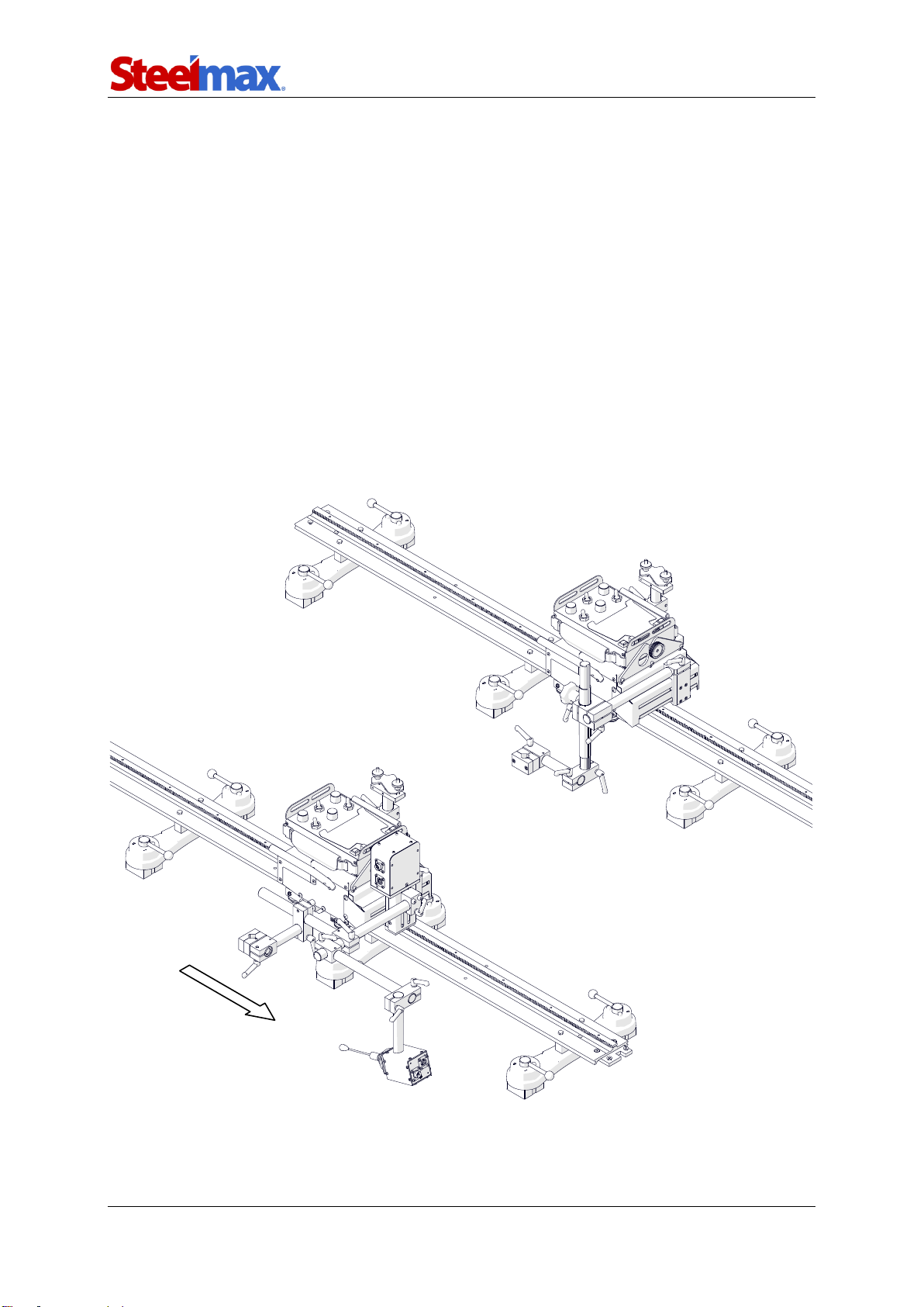
1.1. Application
The Rail Runner 2 is a track carriage designed to cut and to make butt and fillet
welds with or without oscillation. The carriage allows MIG/MAG, oxy-fuel, or plasma
torches. The track is clamped with magnetic units to ferromagnetic surfaces that are
flat or curved.
Accessories allow, for example, using torches with a larger diameter, guiding
the carriage on a semi-flexible, rigid, or ring track, and tracking the welding seam.
Using a vacuum track system allows the track to be clamped to surfaces that are
non-ferromagnetic.
Two intended configurations are shown in the figure that follows.
Basic configuration
Configuration with seam tracking in two
axes (requires an optional tracking
attachment and a motorized vertical slide)
Travel direction
Rail Runner 2
Rail Runner 2 –Operator’s Manual
4
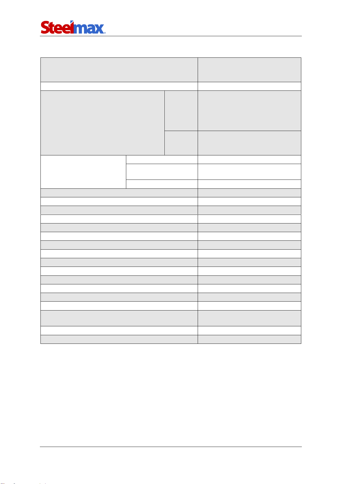
1.2. Technical data
Voltage
1~ 230 V, 50–60 Hz
1~ 115 V, 50–60 Hz
1~ 42 V, 50–60 Hz (60 V DC)
Power
120 W
Welding position
(according to EN ISO 6947 and
AWS/ASME)
Horizontal
PA / 1F / 1G
PB / 2F
PC / 2G
PD / 4F
PE / 4G
Vertical
PF / 3G
PG / 3F (contact your dealer)
PG / 3G
Outer diameter
of round workpiece
Ring tracks
200 mm (8″) – 3 m (10 ft)
Custom rolled tracks
3 m (10 ft) –10 m (32 ft)
(contact your dealer)
Semi-flexible tracks
Minimum 10 m (32 ft)
Torch type
MIG/MAG, oxy-fuel, plasma
MIG/MAG torch diameter
16–22 mm (0.63–0.87″)
Minimum workpiece thickness for magnetic clamping
5 mm (0.2″)
Horizontal pulling force
400 N (88 lbs)
Vertical pulling force
300 N (66 lbs)
Horizontal speed
0–300 cm/min (0–120 in/min)
Vertical speed
0–300 cm/min (0–120 in/min)
Oscillation type
Linear
Weld path
Straight, triangle, trapezoid, square
Oscillation width
0.2–11.8 cm (0.1–4.5″)
Oscillation speed
10–300 cm/min (5–120 in/min)
Oscillation dwell time at center and on ends
0–5 s
Maximum oscillator pulling force
100 N (22 lbs)
Allowed ambient temperature
0–45°C (32–113°F)
Maximum allowed ambient humidity without
condensation
80%
Protection level
IP 23
Weight
10 kg (22 lbs)
Rail Runner 2
Rail Runner 2 –Operator’s Manual
5
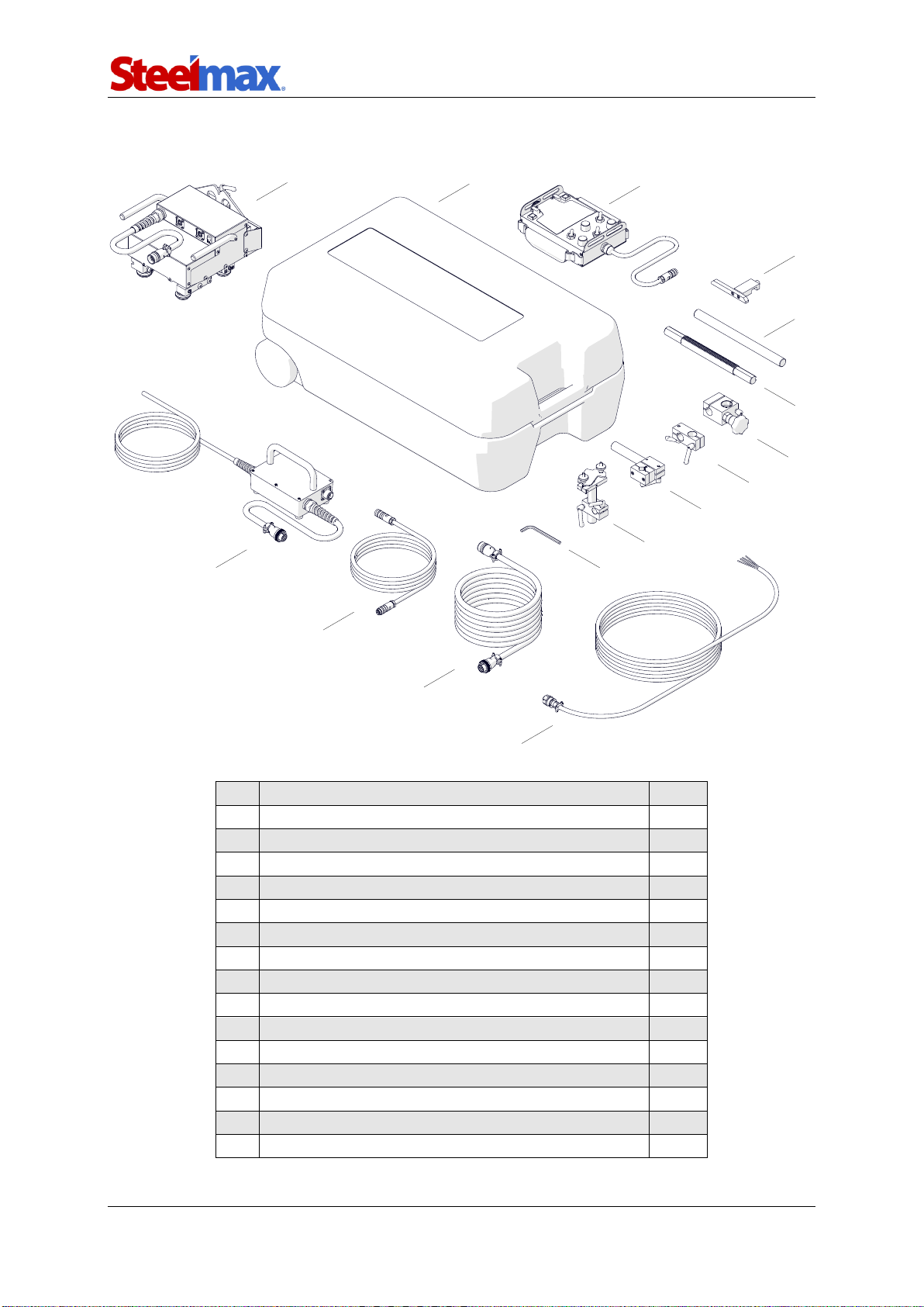
1.3. Equipment included
1
Carriage
1 unit
2
Plastic box
1 unit
3
Remote control
1 unit
4
Contact block
1 unit
5
300 mm (12″) rod
1 unit
6
300 mm (12″) rack with 180 mm (7″) adjustment
1 unit
7
Rack holder
1 unit
8
Clamping block with levers
1 unit
9
Short rod torch holder with clip
1 unit
10
Cable anchor
1 unit
11
6 mm hex wrench
1 unit
12
6.5 m (21 ft) arc ignition cable
1 unit
13
5 m (17 ft) power cable
1 unit
14
3 m (10 ft) remote control cable
1 unit
15
Power supply*
1 unit
–
Operator’s Manual
1 unit
* 230 V, 115 V, or 42 V depending on the order
12
1
3
4
7
8
9
10
11
13
14
15
5
6
2
Rail Runner 2
Rail Runner 2 –Operator’s Manual
6
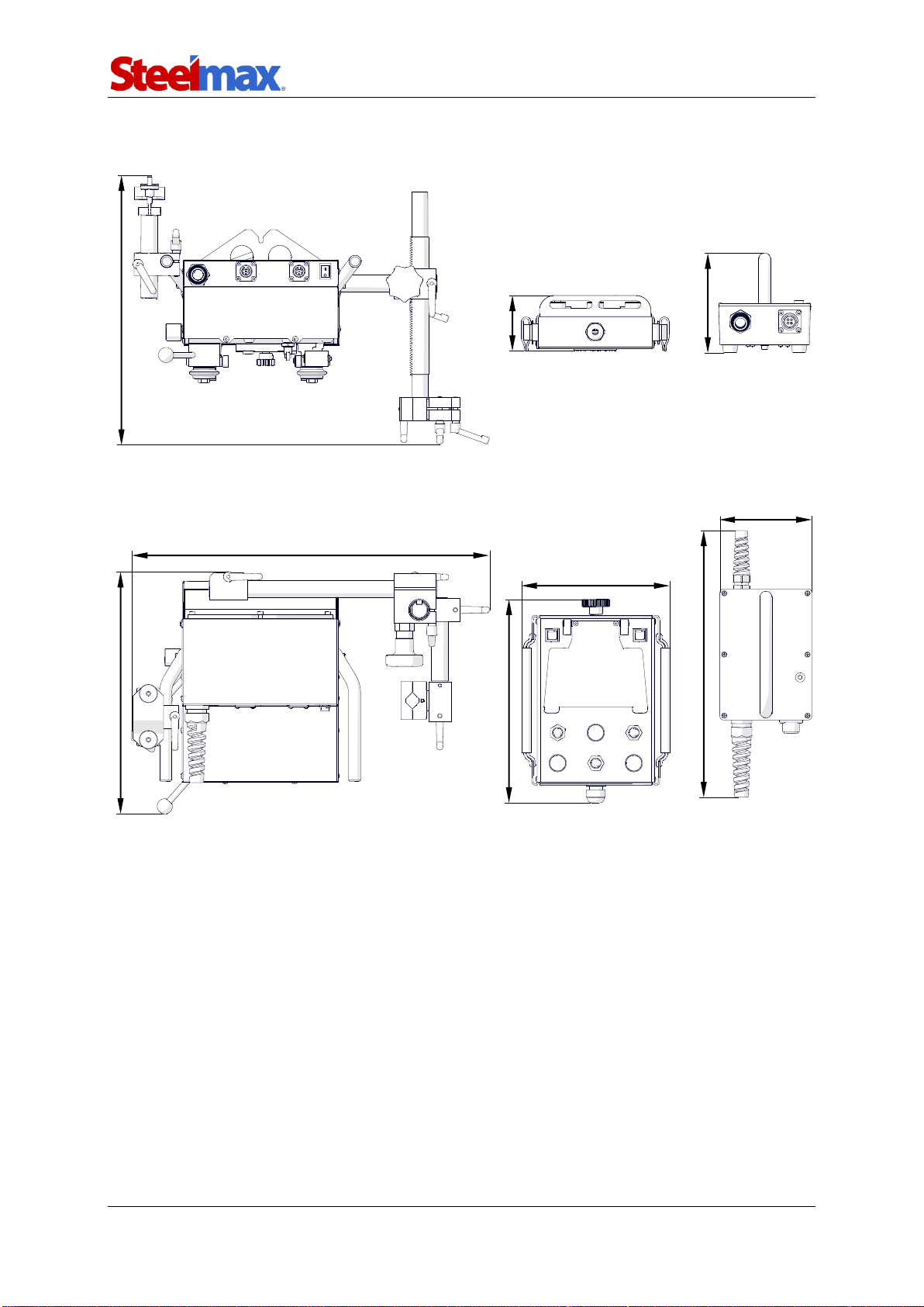
1.4. Dimensions
470 mm (18.5″)
195 mm (7.7″)
318 mm (12.5″)
267 mm (10.5″)
350 mm (13.8″)
73 mm (2.9″)
131 mm (5.2″)
354 mm (13.9″)
121 mm (4.8″)
Rail Runner 2
Rail Runner 2 –Operator’s Manual
7
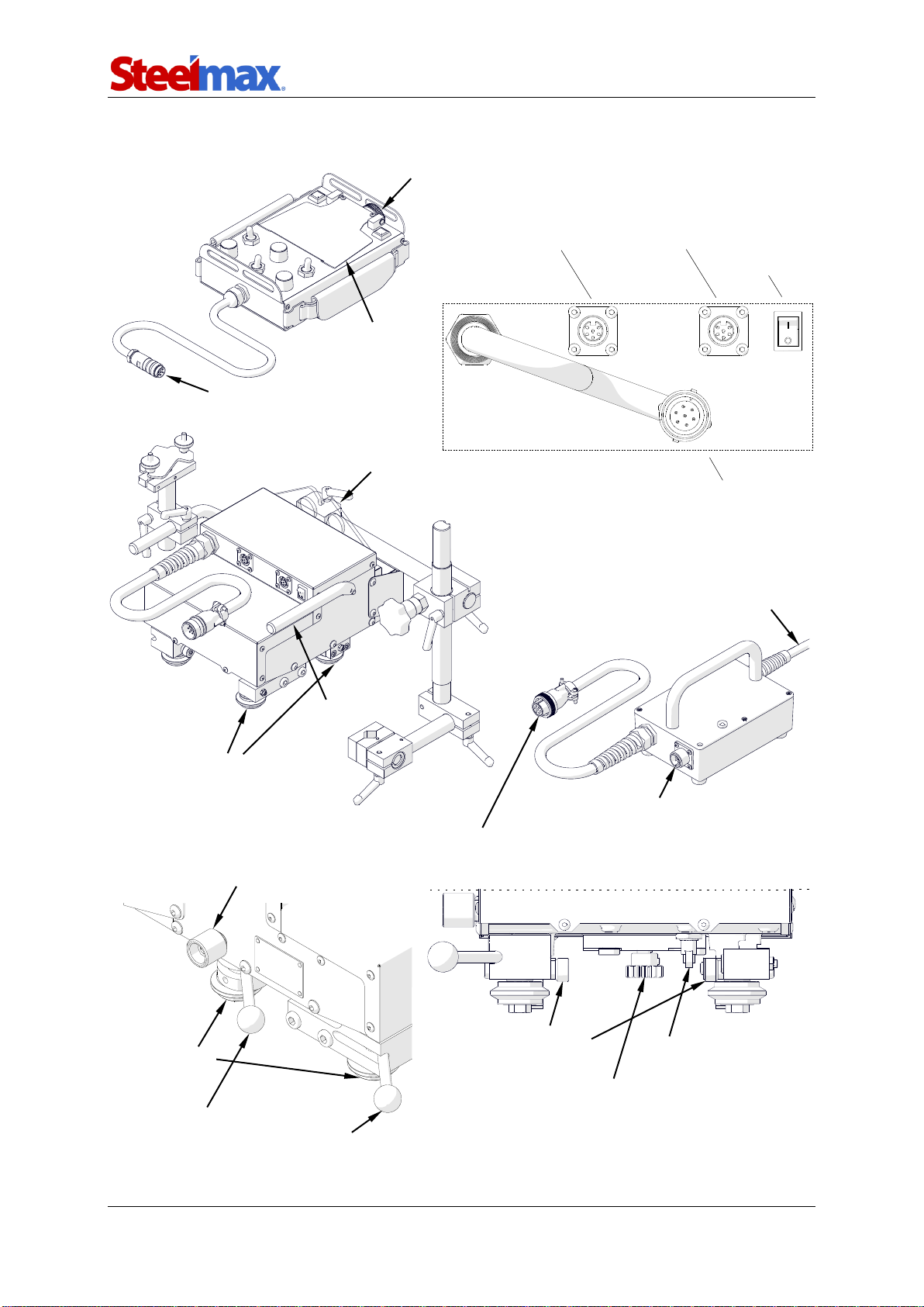
1.5. Design
Arc ignition socket
Carrying handle
Power cord
Rod holder
Passive roller
Knob to attach the remote
control to the carriage
Power switch
Carriage / 3 m (10 ft) remote
control cable connection
Remote control / 3 m (10 ft) remote control cable /
tracking sensor / motorized vertical slide connection
5 m (17 ft) power cable connection
5 m (17 ft) power cable connection
Drive clutch knob
Pressing lever (pressing
rollers are loose in this position)
Pressing roller
Limit switch
Drive gear
Install bracket
Display guard

Rail Runner 2
Rail Runner 2 –Operator’s Manual
8
2. SAFETY PRECAUTIONS
1. Before you start, read this Operator’s Manual and complete occupational safety
and health training.
2. Use the carriage, power supply, remote control, and other equipment only in
applications specified in this Operator’s Manual.
3. Make sure that the carriage, power supply, remote control, and other equipment
have all parts. Make sure that all parts are genuine and not damaged.
4. Make sure that the specifications of the power source are the same as those
specified on the rating plate.
5. Connect the carriage to the power supply by using the power cable. Connect the
power supply to a correctly grounded power source.
6. Do not carry the carriage, remote control, and other equipment by cords or cables.
Do not pull the cords or cables. This can cause damage and electric shock.
7. Keep untrained bystanders away from the carriage.
8. Before you start, ensure the correct condition of the carriage, power supply, remote
control, and other equipment, power source, cords and cables, connections, rollers,
and gear.
9. Keep the carriage, power supply, remote control, and other equipment dry. Do not
expose them to rain, snow, or frost.
10. Keep the work area well lit, clean, and free of obstacles.
11. Do not use near flammable materials, or in explosive environments.
12. Transport and position the carriage by using the carrying handles.
13. Install the carriage only on the supplied track.
14. Make sure that the gear and rollers are clean.
15. Plug the cords and cables into sockets only after you set the power switch to ‘O’.
16. Keep the sockets clean. Do not use high pressure during cleaning.
17. Install only torches whose diameter matches the diameter of the torch holder.
18. Hang the cables to decrease the load of the carriage.
19. Do not bend the semi-flexible track to a radius less than 5 m (16 ft).
20. Use the rigid track only on flat surfaces.
21. At heights, protect the carriage and the track from falling. To do this, use chains
(not included) to attach the leftmost and rightmost magnetic units of the semi-

Rail Runner 2
Rail Runner 2 –Operator’s Manual
9
flexible or rigid track to a stable structure. To protect the carriage, attach a chain
to a carrying handle. Make sure that the chains are not loose.
22. Do not stay below the carriage or the track that is put at heights.
23. Use eye protection (helmet, shield, and screen), hearing protection, gloves, and
protective clothing during work. Do not use loose clothing.
24. Before each use, make sure that the carriage is not damaged and no part is
cracked or loose. Make sure to maintain correct conditions that can have an
effect on the operation of the carriage.
25. Do not try to stop the travel by hand. To stop, set the travel direction switch to ‘O’.
26. Maintain only after you unplug the carriage from the power source.
27. Repair only in a service center appointed by the seller.
28. If the carriage falls from any height, is wet, or has any damage, stop the work and
promptly send the carriage to the service center for check and repair.
29. Do not leave the carriage unattended during work.
30. If you are not going to use the carriage, remove it from the worksite and keep in a
safe and dry place.
Rail Runner 2
Rail Runner 2 –Operator’s Manual
10
3. STARTUP AND OPERATION
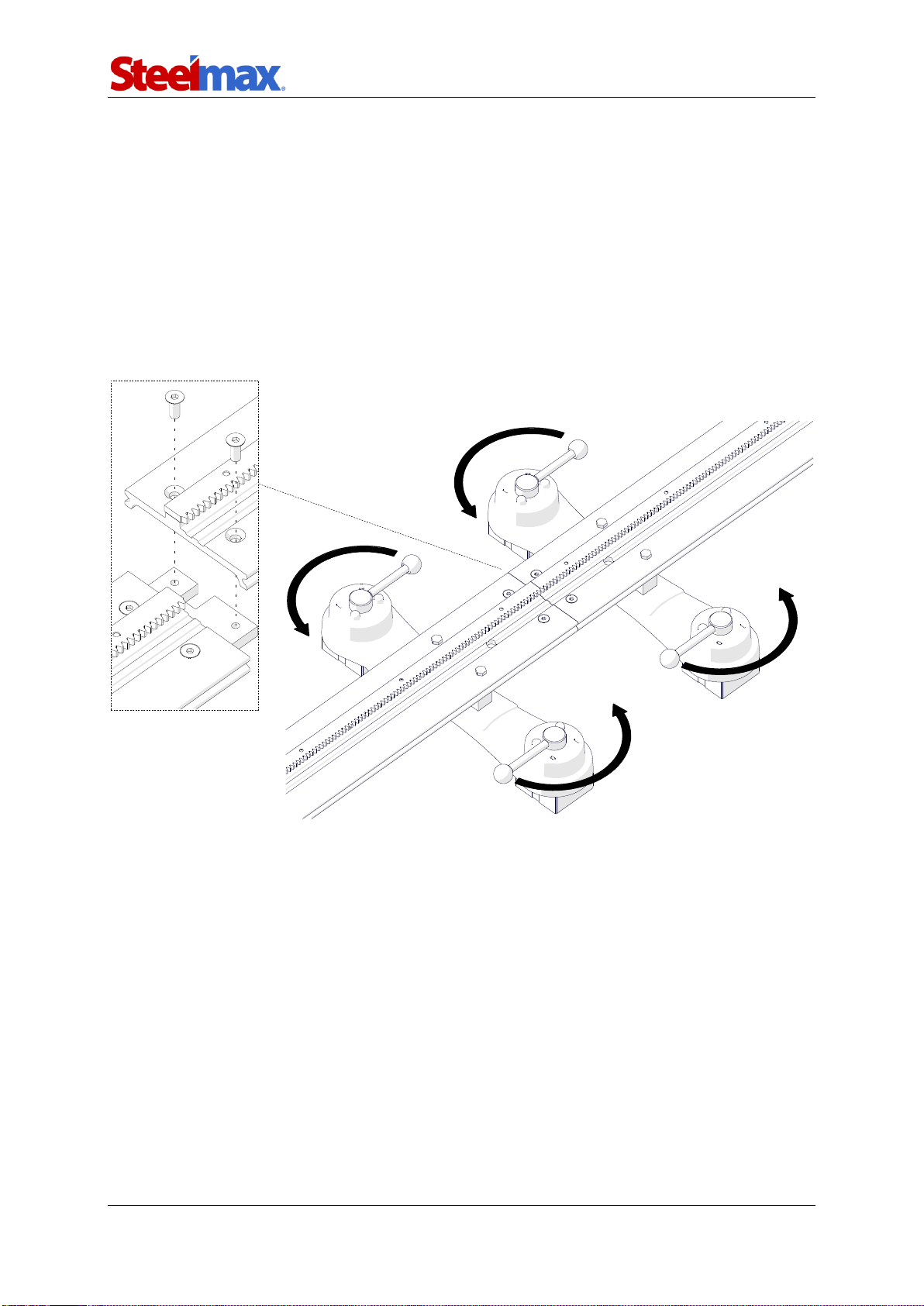
3.1. Assembling the semi-flexible or rigid track
Connect magnetic units to the rail, and put it on the workpiece. Use the 4 mm hex
wrench to attach more rails (1, Fig. 1). Then, set the levers of the magnetic units to ‘I’
(2). This will clamp the track to the surface.
When working in PC/2G welding position, put the track so that the teeth of the
racks point down.
Fig. 1. Connecting the rails and clamping the magnetic units to the surface
If a semi-flexible rail is put on a curve, before you attach more rails use the 4 mm hex
wrench to loosen the screws of the connecting plates (1, Fig. 2) and of the racks (2).
Next, attach the rails, clamp them with levers, and then tighten the connecting plates.
Put the rack adjustment tool (not included) into the hole (3), and rotate the tool to the
left (4) to remove the gap (5) between the racks. Then, tighten the leftmost screw and
the rightmost screw of each rack (2).
1
2
Rail Runner 2
Rail Runner 2 –Operator’s Manual
11
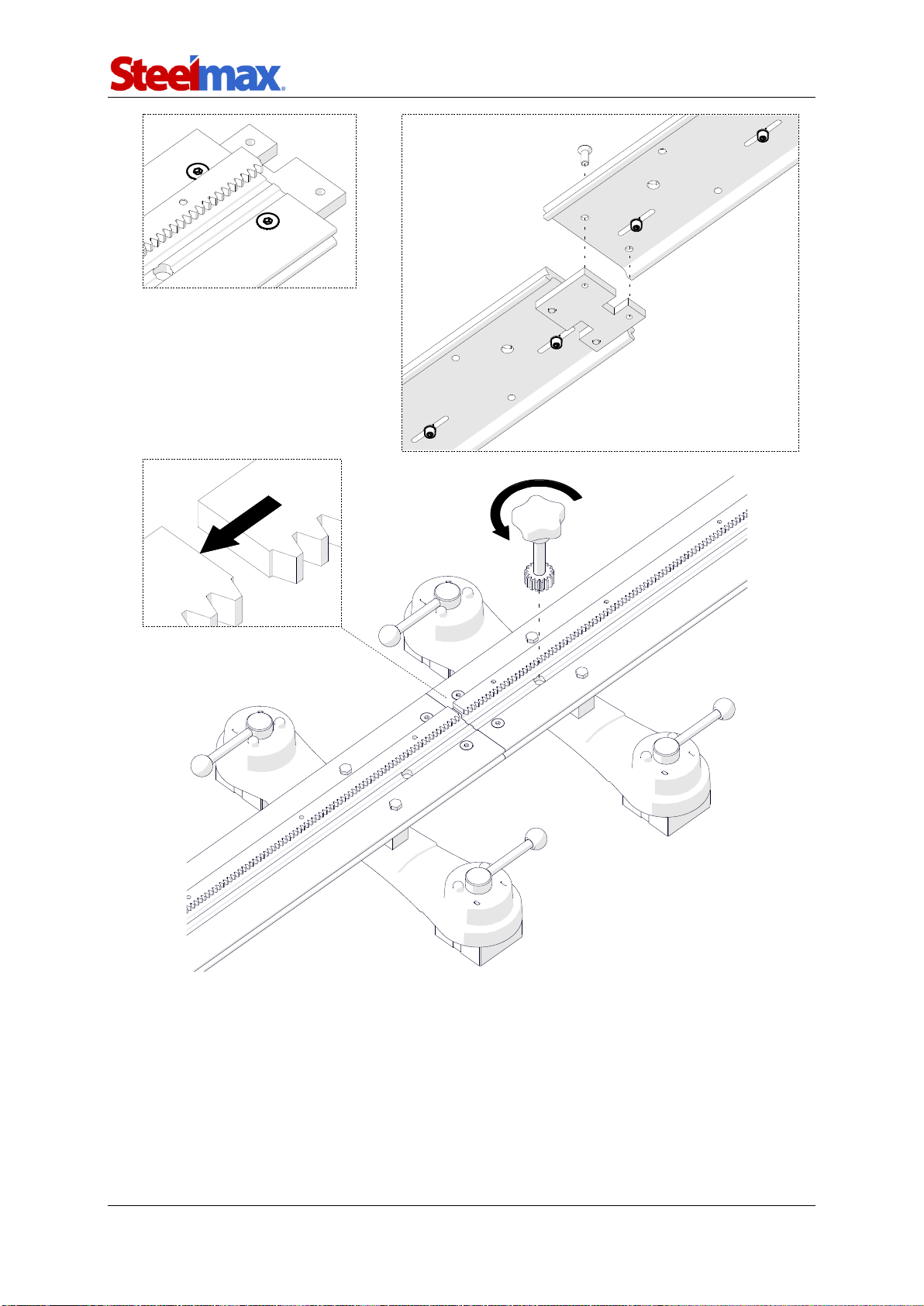
Fig. 2. Removing the gap between the racks of a semi-flexible track
1
2
5
3
4

Rail Runner 2
Rail Runner 2 –Operator’s Manual
12
3.2. Assembling the ring track
Select the track that matches the outer diameter of the round workpiece. Use the
4 mm hex wrench to attach the supports to the rails (1, Fig. 3). Next, on all supports,
retract the bolts (2, or screws) as much as possible.
Fig. 3. Connecting the supports to the rails
Put the workpiece vertically, and then put the rails onto the workpiece so that the
teeth of the racks point down. Next, for all rails, use the 12 mm hex wrench to set
the hinge as shown in Fig. 4. Then, put the lock pin through the holes (1), and then
rotate the wrench (2) to connect the rails.
1
2
2
Screw with plastic foot
25 mm (1″) adjustment range
Bolt
25 mm (1″) adjustment range
Screw with magnet
25 mm (1″) adjustment range

Rail Runner 2
Rail Runner 2 –Operator’s Manual
13
Fig. 4. Connecting the rails of the ring track
Use the 13 mm flat wrench to adjust the bolts (or the screws by hand) until they are in
contact with the workpiece (1, Fig. 5). Adjust each support equally to make the track
concentric to the workpiece. Lock the supports with the nuts (2) or levers.
Fig. 5. Attaching the ring track to the workpiece
1
2
2
1

Rail Runner 2
Rail Runner 2 –Operator’s Manual
14
3.3. Positioning on a straight track
Set the power switch, arc ignition switch, oscillation switch, and travel direction
switch to ‘O’. Next, set the levers to OFF (1, Fig. 6), and then loosen the knob (2)
fully to retract the gear (3). Then, put the carriage so that the install brackets are on
the rail (4, 5).
Fig. 6. Putting the carriage on a straight track
Install bracket
Install bracket
2
1
3
5
Gear
retracted
4
Rail Runner 2
Rail Runner 2 –Operator’s Manual
15
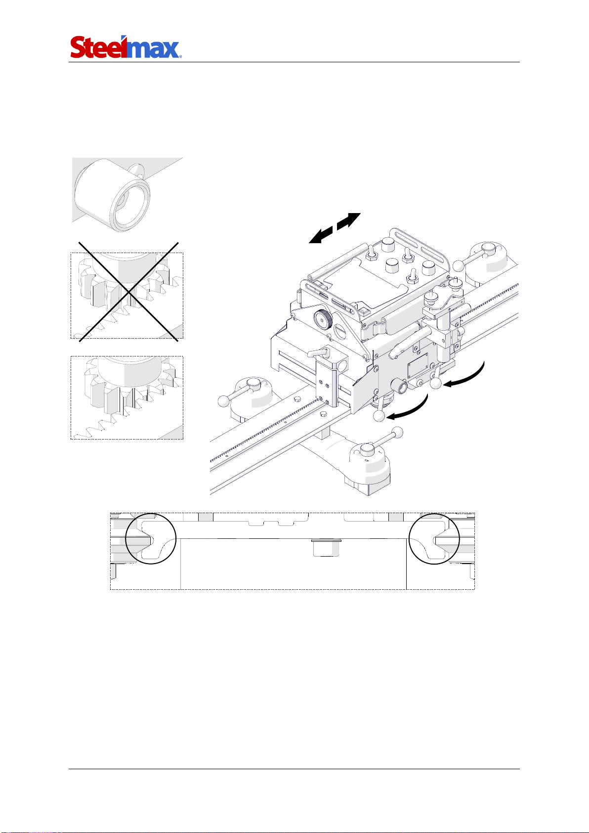
Set the levers to ON (1, Fig. 7) to put the rollers into the grooves (2). Then, while
moving the carriage slightly left or right, tighten the knob (3)to engage the gear of the
carriage with the rack of the rail (4). However, do not tighten the knob with too much
force. Keep some backlash between the gear and rack.
Fig. 7. Engaging the carriage with the track
3
Not engaged
×
Engaged
✓
1
1
2
2
4
Rail Runner 2
Rail Runner 2 –Operator’s Manual
16
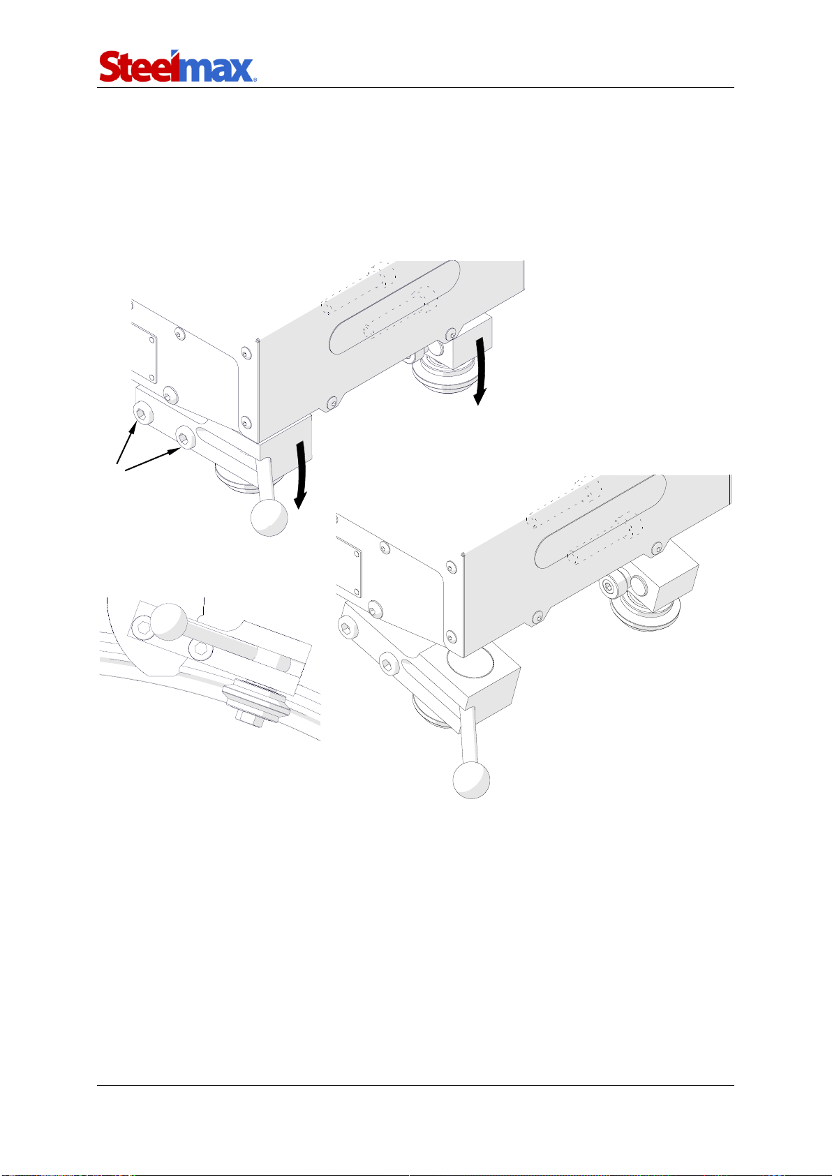
3.4. Positioning on a curved track
Use the 6 mm hex wrench to loosen four screws (1, Fig. 8), and then put the carriage
on the track. Rotate two roller brackets (2) to put the rollers into the grooves, and
then set the levers to ON (3). Next, move the carriage left or right and make sure that
it moves smoothly. Then, tighten the screws (1) and the knob (4).
Fig. 8. Rotating the rollers for a curved track
1
2
2
3
Rail Runner 2
Rail Runner 2 –Operator’s Manual
17
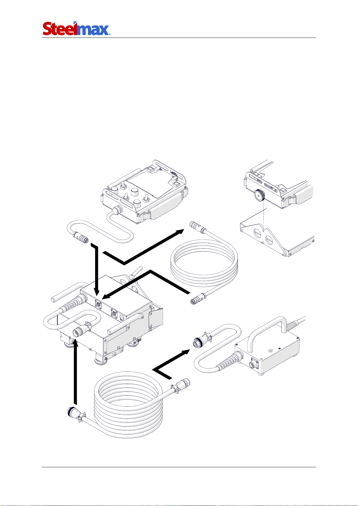
3.5. Preparing and connecting
At heights, protect the carriage and the track from falling. To do this, use chains
(not included) to attach the leftmost and rightmost magnetic units of the semi-flexible or
rigid track to a stable structure. To protect the carriage, attach a chain to a carrying
handle. Make sure that the chains are not loose.
Connect the remote control to the carriage directly (1, Fig. 9), if the remote control
will be put onto the carriage, or use the remote control cable (2). Then, use the power
cable to connect the carriage to the power supply (3). Next, connect the power supply
to the power source and put the torch and torch cables into the holders.
Fig. 9. Connecting the carriage
3 m (10 ft) remote control cable
5 m (17 ft) power cable
1
2
2
3
3
Rail Runner 2
Rail Runner 2 –Operator’s Manual
18
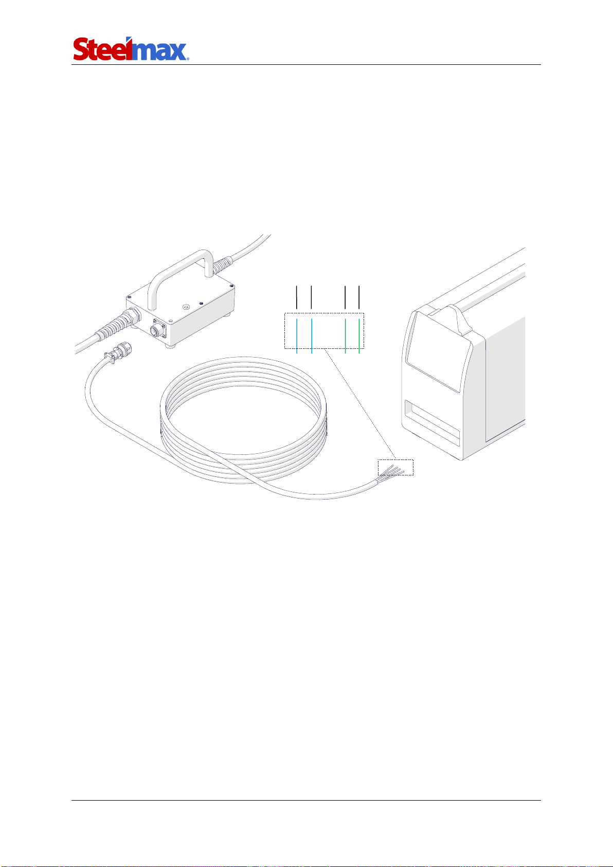
3.6. Connecting to the welding circuits
The carriage can control two torches by using the arc ignition cable plugged into the
arc ignition socket. To do this, refer to the diagram from Fig. 10 and connect one
blue-jacketed wire to one terminal of the welding / plasma cutting circuit. Then,
connect the other blue-jacketed wire to the other terminal of the same circuit.
To control the second torch, connect the green-jacketed wires to the terminals of the
second welding circuit.
Fig. 10. Connecting the arc ignition cable to welding circuits
Make sure that the arc ignition cable is connected correctly. To do this, turn on the
power of the carriage, and then set the arc ignition switch to TEST. This should
enable the arc for a while.
Blue
Blue
Welding circuit 1
Green
Green
Welding circuit 2
Rail Runner 2
Rail Runner 2 –Operator’s Manual
19
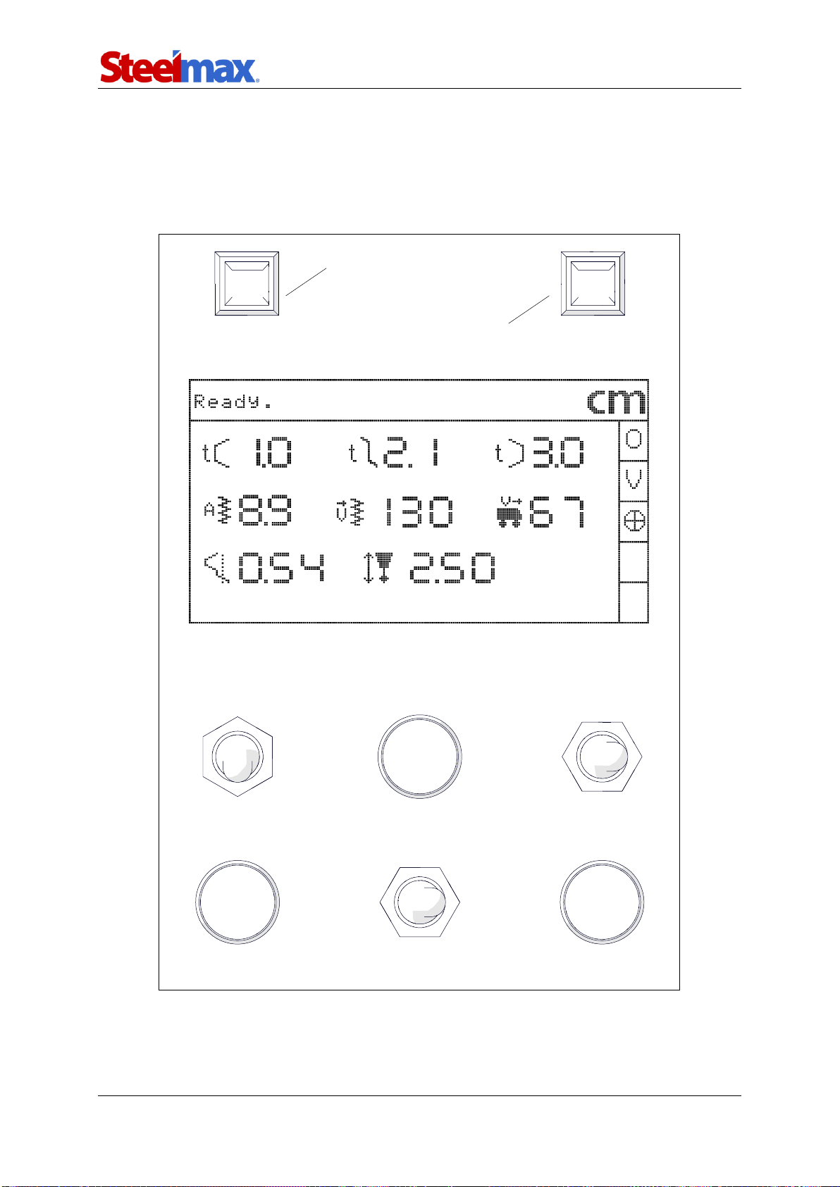
3.7. Operating
Set the power switch to ‘I’ to turn on the carriage. To pause loading to check the
firmware version, press and hold one of the navigation buttons. After you release the
button, the control system loads and the main screen from Fig. 11 shows.
Fig. 11. Control panel with the main screen displayed
Tab. 1 explains the symbols shown on the right of the main screen.
Arc ignition switch
(TEST / O / I)
Travel direction switch
(Forward / O / Backward)
F1
F3
F2
Oscillation switch
(TEST / O / I)
Navigation button 2
Navigation button 1
Rail Runner 2
Rail Runner 2 –Operator’s Manual
20
Tab. 1. Symbols of connected modules
Symbol
Description
Linear oscillator.
Motorized vertical slide (option).
Tracking sensor (option).
Use the knobs to set the required parameters (Tab. 2). Rotate to the right to increase
the valueof the parameter. Rotate to the left to decrease the value.
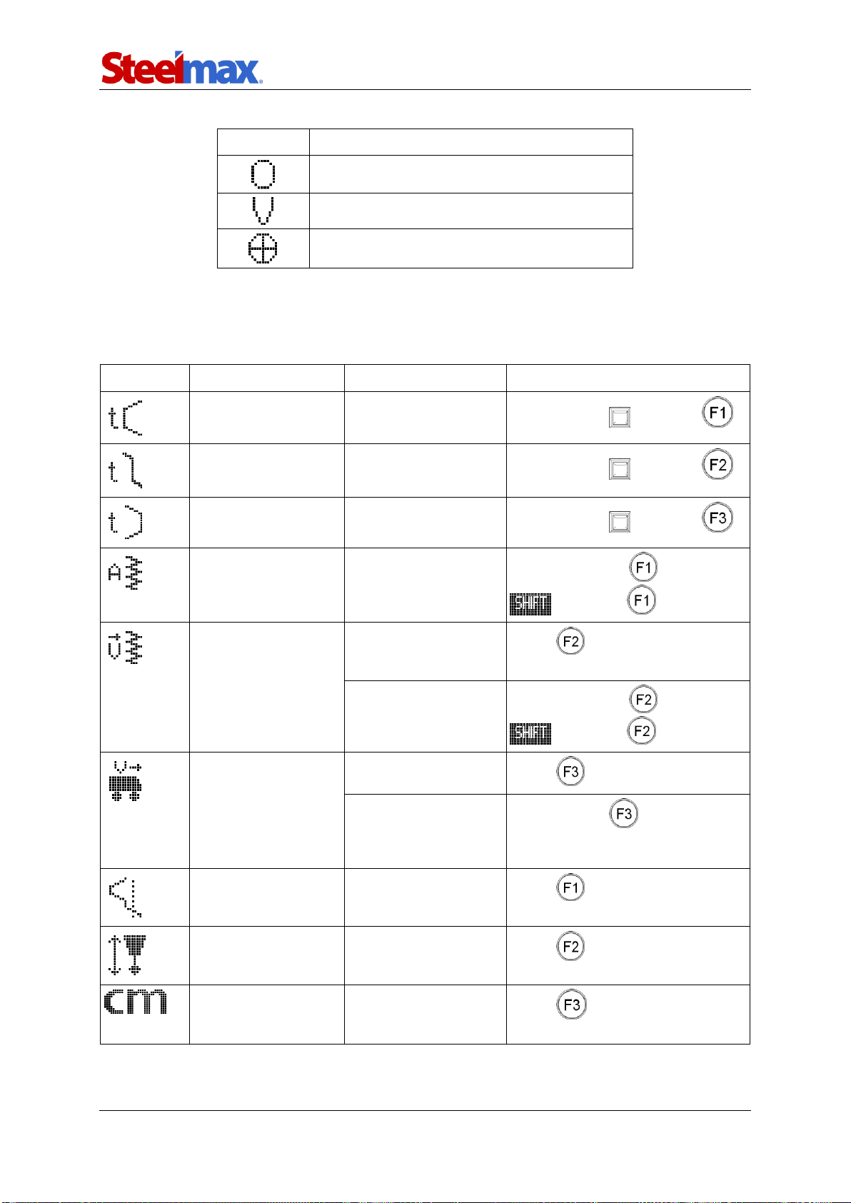
Tab. 2. Parameters shown on the main screen
Parameter
Value
Description
Method of control
0–5 s
[step: 0.1]
Oscillation dwell time in
left position.
Press and hold and rotate
0–5 s
[step: 0.1]
Oscillation dwell time in
center position.
Press and hold and rotate
0–5 s
[step: 0.1]
Oscillation dwell time in
right position.
Press and hold and rotate
0.2–11.8 cm [step: 0.1]
0.1–4.5 in [step: 0.01]
Oscillation width.
Press and release (activates
) and rotate
10–300 cm/min
5–120 in/min
[step: 5/1]
Oscillation speed
(when the vertical slide
is not connected).
Rotate
Oscillation speed
(when the vertical slide
is connected).
Press and release (activates
) and rotate
0–300 cm/min
0–120 in/min
[step: 1/0.5]
Carriage speed.
Rotate
Travel the carriage with
the maximum speed in
the direction set by the
travel direction switch.
Press and hold when the
arc ignition switch is set to ‘O’
From –9.9 to +9.9 cm
From –3.9 to +3.9 in
[step: 0.05/0.02]
Oscillation offset.
Rotate
From –2.5 to +2.5 cm
From –1 to +1 in
[step: 0.02/0.01]
Torch height
(when the vertical slide
is connected).
Rotate
cm
inch
Unit of measure.
Rotate in the correct setup
screen.
Other manuals for Rail Runner 2
1
Table of contents
Other SteelMax Welding Accessories manuals


