Steens Industrier AS 2010 mk IV User manual

R
R
Rev.: 09.02.2010 rgDate: 09.02.2010 rgFil: 373 100 BM manuped 06 EN net.--- -
MANUPED
Art.no.: 373 100
Model 2010 mk IV
I-nr.: 109 200
Ellingsrud Industrifelt, Verkstedveien 25
Post box 254, N-1401 SKI
Phone: +47 64 91 47 00 - Fax: +47 64 87 65 47
e-mail: post@steens-industrier.com
Home page: www.steens-industrier.com
Adjustable resistant
Adjustable height (angle)
Digital counter
speed•
distance•
watch•
Chair-/wheel plates included

U S E R M A N U A L
R
Rev.: 09.02.2010 rgDate: 09.02.2010 rgFil: 373 100 BM manuped 06 EN net.--- -
Warranty
Steens Industrier AS does not have any responsibilty for faults in the content
of this material, for accusingly damage in relations with delivering, use or
recycling of this material.
Steens Industrier AS does not have any responsibility or any guaranty if the
use of this apparatus is not in conjunction with the field of use and meaning.
Technical specifications can be changed with out notice.
© Copyright 2008 - 2010
Steens Industrier AS claims all the rights to this document on the base of
Norwegian law. Reuse, copying complete or fragmentally, may not be done
without our confirmation.
Steens Industrier AS have the right to change the information in this document
without notice.
Publications:
Fil: 373 100 BM manuped 06 EN net.---
First issue: March 2008
Second issue; February 2010
Ellingsrud Industrifelt, Verkstedsveien 25
Post box 254, N-1401 SKI
Phone: +47 64 91 47 00 - Fax: +47 64 87 65 47
e-mail: post@steens-industrier.com
Home page: www.steens-industrier.com
CONTENT
• Foreword
Important symbol•
• Receiving and check out
• Content in the box
• Assembling, preparation and test of functions
• Parts and definitions
Fields of use•
• Product description
• Rules for use
Safety•
• Positions and adjustments
Use of VDO, replacement of battery, setting, programming•
• Cleaning
Maintenance and service•
Base setting of resistance•
Retighten the rim•
• Problems during use
• Accessories
• Technical data
CE declaration of conformity•
Product guaranty•
Log for product maintenance•
Form for claims•
U S E R M A N U A L
R
Steens Industrier congratulate you for choosing our improved MANUPED
with digital counter. We hope both you and your patient will have a great
and a meaningful training moment with use of this apparatus. Steens In-
dustrier AS have their own fabric with modern machinery at Ski. The firm
have developed and produced treatment apparatus and benches since
1974. The products are sold all over the world under the trade mark;
The firm is all the time focused on delivering product of high quality, ac-
cording to the users needs and wishes. The firm is certified according to
ISO 9001 and develop an produce all products to fulfill the claims of the
day. MANUPEDEN is CE marked and confirming with the relevant active
standards and directives.
This user manual for the MANUPED 373 100, is made based on the qual-
ity philosophy of Steens Industrier and the goal is to give the user an
advantage, all the way, with the new apparatus. Please, read this manual
carefully and give the advice and guidance your attention. Then the ap-
paratus will serve you in many years and you will have our complete
guaranty.
FOREWORD
IMPORTENT SYMBOLS
INFORMATION!
This symbol in the text gives information, making it easier to use the
product and an orientation about special functions.
i
WARNING!
This symbol give a general warning for danger. Please, follow the guidance
to avoid injury on persons and damage to equipment and environment.
SQUEEZING!
This symbol warns for squeezing possibility. Please, pay attention and
follow guidance to avoid injury on persons.
R
Rev.: 09.02.2010 rgDate: 09.02.2010 rgFil: 373 100 BM manuped 06 EN net.--- -
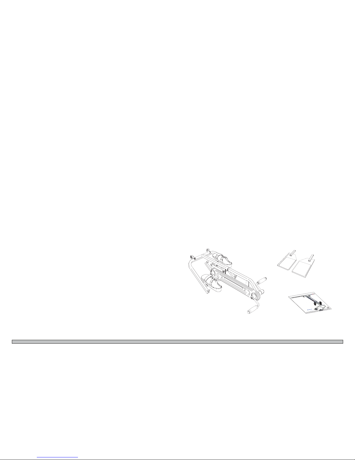
1 MANUPED
1 set of chair/wheel plate.
Battery 12V LR23 (mounted in the transmitter).
Battery 3V CR2032 (mounted in the display).
1 User manual (this one)
RECEIVING and CHECK OUT
CONTENT in the BOX
When receiving the goods, check out order no. model no. recipient in1.
relation to your order.
Check the wrapping for any transport damages. Make a notice on the2.
transport paper and on the form at the end of this booklet. Replace-
ment/repair would not be carried out less proper notice is made and
mailed to us within 10 days.
Rev.:05.02.2008rg
Dato:04.02.2008rg
Fil:373100BM manuped 05.--- -
MANUPED
Art.nr.: 373 100
Modell2008 mk III
I-nr.:100 794
EllingsrudIndustrifelt, Verkstedsveien 25
Postboks254, N-1401 SKI
Telefon:+4764 91 47 00- Faks: +47 64 87 13 74
e-post:post@steens-industrier.com
Hjemmeside:www.steens-industrier.com
Regulerbarmotstand
Regulerbarhøyde (vinkel)
Digitalteller
hastighet
•
distanse
•
klokke
•
Stol-/hjulplatermedfølger

U S E R M A N U A L
R
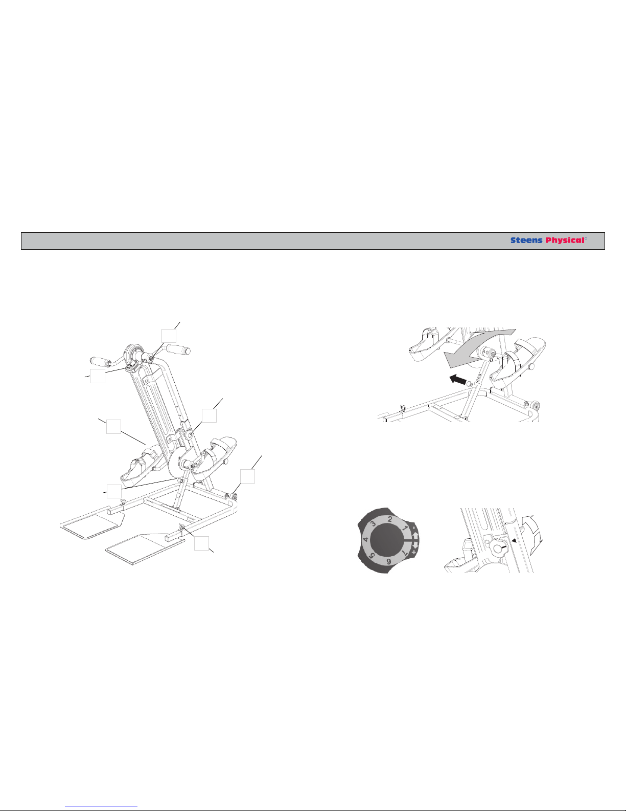
ASSEMBLING, PREPARATION and TEST of FUNCTIONS Make some space on the floor and put down the1. MANUPED.
Raise up the pedal unit2. A.
Put the support tube with the gas spring (3. 1)on the pedal part into the
outer tube (2)on the base frame B
Pull out the snap locker (4. 3) so that it can enter one of the locking
holes. Angle the pedal unit to the desired position, and make sure it
locks properly C.
Put the chair/wheel plates in back end of the base frame (5. 4,5) tighten
the wing screws (6) D.
Unlock the resistant wheel (6. 7), it is tighten throughout transport.
Check now that the digital counter is working. Turn the handle (7. 8)
for some second, a small indicator will appear at the upper left cor-
ner of the display (9).
The apparatus is now ready to be used.8.
Please, make a note in the LOG - at the end of this booklet - date and9.
signature
A
6
12
6
7
5
4
8
9
3
C
B
D
There in no need of tools during assembling.
Rev.: 09.02.2010 rgDate: 09.02.2010 rgFil: 373 100 BM manuped 06 EN net.--- -
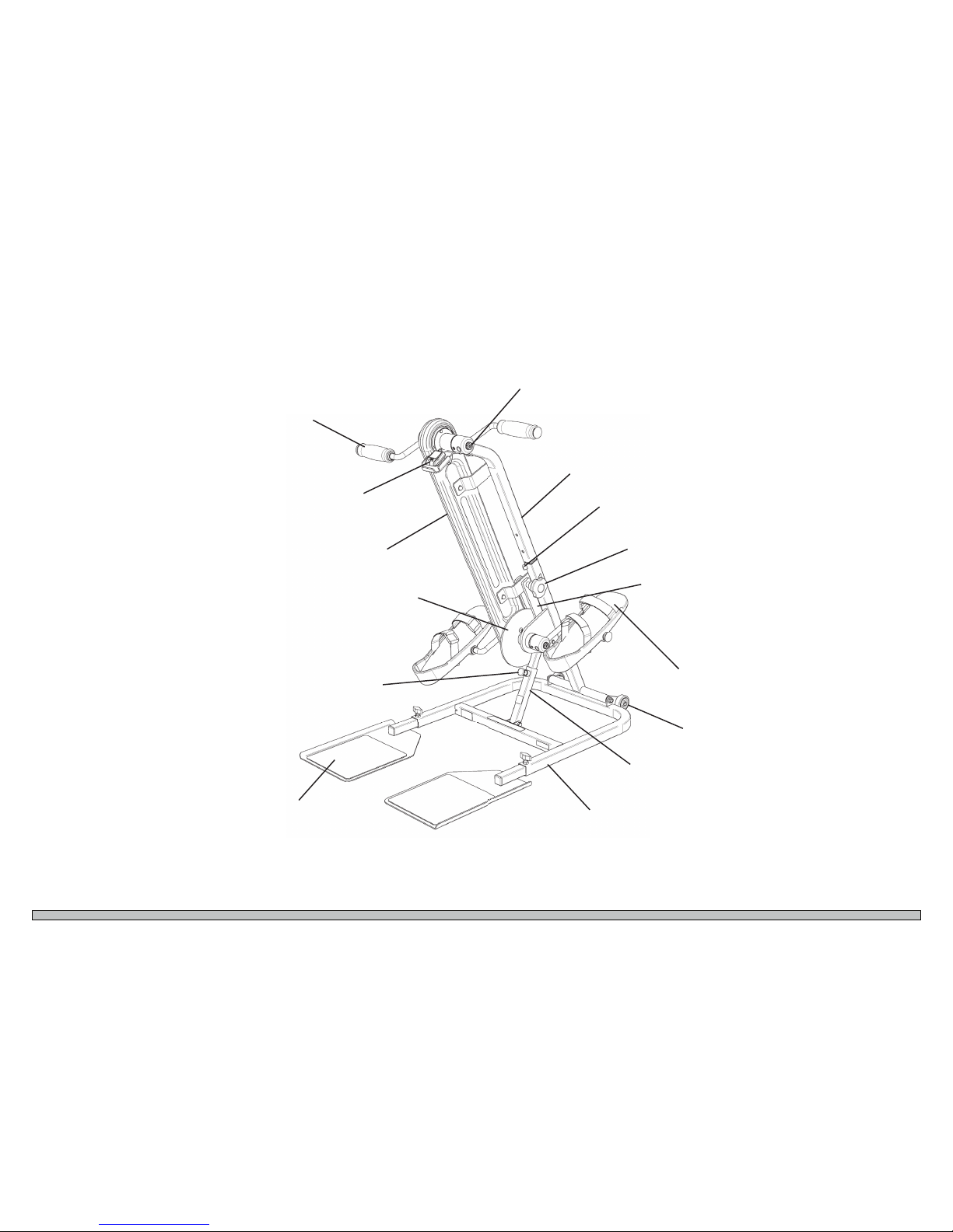
PARTS and DEFINITIONS
RIGHT SIDE
LEFT SIDE
Fix screw with contra nut for
adjustment of arm length.
Handle, gear rim connection to
foot pedals
VDO A4+ digital km counter
with transmitter and receiver
Rim gear cover
Fix screw for tightening
of the rim
Wheel for adjustment
of resistance
Pedals with adjustable foot
straps
Small wheels for moving
the apparatus
Chair/wheel plates with
none slippery cower
Snap lock for height/
angle adjustment
BASE FRAME
Friction disk
Support arm
PEDAL UNIT
ANGLE SUPPORT
U S E R M A N U A L
R
FIELDS of USE
PRODUCT DESCRIPTION
The MANUPED is an apparatus for training of arms and legs. You use it
together with a chair or a wheelchair. The MANUPED is mainly used in
institutions, however it also have a great potential in private homes. It is
developed in order to give elderly a good physical training with softening
of links, stronger muscles, increased condition and blood circulation with
better fitness and increased quality of life.
The MANUPED also has an application where there is a need for coordi-
nation and / or movement between the extremities of various disability or
rehabilitation after injury.
The MANUPED should always be used under the expert guidance of
a therapist.
The MANUPED have foot pedals and hand crank that is connected to
each other and adapted so that the rotational speed is the same. Gear rim
with tightening adjustment, is encapsulated.
Rotation resistance can be adjusted easily with a number marked wheel.
The MANUPED is equipped with a digital counter and the display shows
speed, trip and total “distance” and the clock. VDO Bike Computer A4 +
is used and provides the user with a good quality feeling.
Angle/height to the floor, can easily be adjusted in 5 positions and snap
lock provides a safe setting. The feature is weight balanced with the help
of the compression gas spring and prevents the pedal unit falling and
cause damage.
The MANUPED have floor plates for the chair or wheelchair to set up on.
This ensures that The MANUPED will be at rest during your workout.
Pedal and crank periphery path has two sizes and can be easily adapted
to user needs.
The foot pedal have stops with Velcro and is easy to regulate.
The MANUPED is equipped with 2 casters which facilitates the transfer.
When the device is tilted, it is easy to roll.
i

Rev.: 09.02.2010 rgDate: 09.02.2010 rgFil: 373 100 BM manuped 06 EN net.--- -
RULES FOR USE
SAFETY
The MANUPED is a device that has a low risk of injury when used ac-
cording to intention. Nevertheless, it is necessary to emphasize that it is
your duty to use the MANUPED only for what it is intended.
Always make sure that the MANUPED is in order - none defective part
or features that work improperly.
The person who trains should always sit confidently. Make sure that the
chair / wheelchair stays properly on the plates.
Always make sure that the MANUPED is preset properly to the person
who will exercise:
Set the correct height
Set the appropriate resistance
Set the right pedal and crank length
If desired, 0-set km counter
See the boards are firmly screwed
Place the chair / wheelchair correct relative to the MANUPED
The therapist should always ensure that exerciser/patient are train-
ing correctly. When the workout is optimal the opportunities for er-
ror and injury during training reduced. Always check:
Proper sitting position
Correct height
Proper resistance
Correct intensity
Correct duration.
i
Before use, read the User Manual for full filling the claims of Guar
anties.
Be aware of your
responsibility for safety when using the Apparatus and accessories, to prevent damage and/or
avoid injury. Always get a program and follow the therapists instructions during training.
Før bruk, les brukermanualen for å oppfylle garantikrav.
Vær oppmerksom på ditt ansvar for
sikkerhet når du bruker apparatet og utstyr, for å unngå ødeleggelse og forebygge skader. Få alltid
veiledning og følg instruksjonen til terapauten under treningen.
U S E R M A N U A L
R
POSITIONS and ADJUSTMENTS
ADJUSTMENT OF THE
RESISTANSE
SAFETY SCREWS
FOR PLATES
CHANGING THE LENGTH
OF THE HANDLE
WHEEL FOR EASY
MOVING
CHANGE THE
LENGTH OF THE RIM
ADJUSTMENT OF
THE ANGLE/HEIGHT
0-SET
KM COUNTER
1. SETTING THE HEIGHT / ANGLE
Pull out the snap lock head (A), tilt the balanced handle-support up or down
until correct height. Drop the snap lock and ensure that it locks properly.
2. REGULATION OF RESISTANCE
When the wheel (A) is completely turned on, the resistance is greatest, read
against the small triangle mark on the support tube. When the wheel is turned
turn clockwise the resistance is reduced. Settings in between are indicated
with numbers from 1 to 7.
+
-
B
A
1
2
5
6
4
8
3
Rev.: 09.02.2010 rgDate: 09.02.2010 rgFil: 373 100 BM manuped 06 EN net.--- -
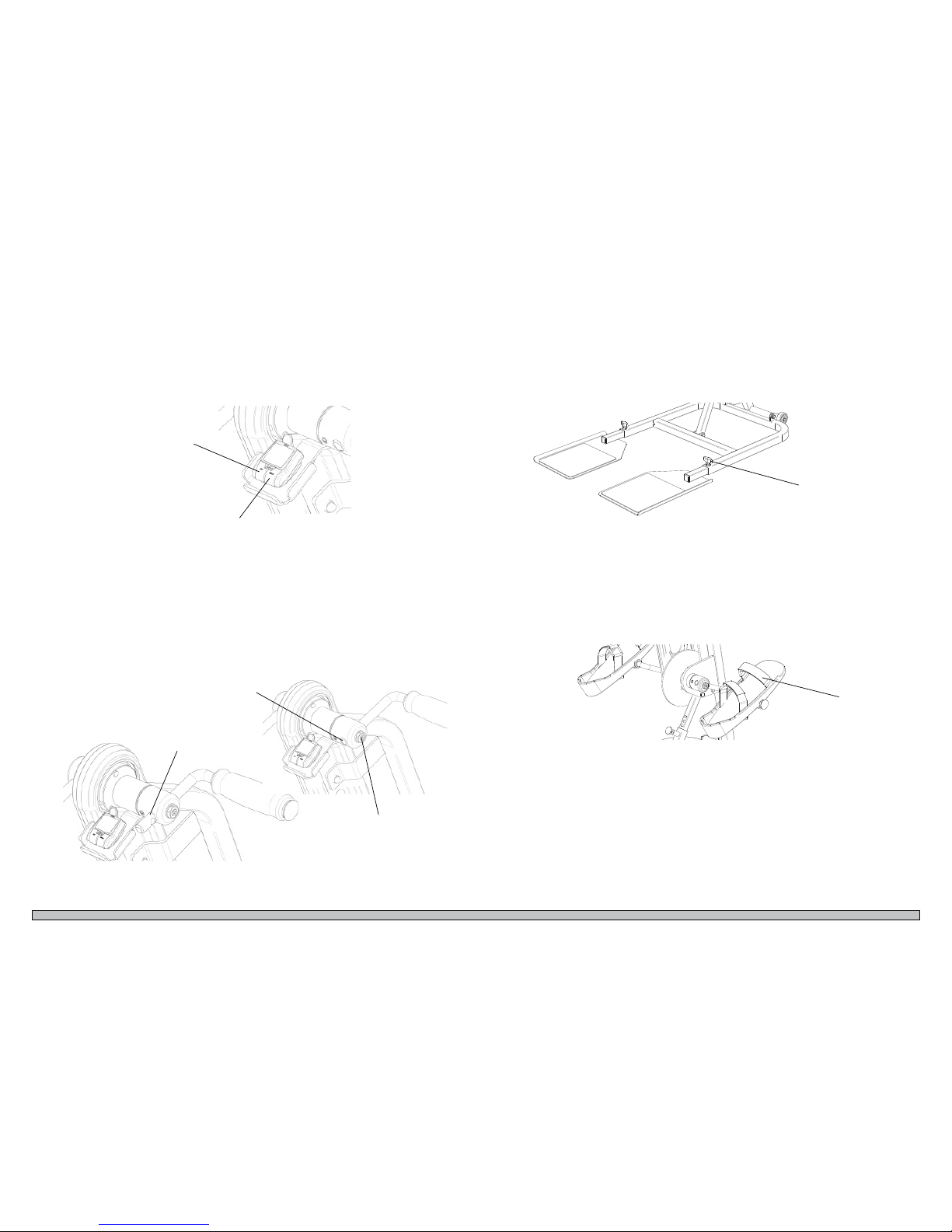
5. WHEEL PLATES AND LOCKING SCREWS.
Always make sure that boards are fully in and lock the lock screw (D) tight.
6. PEDALS AND STRAPS
The straps (E) on the pedals have Velcro lock and are easy to regulate. Make
sure they are correct and appropriate tightened.
4. CHANGE OF ARM LENGTH OF HANDLE AND CRANK
To change the length of the handle and the crank, you needed a 17mm wrench
and a 5mm 6-sided key. Lock nut (C) must be loosened before the set screw
can be turned out slightly. Make sure the set screw hits the dent in the arm
when it is turned on again. Remember to tighten the lock nut at last.
7. MOVING OF THE MANUPED
When the MANUPED is being moved / pushed, turn handle as an arm point-
ing up and move to the resistance wheel completely. Then it’s easier to tilt the
MANUPED on its wheels. It also gives more control when it is rolled.
3. 0-POSITION OF KM COUNTER
Press the SET and MODE buttons simultaneously for 3 seconds. Then the trip
counter is TRP reset to 0 km.
C
D
E
SET button
MODE button
Long arm
(standard)
Short arm
U S E R M A N U A L
R
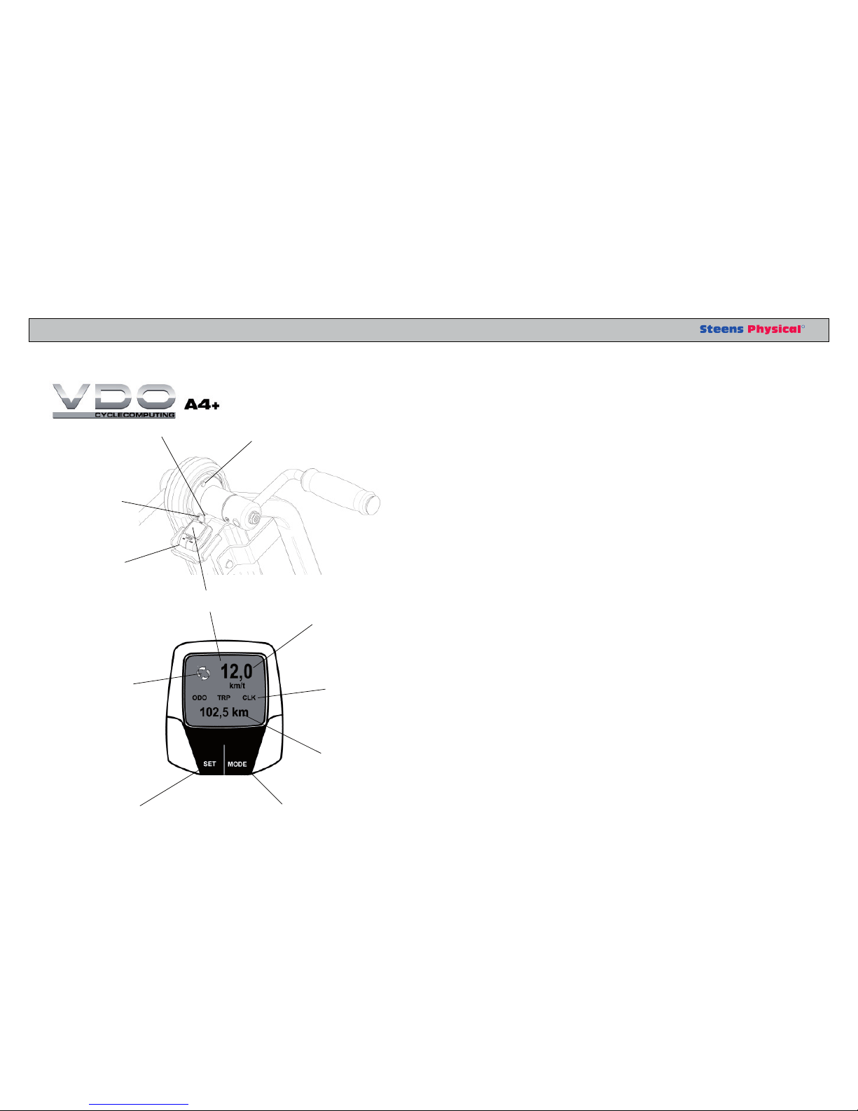
DIGITAL km COUNTER
Magnet
Speed
Mode
Watch
Distance
Indicator
SET button MODE button
DISPLAY
Transmitter
Battery
Battery
1. Taste function
RIGHT BUTTON (MODE button)
In bike mode: Use this button to progress through the ODO, TRP and
CLK screens.
In setting mode: (Set-Mode) Use this key to adjust the values in the
Set-up screen.
LEFT BUTTON (SET button)
Use this button to access the Set-up screens for the wheel size, clock
and odometer.
In SET-Mode: You change the figures.
2. Data Features
CURRENT SPEED (KMH / MPH)
Current speed is displayed permanently on display up to 120 KMT
(75 MPH) with an accuracy of 0.1 KMT
TRAVEL DISTANCE (TRP = TRIP)
Displays the distance to travel for the current trip, up to 999.99 KM
or M. When excess of 999.99, the counting restarts at 000.00
CLOCK (CLK)
Displays the current time in 24-hour format
TOTAL DISTANCE ODOMETER (000)
Showing the total distance, sum of all data of all the individual tours.
Counts up to 99999. The values are KM or M
SLEEP MODE
To extend battery lifetime, the A4 + automatically go into ”sleep”
mode after 3 minutes of use. Only the time will be shown. The wire-
less receiver A4 + will remain active for 3 hours, to allow Auto start
/ stop. In case of non-use, the receiver will be turned off. This is
indicated by a flashing ”CLK” symbol. To reset the computer, press
any key. If the computer is not used, it will turned it self off, no later
than 24:00 midnight. The computer will restart by pushing one of the
keys.
Rev.: 09.02.2010 rgDate: 09.02.2010 rgFil: 373 100 BM manuped 06 EN net.--- -
3. Reset the computer
3.1 RESET APPLICABLE TOUR DATA
To reset the current trip data TRP press SET and MODE buttons
simultaneously for 3 seconds.
3.2 RESET COMPUTER
To reset the computer to factory settings, use a pen and press the
”AC” knob on the back side of the computer.
NOTE: This action will erase all data and all of your setup for
wheel size. Clock and odometer will also be deleted.
4. Replacing of battery and setting
4.1 INSTALLATION OF BATTERY I COMPUTER
VDO A4 + need a battery 3V type CR 2032. Batteries are available
at your dealer (VDO Part No. # 1013). Battery lifetime is around 12
months under normal use. Notice! In case of error display, check the
battery first, before it is taken into claim.
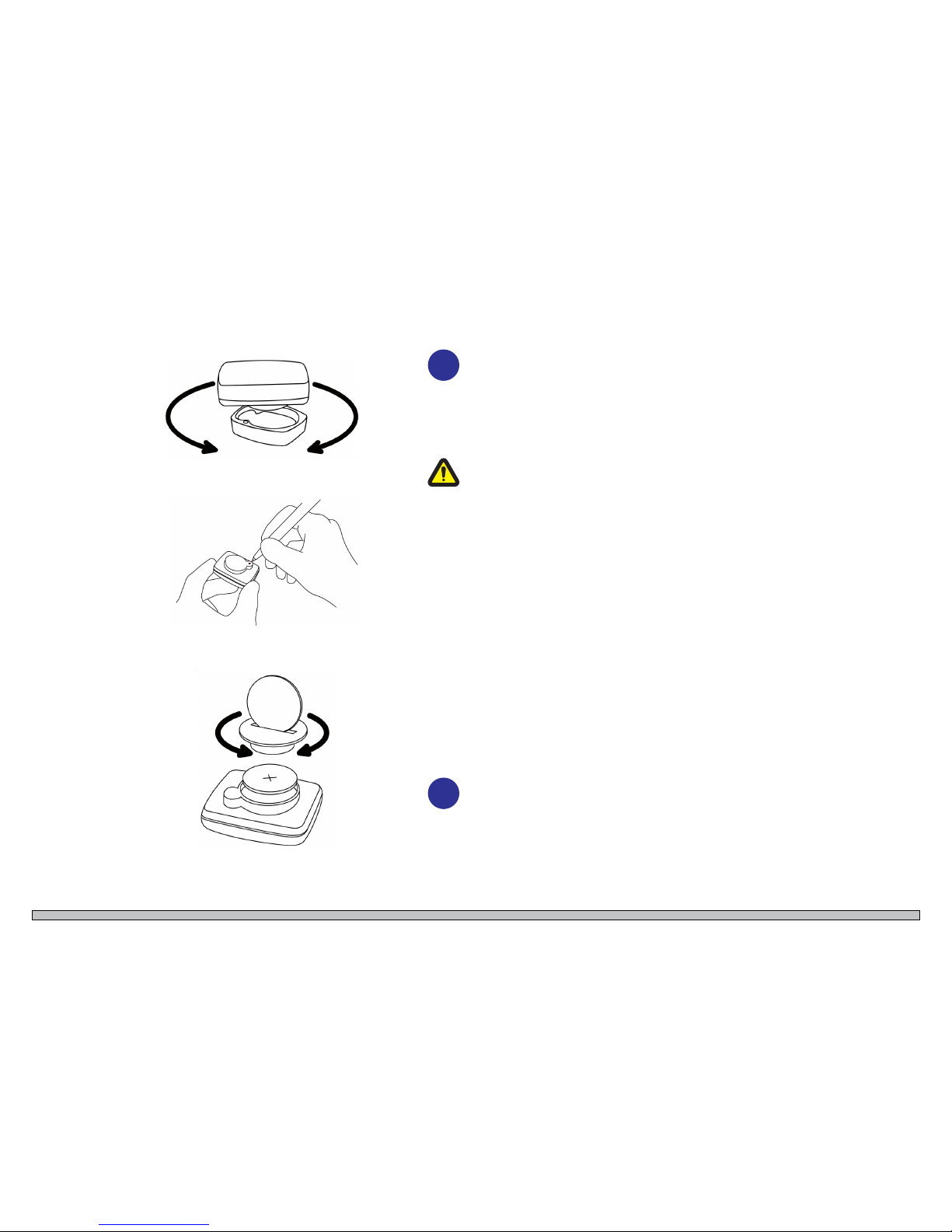
In order to change battery, the computer has to be taken off. Turn it1.
firmly to the left and lift it up.
Remove the battery door with a suitable coin.2.
Place the battery in the battery compartment, + - pole visible. Be3.
careful when installing the battery not to damage the battery connec-
tion.
Replace the battery cover, make sure the rubber O-ring will not be4.
squeezed out of the door. Notice! If the O-ring is damaged it can get
moisture into the battery and the computer can be damaged.
Screw the battery door firmly back in place with a suitable coin.5.
IMPORTANT: During battery replacement, all data and all settings will be
stored in about 20 seconds. In order to save your data, replace the battery
within 20 seconds, otherwise all the settings for the wheel size, clock and
odometer has to be configured again.
Tip: Buy a new battery in time. In order to preserve all data and settings,
change the battery in time. Before you replace the battery, we recommend to
take a note of your wheel size setting and odometer data.
i
i
U S E R M A N U A L
R
4.2 REPLACING THE BATTERY I TRANSMITTER
The VDO A4 + transmitter uses a 12V battery, type LR 23 Batteries are avail-
able at your dealer (VDO Part No. # 1014). Battery life is around 12 months
under normal use.
Remove the battery cover on the transmitter with a suitable coin. This1.
is the side that points down and forwards.
Place the battery in the slot + - pole visible. Be careful when you2.
insert the battery so you do not destroy the battery connection.
Replace the cover. Make sure the O-ring will not be crushed or dis-3.
torted. Then the transmitter will not be waterproof anymore and can
be damaged.
Screw the battery cover firmly back in place with a suitable coin.4.
5. Programming of the km counter
To view an approximate speed and figure out “travelled” distance and other
data, the VDO A4 + km counter set by default, is programmed with a wheel of
a diameter like 700 mm (28 ”) corresponding to a circumference = 2155 mm.
This can be changed if desired (see separate information). The counter is set to
km as the measurement unit.
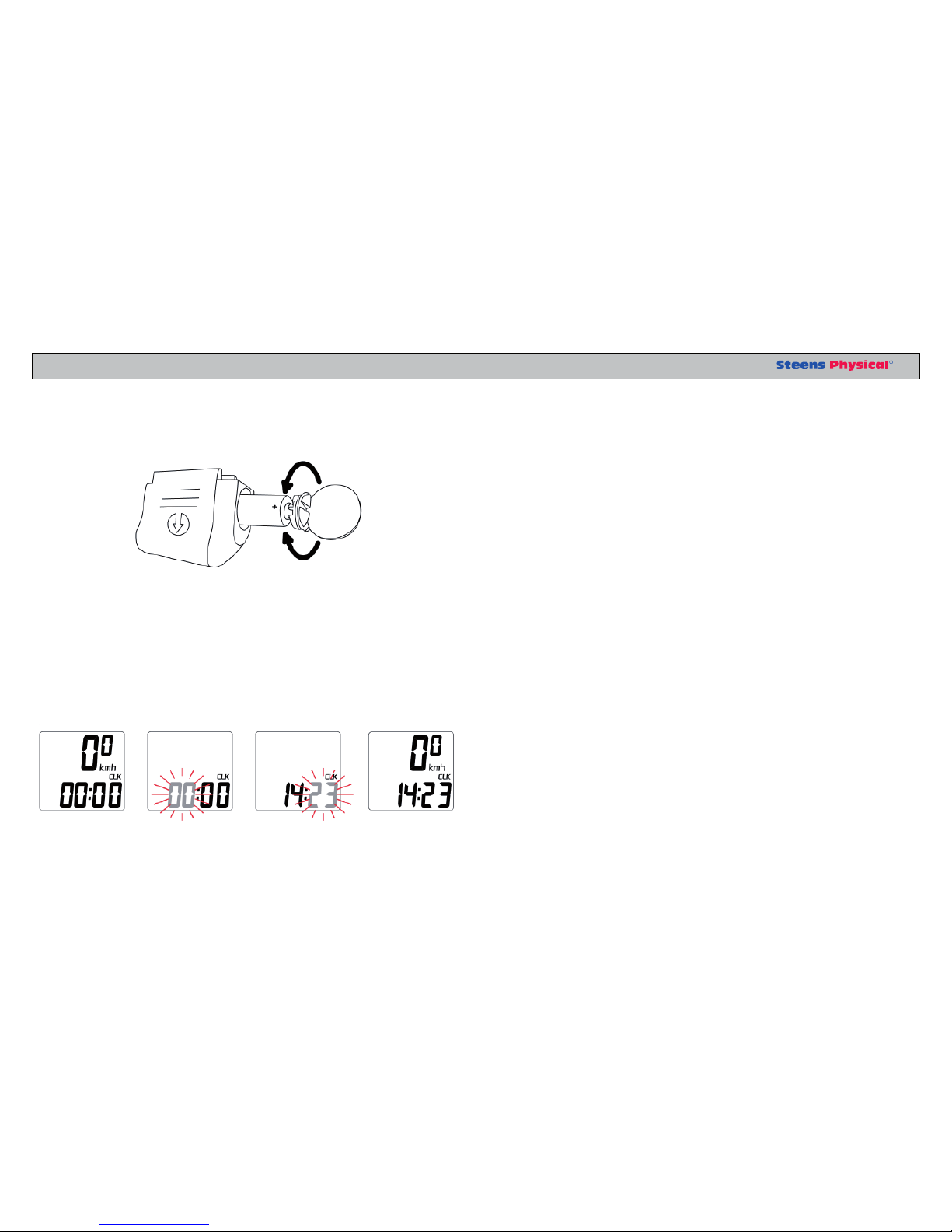
5.1 SETTING THE CLOCK
The VDO A4 + shows the current time in 24:00 hour format.
Take the CLK screen. Press and hold SET button for 3 seconds.1.
Clock SET-Mode will appear on the screen.
Use the MODE button to change the flashing hour figure. Hold the2.
MODE button pushed down for speed setting. Confirm the setting by
pressing the SET button and then move over to the setting of minutes.
Use the MODE button to change the flashing minutes figures. Hold3.
the MODE button pushed down to speed setting.
Press the SET key for 3 sec. Clock setting is completed and CLK4.
screen displays.
Rev.: 09.02.2010 rgDate: 09.02.2010 rgFil: 373 100 BM manuped 06 EN net.--- -
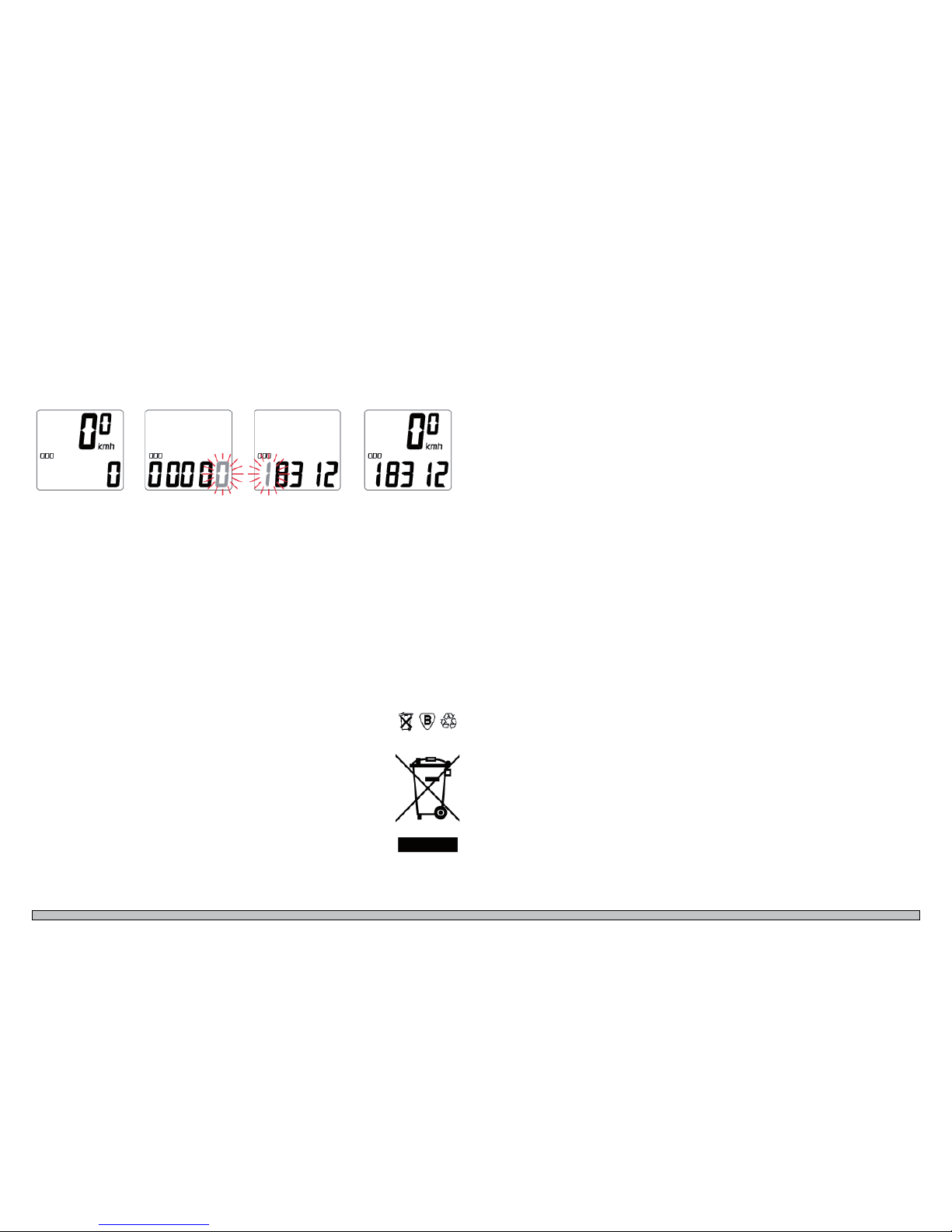
5.2 PROGRAMMING OF ODOMETER
The total distance ODO can be programmed at any time - after battery
change or from previous notes. ODO is a function that shows the total
”trip” distance and always add the last ”trip”.
Take the ODO screen, press and hold SET button for 3 seconds.1.
ODO Set Mode will appear on the screen.
Press the MODE button to change flashing digit to the desired2.
value. Confirm this by pressing the SET button and at the same
time move to the next number that is blinking.
Repeat STEP 1 and STEP 2 until all numbers are programmed3.
as desired.
Press the SET key for 3 sec. to save the ODO programming and4.
return to the ODO screen.
6. Errors and Testing
- If the screen is black, it will be necessary to replace the battery.
- If the screen for some reason is blank or it shows an irregular display
after a battery change, press the AC button on the back side of the com-
puter. This action will erase all data and all settings, and requires new
settings of the clock and odometer.
- If the indicator does not go around it will be necessary to replace the
battery in the transmitter.
7. Recirculation of the battery
This product is consistent with EU Directive 2002/96/EC. The symbol
on the product or on its packaging indicates that this product should not
be treated as ordinary housekeeping waste. Instead it shall be submit-
ted to the collection station for recycling of electronic equipment. When
insure proper waste handling, you will help preventing negative conse-
quences for the environment and human health. In other case, procedure
can cause improper waste handling of this product. For more informa-
tion about recycling of this product, please contact your nearest waste
depot, waste handling service or your dealer of the product.
U S E R M A N U A L
R
CLEANING
MAINTENANCE AND SERVICE
The MANUPED should be cleaned with light soapy water and nearly
dry cloth when needed or at least 1once a year.
The MANUPED is not designed to withstand machine washing or any
use of high pressure cleaners.
Max, washing temperature 80°C, pH between 5 and 7
The MANUPED does not require any special presides of service or
maintenance. But, it is important to check that all functions are working
properly.
The device has no lubrication points. It is designed and manufactured so
lubrication of any kind not is required.
Make it a habit to log all the checks at the back of the user manual.
Complete control at least once annually. Check the following points:
Check and tighten loose screws.1.
Check and replace defective or missing parts.2.
Check straps for pedals3.
Check gear rim. Adjust tightening if required and always when4.
the crank and pedals can be turned asynchronous.
Check batteries. To ensure safe operation of the digital km5.
counter, you will need to replace the battery in the transmitter
and receiver at least 1 time per year.
i
Rev.: 09.02.2010 rgDate: 09.02.2010 rgFil: 373 100 BM manuped 06 EN net.--- -
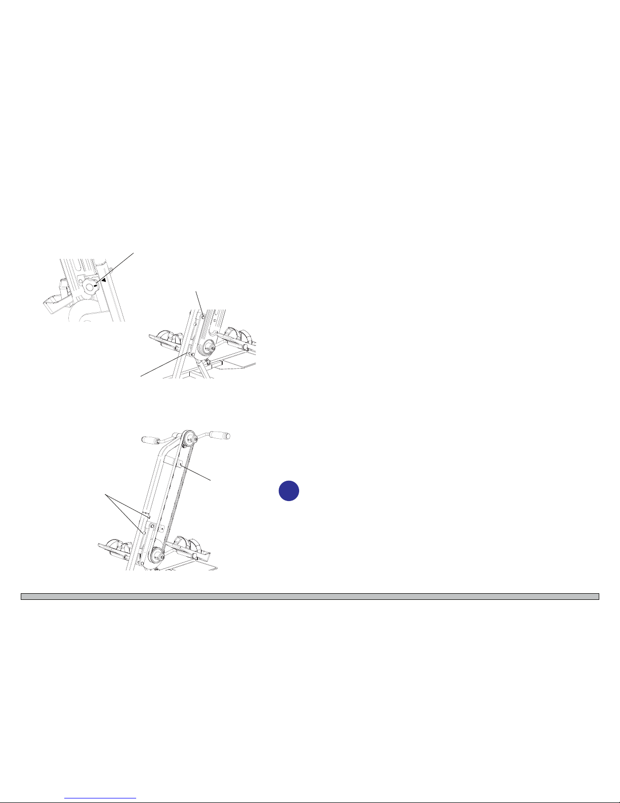
BASE SETTING OF RESISTANCE
RETIGHTEN THE RIM
STARTING POINT: Resistance unit is correctly and loosely mounted.
The brake pads resting on their respective pins. Follow the procedure
below to adjust the resistance knob and nut:
Tighten the steering wheel. Note the 0 point in relation to the1.
triangle mark (1) on manuped tube.
Now turning the wheel so far that the head of the screw can be2.
turned to correct position in its recess (2).
Turn the wheel quite tight and check that the 0 point is in line3.
with triangle mark. If needed, repeat step 2.
Turn the wheel 1 revolution up and now adjust the nut (3) so4.
that the brake pads just allow the disc to run freely. Nut is fitted
with locking means, so that it does not come out of position
during use.
Tighten the wheel completely and check that the friction is5.
working. If the handle still is easy to turn, the nut has to be
tighten some more, repeat step 4.
Follow the steps below when the gear rim aught to be tightened:
Disassemble the cover, remove the nut caps and unscrew nuts.1.
Loosen the upper, inner nut (1) as the permanent cover gets a2.
leeway.
Loosen the set screws (2).3.
If required adjust the pedals and handle so they run synchro-4.
nously.
Take a suitable screwdriver, insert it in the slot between the up-5.
per and lower tubes and turn them from each other until the rim
is tighten properly. NOTE! Do not tighten the rim to hard,
then the MANUPED will run slowly.
Tighten set screws (2)6.
Tighten the inner, upper nut (1)7.
Mount the cover back in place. Ensure that the long slot facing8.
upwards. Turn on the nut and replace the nut cups.
1
2
3
2
1
Here shown without cover.
i

U S E R M A N U A L
R
DISTURBANCE OF FUNCTIONS The MANUPED has few sources that can cause operational disturbanc-
es. Here are mentioned some situations that may arise:
It is difficult to regulate the angle / height ...
Gas Pressure Spring (11) as weight balancing the pedal/handle
support is defect and needs replacement.
The pedals are too heavy to pull around ....
Friction steering wheel (36) is pulled all the way to.
Adjustment nut (32) is too tight.
The pedals are too easy ...
Friction steering wheel (36) is not set correctly
Adjustment nut (32) is the slack
The km counter has black screen ...
Replace the battery (68)
The km counter does not record the activity ...
Replace the battery in the transmitter (69)
Any of the 3 magnet (65) may have fallen off
Foot pedals and handle jumps or runs asynchronously
Adjust and tighten gear rim (24)
Screeching noises ...
Check the reason - repair the error source as soon as possible
Check with a qualified personal when the service should be per-
formed.
- the sooner a fault is repaired, the less risk of danger when used. It also
reduces the risk of more serious consequential damage and more errors.
Wear is reduced and the product gets a longer lifetime.
i

Rev.: 09.02.2010 rgDate: 09.02.2010 rgFil: 373 100 BM manuped 06 EN net.--- -
ACCESSORIES To the MANUPED the following equipment are available:
Long chair/wheel plates - art.no.: 373 100-10
Standard chair/wheel plates - art.no.: 373 100-09
Chair/wheel plate with straps - art.no.: 373 100-02
One piece chair/wheel plate - art.no.: 373 100-06

U S E R M A N U A L
R
TECHNICAL DATA The MANUPED are manufactured in steel and powder coated. Parts that
can be worn out, are chrome plated.
It is not used materials or processes that pollute the environment.
The product and the batteries should be recycled in accordance with ap-
plicable regulations.

(C) Steens Industrier AS reserves all rights to this drawing
in accordance with Norwegian law.
Use, abuse, duplication, communication to third person,
completely or in part, must be cleared with us in advance.
Steens Industrier AS disclaims any liability with regard to abuse of
this drawing, its idea or its content.
Drawing information may change without notice.
Date stamp, signature and ordeing verifies the drawing.
Tittel:
Konstruert Kontrollert: Godkjent:
Toleranser:
NS-ISO 2768-1
Beregning:
Henvisning:
Dato:
Dato: Dato:
Middels Ekstra
grov
Fin Grov Fil:
Erstattet av:
1400 SKI Tlf: 64 91 47 00 post@steens-industrier.com
Steens Industrier AS
Erstatter:
Målestokk:
/
Side/sider
Utgave:
Tegning nr.:Tempus:
Manuped digital
RG
09.02.2010
2 3
Art.nr.: 373 100 MK IV
109200.iam
x
A - 09.02.2010 - rg
109200
-
075
612
970-1075
935
66°-81
a
ADJUSTABLE 5 positions:
1 - 66
a
2 - 69
a
3 - 73
a
4 - 76
a
5 - 81
a
Weight: ca 26.2 kg
This manual suits for next models
1
Table of contents
Other Steens Industrier AS Fitness Equipment manuals

Popular Fitness Equipment manuals by other brands


G-FITNESS
G-FITNESS AIR ROWER user manual

CAPITAL SPORTS
CAPITAL SPORTS Dominate Edition 10028796 manual

Martin System
Martin System TT4FK user guide

CIRCLE FITNESS
CIRCLE FITNESS E7 owner's manual

G-FITNESS
G-FITNESS TZ-6017 user manual

Accelerated Care Plus
Accelerated Care Plus OMNISTIM FX2 CYCLE/WALK user manual


