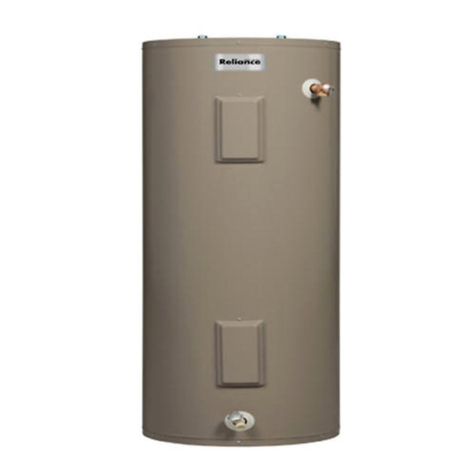
Steibel Eltron DEL 18 Si User manual

Technik zum Wohlfühlen
252252
8984.01
electronic LCD
DEL 18 Si, DEL 21 Si, DEL 24 Si, DEL 27 Si electronic LCD
Deutsch
Elektronisch geregelter Durchlauferhitzer
Gebrauchs- und Montageanweisung
English
Electronically-controlled instantaneous water heater
Operation and installation instructions
Polski
Elektronicznieregulowanyprzepływowyogrzewaczwody
Instrukcjaobsługiimontażu
Česky
Elektronickyřízenýprůtokovýohřívač
Návodkpoužíváníamontáži
Pyccêèé
Ïðîòî÷íûé âîäîíàãðåâàòåëü ñ ýëåêòðîííûì óïðàâëåíèåì
Èíñòðóêöèÿ ïî ìîíòàæó è ýêñïëóàòàöèè

2
Inhaltsverzeichnis
Deutsch Seite . . . . . . 6 - 10
1. Gebrauchsanweisung . . . . . . . . . . . . . . . 6
1.1 Gerätebeschreibung
1.2 Das Wichtigste in Kürze
1.3 Wichtige Hinweise
1.4 Warmwasserleistung
1.5 Temperaturbegrenzung
1.6 Fernsteuerung
1.7 Einstellungsempfehlung
1.8 Erste Hilfe bei Störungen
1.9 Wartung und Pflege
1.10 Gebrauchs- und Montageanweisung
2. Montageanweisung . . . . . . . . . . . . . . 7 - 9
2.1 Geräteaufbau
2.2 Wichtige Hinweise
2.3 Kurzbeschreibung
2.4 Armaturen
2.5 Vorschriften und Bestimmungen
2.6 Technische Daten
2.7 Montageort
2.8 Gerätemontage vorbereiten
2.9 Temperaturbegrenzung
2.10 Wasseranschluss
2.11 Elektrischer Anschluss
2.12 Montage abschließen
2.13 Erstinbetriebnahme
2.14 Betrieb mit vorgewärmtem Wasser
2.15 Sonderzubehör
3. Störungsbeseitigung - Benutzer . . . . . 10
4. Störungsbeseitigung - Fachmann . . . . . 10
5. Umwelt und Recycling . . . . . . . . . . . . . 10
6. Garantie . . . . . . . . . . . . . . . . . . . . . . . . 10
Table of contents
English pages . . . . . . 11 - 15
1. Instructions for use . . . . . . . . . . . . . . . 11
1.1 Description of the unit
1.2 The most important points - at a
glance
1.3 Important notes
1.4 Hot water output
1.5 Temperature limitation
1.6 Remote control
1.7 Setting recommendation
1.8 First Aid in the event of faults
1.9 Care and maintenance
1.10 Instructions for Installation and Use
2. Installation Instructions . . . . . . . . 12 - 14
2.1 Unit structure
2.2 Important notes
2.3 Brief description
2.4 Special fittings
2.5 Regulations and provisions
2.6 Technical data
2.7 Place of installation
2.8 Preparing for unit installation
2.9 Temperature limitation
2.10 Water connection
2.11 Electrical connection
2.12 Completing installation
2.13 Taking into operation for the first time
2.14 Operation with pre-heated water
2.15 Special accessories
3. Fault finding - User . . . . . . . . . . . . . . . . 15
4. Fault finding - Qualified installer . . . . . . 15
5. Environment and recycling . . . . . . . . . . 15
6. Guarantee . . . . . . . . . . . . . . . . . . . . . . . 15
Spistreści
Polskistrona .. 16-20
1.
Instrukcjaobsługi ............ 16
1.1
Opisurządzenia
1.2 Skrótnajważniejszychinformacji
1.3 Ważnewskazówki
1.4 Wydajnośćciepłejwody
1.5 Ograniczenietemperatury
1.6 Zdalnesterowanie
1.7 Zalecanenastawienia
1.8 Pomocprzyusterkach
1.9 Konserwacjaiczyszczenie
1.10 Instrukcjaobsługiimontażu
2.Instrukcjamontażu ......... 17-19
2
.1 Budowaurządzenia
2.2 Ważnewskazówki
2.3 Krótkiopis
2.4 Armatury
2.5 Przepisyizalecenia
2.6 Danetechniczne
2.7 Miejscemontażu
2.8 Przygotowaniedomontażu
urządzenia
2.9 Ograniczenietemperatury
2.10 Podłączeniewody
2.11 Podłączenieelektryczne
2.12 Zakończeniemontażu
2.13 Pierwszeuruchomienie
2.14 Pracazewstępniepodgrzanąwodą
2.15 Wyposażeniedodatkowe
3.Przyczynyusterek-usuwanieprzez
Użytkownika ................. 20
4.Przyczynyusterek-usuwanieprzez
Serwisanta .................. 20
5.Ochronaśrodowiskanaturalnego . 20
6.Gwarancja .................. 20
Obsah
Českystrana .. 21-25
1.Návodkpoužívání ............ 21
1.1 Popispřístroje
1.2 Nejdůležitějšívezkratce
1.3 Důležitáupozornění
1.4 Odběrteplévody-výkony
1.5 Omezeníteploty
1.6 Dálkovéovládání
1.7 Doporučenénastavení
1.8 Prvnípomocpřiporuše
1.9 Údržbaapéčeopřístroj
1.10 Návodkpoužíváníakmontáži
2.Návodkmontáži .......... 22-24
2.1 Uspořádáníohřívače
2.2 Důležitáupozornění
2.3 Stručnýpopispřístroje
2.4 Odběrovébaterie
2.5 Předpisyaustanovení
2.6 Technickádata
2.7 Místopromontáž
2.8 Přípravamontážeohřívače
2.9 Omezeníteploty
2.10 Připojenívody
2.11 Elektricképřipojení
2.12 Ukončenímontáže
2.13 Prvníuvedenídoprovozu
2.14 Provozspředehřátouvodou
2.15 Zvláštnípříslušenství
3.Odstraněníporuchuživatelem.... 25
4.Odstraňováníporuchodborným
instalatérem ................. 25
5.Ekologiearecyklace .......... 25
6.Záručnípodmínky ............ 25
Ñîäåðæàíèå
Ðóññêèé ñòð. . . . . 26 - 31
1.Èíñòðóêöèÿ ïî ýêñïëóàòàöèè . . . . 26
1.1 Îïèñàíèå ïðèáîðà
1.2 Íàèáîëåå âàæíûå óêàçàíèÿ
1.3 Âàæíûå çàìå÷àíèÿ
1.4 Âûõîä ãîðÿ÷åé âîäû
1.5 Òåìïåðàòóðíîå îãðàíè÷åíèå
1.6 Âûíîñíîå óïðàâëåíèå
1.7 Ðåêîìåíäàöèè ïî çàäàíèþ
òåìïåðàòóðû
1.8 Ïåðâàÿ ïîìîùü ïðè
íåèñïðàâíîñòÿõ
1.9 Óõîä è ïðîôèëàêòè÷åñêîå
îáñëóæèâàíèå
1.10 Óêàçàíèÿ ïî ìîíòàæó è
ýêñïëóàòàöèè
2.Èíñòðóêöèÿ ïî ìîíòàæó . . . . . . 27 - 30
2.1 Êîíñòðóêöèÿ óñòàíîâêè
2.2 Âàæíûå çàìå÷àíèÿ
2.3 Êðàòêîå îïèñàíèå
2.4 Ñïåöèàëüíàÿ àðìàòóðà
2.5 Ïðåäïèñàíèÿ è íîðìû
2.6 Òåõíè÷åñêèå õàðàêòåðèñòèêè
2.7 Ìåñòî äëÿ ìîíòàæà
2.8 Ïîäãîòîâêà ê ìîíòàæó óñòàíîâêè
2.9 Òåìïåðàòóðíîå îãðàíè÷åíèå
2.10 Ïîäñîåäèíåíèå ê âîäîïðîâîäó
2.11 Ïîäñîåäèíåíèå ê ýëåêòðè÷åñêîé
ñåòè
2.12 Çàâåðøåíèå ìîíòàæà
2.13 Ïåðâûé çàïóñê â ýêñïëóàòàöèþ
2.14 Ðàáîòà ñ ïðåäâàðèòåëüíî
ïîäîãðåòîé âîäîé
2.15 Ñïåöèàëüíûå ïðèíàäëåæíîñòè
3.Óñòðàíåíèå íåèñïðàâíîñòåé -
ñâåäåíèÿ äëÿ ïîëüçîâàòåëÿ . . . . . . 31
4.Óñòðàíåíèå íåèñïðàâíîñòåé -
ñâåäåíèÿ äëÿ ñïåöèàëèñòà . . . . . . . 31
5.Oêðóæàþùàÿ ñðåäà è âòîðñûðü¸ . . 31
6.Ãàðàíòèÿ . . . . . . . . . . . . . . . . . . . . . . 31

3
electronic LCD
140 mm
225 mm 117 mm
20 mm
30 mm
100 mm 35 mm
470 mm
414 mm
330 mm
40 mm
9,5 mm 35 mm
121 mm
G½
110 mm
20 mm
electronic LCD
X
1
X
1
X
2
X
2
8985.01
13
11
10
9
8
619 720
24
23
22
8986.01
12
7
6
5
4
3
2
1
14 15
16
17
18
A
21
Normalbetrieb Störungsanzeige
Normal operation Fault indication
Pracanormalna Wskazanieusterki
normálníprovoz indikaceporuchy
Íîðìàëüíàÿ Èíäèêàòîð
ýêñïëóàòàöèÿ íåèñïðàâíîñòè
Spannung Gerät heizt Störung Störung
Voltage Unit heating up Fault Fault
Napięcie
Ogrzewaczgrzeje
Usterka Usterka
napětí přístrojtopí porucha porucha
Íàïðÿæå- Íàãðåâ Íåèñïðàâ- Íåèñïðàâ-
íèå âêëþ÷åí íîñòü íîñòü
aus / Off / wył./zhasnuto/Âûêëþ÷åíî
blinkt / Flashing / miga/bliká/Ìèãàåò
leuchtet / Illuminated / palisię/svítí/
Ãîðèò íåïðåðûâíî

4
43 60
7018.01
27
25
28
17
8987.01
6506.03
a
a
b
b
8331.01
8358.01
b
≤2 mm
8028.01
8162.01
a
30 31
32
1
2
3
4
5
6
7
8
10
11
12
13
14
15
16
17
18
19
20
21
22
23
24
9
1
2
3
4
5
6
7
8
10
11
12
13
14
15
16
17
18
19
20
21
22
23
24
9
1
2
3
4
5
6
7
8
10
11
12
13
14
15
16
17
18
19
20
21
22
23
24
9
B C
D E
H
WW KW
KW
WW
8989.01
a
b
a
b
c
electronicLCD
electronicLCD
electronicL
CD
electronic LCD
electronic LCD
electronicLCD
electronicLCD
electronicLCD
electronicLCD
G
F I
29
26
8988.01
8990.01
electronic LCD
30 - 43 °C 30 - 60 °C

5
3/PE ~ 400 V
6781.01
8333.01
6511.01
6510.02
≥30 mm
≤20 mm
8359.01
33
b
d
8332.01
f
e
a
g
c
3350.04
≥30 mm
160 mm
4983.01
c
b
a
LR 1-A
8991.01
b
b
c
a
8334.01
b
a
1
2
3
4
5
6
7
8
10
11
12
13
14
15
16
17
18
19
20
21
22
23
24
9
1
2
3
4
5
6
7
8
10
11
12
13
14
15
16
17
18
19
20
21
22
23
24
9
1
2
3
4
5
6
7
8
10
11
12
13
14
15
16
17
18
19
20
21
22
23
24
9
1
2
3
4
5
6
7
8
10
11
12
13
14
15
16
17
18
19
20
21
22
23
24
9
1
2
3
4
5
6
7
8
10
11
12
13
14
15
16
17
18
19
20
21
22
23
24
9
J K
M
L
Q
N
O P
on
on
X1
electronicLCD
electronicLCD
press

6
1. Gebrauchsanweisung für den Benutzer und den Fachmann
1.4 Warmwasserleistung
Je nach Jahreszeit ergeben sich bei verschiede-
nen Kaltwassertemperaturen folgende maxi-
male Mischwassermengen bzw. Auslauf-
mengen (siehe Tabelle 1):
ϑ1= Kaltwasser-Zulauftemperatur
ϑ2= Mischwassertemperatur
ϑ3= Auslauftemperatur.
•Nutztemperatur:
– ca. 38 °C: z. B. für Dusche, Handwäsche,
Wannenfüllung usw.
– ca. 60 °C: für Küchenspüle und bei Einsatz
von Thermostat-Armaturen.
1.9 Wartung und Pflege
Wartungsarbeiten, wie z. B. Über-
prüfung der elektrischen Sicherheit,
dürfen nur durch einen Fachmann erfol-
gen.
Zur Pflege des Gehäuses genügt ein feuchtes
Tuch. Keine scheuernden oder anlösenden
Reinigungsmittel verwenden!
1.10 Gebrauchs- und
Montageanweisung
Diese Anweisung sorgfältig aufbe-
wahren, bei Besitzerwechsel dem
Nachfolger aushändigen, bei Wartungs-
und etwaigen Instandsetzungsarbeiten dem
Fachmann zur Einsichtnahme überlassen.
ϑ3= 60 °C (Auslauftemperatur)
18 kW 21 kW 24 kW 27 kW
ϑ1l/min *
6 °C 4,8 5,6 6,4 7,2
10 °C 5,2 6,0 6,9 7,7
14 °C 5,6 6,5 7,5 8,4
Tabelle 1
* Die tatsächliche Auslaufmenge ist abhängig
vom vorhandenen Versorgungsdruck.
ϑ2= 38 °C (Mischwassertemperatur)
18 kW 21 kW 24 kW 27 kW
ϑ1l/min *
6 °C 8,0 9,4 10,7 12,1
10 °C 9,2 10,7 12,3 13,8
14 °C 10,7 12,5 14,3 16,1
1.5 Temperaturbegrenzung
Eine Temperaturbegrenzung auf 43 °C kann
vom Fachmann eingestellt werden.
1.6 Fernsteuerung extern
Die Temperatur kann extern mit verlegtem
Kabel über die Fernsteuerung FS 1 (siehe
„2.15 Sonderzubehör“) eingestellt werden.
Der Temperatur-Einstellknopf und das Display
am Gerät ist dann ohne Funktion (inaktiv).
1.7 Einstellungsempfehlung
•Betrieb mit Thermostat-Armatur
Um die Funktion der Thermostat-Armatur zu
gewährleisten, muss der DEL electronic LCD
größer 50 °C eingestellt werden.
1.8 Erste Hilfe bei Störungen
•Sicherungen überprüfen.
•Armaturen und Duschköpfe auf Verkal-
kung oder Verschmutzung überprüfen.
Siehe auch „3. Störungsbeseitigung durch
den Benutzer“.
electronic LCDelectronic LCD
1.1 Gerätebeschreibung
Der Durchlauferhitzer DEL electronic LCD
erwärmt das Wasser, während es durch das
Gerät strömt. Die Warmwasser-Auslauf-
temperatur kann gradgenau und stufenlos von
30 °C bis 60 °C über den Temperatur-Ein-
stellknopf eingestellt werden. Ab einer Was-
sermenge von 3 l/min schaltet die Steuerung
in Abhängigkeit von der Temperatur-Einstel-
lung und der Kaltwassertemperatur die richti-
ge Heizleistung ein.
1.2 Das Wichtigste in Kürze
Display mit Temperatur-
anzeige 30 - 60 °C
Temperatur-Einstellknopf
Durch Drehen des Einstellknopfes kann
die gewünschte Temperatur stufenlos ein-
gestellt und auf dem Display abgelesen
werden.
Wird bei voll geöffnetem Zapfventil und
maximaler Temperatureinstellung (60 °C)
keine ausreichende Auslauftemperatur er-
reicht, fließt mehr Wasser durch das Ge-
rät, als der Heizkörper erwärmen kann
(Leistungsgrenze 18, 21, 24 oder 27 kW).
In diesem Fall ist die Wassermenge am
Zapfventil entsprechend zu reduzieren.
Bei Auslauftemperaturen von mehr als
43 °C besteht Verbrühungsgefahr.
1.3 Wichtige Hinweise
Ohne eine Temperaturbegrenzung
am Gerät können hohe Wassertem-
peraturen an der Entnahmearmatur er-
reicht werden.
Halten Sie deshalb Kleinkinder von den
Entnahmearmaturen fern.
Verbrühungsgefahr!
Beim Betrieb mit vorgewärmten Wasser
kann die Auslauftemperatur höher als die
am Einstellknopf vorgewählte Solltempera-
tur sein.
Wurde die Wasserzufuhr des DEL
electronic LCD unterbrochen, z. B. wegen
Frostgefahr oder Arbeiten an der Wasser-
leitung, müssen vor der Wiederinbetrieb-
nahme folgende Arbeitsschritte durchge-
führt werden:
1. Sicherungen herausschrauben bzw. aus-
schalten.
2. Ein dem Gerät nachgeschaltetes
Warmwasserventil solange öffnen, bis
das Gerät und die Kaltwasserzu-
leitung luftfrei sind.
3. Sicherungen wieder einschrauben bzw.
einschalten.

7
Durch den Einbau eines Durchlauferhitzers
mit 3 kW höherer Nennaufnahme ist gewähr-
leistet, dass die Warmwasserleistung etwa so
hoch bleibt, wie vor dem Geräteaustausch.
2.2 Wichtige Hinweise
Luft in der Kaltwasserleitung kann das
Blankdraht-Heizsystem des Gerätes
zerstören oder löst das Sicherheitssystem
aus.
Wurde die Wasserzufuhr des DEL
electronic LCD unterbrochen - z. B.
wegen Frostgefahr oder Arbeiten an der
Wasserleitung, müssen vor der Wieder-
inbetriebnahme folgende Schritte durchge-
führt werden:
1. Sicherungen herausschrauben bzw.
ausschalten.
2. Ein dem Gerät nachgeschaltetes
Warmwasserventil so lange mehrfach
öffnen und schließen, bis die Kaltwasser-
Zuleitung und das Gerät luftfrei sind.
3. Sicherungen wieder einschrauben bzw.
einschalten.
Der DEL electronic LCD ist mit ei-
ner Lufterkennung ausgestattet, die
eine Beschädigung des Heizsystems
weitgehend verhindert:
Wird während des Betriebes Luft in den
DEL electronic LCD eingespült, schaltet
das Gerät die Leistung für einige Sekunden
aus und schützt somit das Heizsystem.
Hinweis: Diese Funktion kann auch akti-
viert werden, indem unmittelbar nach
dem Schließen der Armatur diese wieder
geöffnet wird.
Alle Informationen in dieser Gebrauchs-
und Montageanweisung müssen sorgfältig
beachtet werden. Sie geben wichtige Hin-
weise für die Sicherheit, Bedienung, Installa-
tion und die Wartung des Gerätes.
2.3 Kurzbeschreibung
Der elektronisch geregelte Durchlauferhitzer
DEL electronic LCD ist ein Druckgerät zur
Erwärmung von Kaltwasser nach DIN 1988,
mit dem eine oder mehrere Zapfstellen ver-
sorgt werden können.
Wird bei vollgeöffnetem Zapfventil die vor-
gewählte Auslauftemperatur nicht erreicht,
fließt mehr Wasser durch das Gerät, als der
Heizkörper erwärmen kann (Leistungsgrenze
18, 21, 24 oder 27 kW). In diesem Fall ist die
Wassermenge am Warmwasserventil ent-
sprechend zu reduzieren.
Das Blankdraht-Heizsystem ist mit einem
druckfesten Kupfermantel umschlossen. Das
Heizsystem ist für kalkarme und kalkhaltige
Wässer geeignet (Einsatzbereiche siehe Ta-
belle 4).
2.4 Armaturen
•Stiebel Eltron Zweigriff Druckarmaturen
für Durchlauferhitzer siehe „2.15 Sonder-
zubehör“.
•Installation mit handelsüblichen Armaturen
ist möglich.
2. Montageanweisung für den Fachmann
2.1 Geräteaufbau
A- M
1Temperatur-Einstellknopf
2Bedienteil
3Display mit Temperaturanzeige
4Gerätekappe
5Rückwand-Unterteil
6Warmwasser-Schraubanschluss
7Kaltwasser-Schraubanschluss (3-Wege-
Absperrung)
8Rückwand-Oberteil
9Klemmleiste
10 Befestigungsschraube-Baugruppenträger
(Service)
11 Leistungselektronik-Platine
12 Sicherheitsschalter mit Rücksetztaste (blau)
13 Heizsystem
14 Elektronik-Regelplatine
15 LED für Betriebs- und Störungsanzeige
(siehe "4. Störungsbeseitigung")
16 Steckposition vom Sollwertgeber-Stecker
17 Befestigungsschraube-Gerät
18 Stecker vom Sollwertgeber
19 Gerätebefestigung unten
20 Elektrische Zuleitung Unterputz im unte-
ren Gerätebereich
21 Maß für Installation „Wandbündigkeit“
22 Elektrische Zuleitung Unterputz im obe-
ren Gerätebereich
23 Geräte-Montageleiste
24 Geräte-Befestigungslöcher bei Neu-
installation
25 Ausbruchstelle für beiliegende Geräte-
Montageleiste
26 Rändelmutter zur Rückwandausrichtung
bei Fliesenversatz
27 Ausbruchstelle für installierte Geräte-
Montageleiste
28 Position der Rändelmutter bei vorhande-
ner Geräte-Montageleiste
29 Stecker für Temperaturbegrenzung
30 Wasser-Stopfen von den Stiebel Eltron
Armaturen WKMD und WBMD. Bei
Fremdarmaturen siehe „2.10 Wasseran-
schluss“
31/32 Montageset Aufputz-Installation siehe
„2.10 Wasseranschluss“
33 Kabeltülle
•Thermostatarmaturen siehe Hinweis „1.7
Einstellungsempfehlung“.
2.5 Vorschriften und Bestim-
mungen
•Die Montage (Wasser- und Elektroinstalla-
tion) sowie die Erstinbetriebnahme und die
Wartung dieses Gerätes dürfen nur von ei-
nem zugelassenen Fachmann entsprechend
dieser Anweisung ausgeführt werden.
•Eine einwandfreie Funktion und Betriebssi-
cherheit ist nur mit den für das Gerät
bestimmten Original-Zubehör- und Ersatz-
teilen gewährleistet.
•DIN VDE 0100.
•Bestimmungen des örtlichen Energiever-
sorgungs-Unternehmens.
•DIN 1988 / DIN 4109.
•Bestimmungen des zuständigen Wasser-
versorgungs-Unternehmens.
•Das Gerät im unteren Bereich wandbündig
montieren (Maß ≥110 mm (21) beach-
ten). Gerät auch unten befestigen (19).
Ferner sind zu beachten:
•Das Geräte-Typenschild.
•Technische Daten.
Der spezifische elektrische Wider-
stand des Wassers darf nicht kleiner
sein als auf dem Geräte-Typenschild ange-
geben! Bei einem Wasser-Verbundnetz ist
der niedrigste elektrische Widerstand des
Wassers zu berücksichtigen (siehe Tabel-
le 4). Den spezifischen elektrischen Wider-
stand oder die elektrische Leitfähigkeit des
Wassers erfahren Sie bei Ihrem Wasser-
versorgungs-Unternehmen.
•Wasserinstallation
– Werkstoff der Kaltwasserleitung:
Stahl, Kupfer oder Kunststoffrohr-Systeme.
– Werkstoff der Warmwasserleitung:
– Werkstoff der Warmwasserleitung:
Kupfer oder Kunststoff-Rohrsysteme*:
* Bei den elektronischen Durchlaufer-
hitzern DEL können Betriebstempera-
turen bis max. 60 °C erreicht werden.
Im Störfall können in der Installation
kurzfristig Belastungen von max. 80 °C /
1,0 MPa auftreten. Das eingesetzte
Kunstsstoff-Rohrsystem muss für diese
Bedingungen ausgelegt sein.
– Der Betrieb mit vorgewärmtem Wasser
von mehr als 60 °C ist nicht zulässig!
– Ein Sicherheitsventil ist nicht erforderlich.
– Armaturen für offene Geräte sind nicht
zulässig!
– Thermostat-Armaturen siehe „2.15
Sonderzubehör“.
•Elektroinstallation
– Elektrischer Anschluss nur an fest-
verlegte Leitungen!
– Das Gerät muss, z. B. durch Sicherungen,
mit einer Trennstrecke von mindestens
3 mm allpolig vom Netz trennbar sein!
Der „Leistungssprung“ beim Austausch
von Durchlauferhitzern 380 V zu 400 V.
Zum 01.01.1993 wurde in Deutschland die
genormte Nennspannung für
„Niederspannungsstromverteilungssysteme“
von 230/400 V eingeführt.
In den zuständigen Normengremien wurde
vereinbart, dass im Falle eines Austausches
ohne Veränderung der Anlage ein Gerät mit
der nächsthöheren Nennleistung gemäß
DIN 44851 montiert werden kann.
Voraussetzung ist allerdings, dass die Elektro-
leitungen und Sicherungen nach den zum
Zeitpunkt der Errichtung der Anlage gültigen
Normen und Vorschriften erstellt sind.
Altes Gerät
Neues Gerät
Leiterquerschnitt
18 kW 21 kW 4 mm²
380 V 400 V
21 kW 24 kW 4 mm²
380 V 400 V
24 kW 27 kW 6 mm²
380 V 400 V
Tabelle 2
Deutsch

8
2.9 Temperaturbegrenzung
G
Eine Begrenzung der Auslauftemperatur auf
43 °C kann durch folgende Schritte erfolgen:
1. Kappen-Befestigungsschraube lösen und
Gerätekappe abnehmen.
2. Stecker des Sollwertgeber-Kabels am Ge-
rät abziehen.
3. 2 Schrauben des Bedienteiles lösen und
Bedienteil herausnehmen.
4. Stecker (29) im Bedienteil auf Position "43"
stecken.
5. Bedienteil montieren.
6. Stecker des Sollwertgeber-Kabels am Ge-
rät aufstecken.
7. Gerätekappe montieren und verschrauben.
2.10 Wasseranschluss
HI
yBeiliegende Teile montieren.
Die 3-Wege-Absperrung (7) darf nicht
zum Drosseln der Durchflussmenge ver-
wendet werden!
y
Bei geringem Wasserleitungsdruck kann
durch Austausch des braunen Durchfluss-
mengenbegrenzers (a, DMB-12 l/min) gegen
die mitgelieferte Scheibe (b) der Druckver-
lust des Gerätes reduziert werden.
yThermostat-Druckarmaturen:
Bei Verwendung einer Thermostat-
Armatur ist der beiliegende blaue Durch-
flussmengenbegrenzer (a, DMB-7,5 l/min)
einzusetzen.
yUnterputz-Schraubanschluss
H
yAufputz-Schraubanschluss I
Die Schutzart IP 25 (strahlwasser-
geschützt) ist bei den nachfolgenden
Anschlüssen gewährleistet.
1
2
3
4
5
6
7
8
10
11
12
13
14
15
16
17
18
19
20
21
22
23
24
9
Mit einer Stiebel Eltron Aufputz-Arma-
tur WKMD oder WBMD (siehe
„2.15 Sonderzubehör“):
1.
Rückwandunterteil
1
2
3
4
5
6
7
8
10
11
12
13
14
15
16
17
18
19
20
21
22
23
24
9
zur Montageerleich-
terung aufsägen (Schnittbreite max. 2 mm).
2. Wasser-Stopfen G ½ (30) verwenden.
Wasser-Stopfen gehören zum Lieferum-
fang der Stiebel Eltron Armaturen
WKMD und WBMD.
Bei Fremd-Armaturen ist Sonderzubehör
„Bausatz 2 Stück Wasser-Stopfen“ (siehe
„2.15 Sonderzubehör“) erforderlich.
1
2
3
4
5
6
7
8
10
11
12
13
14
15
16
17
18
19
20
21
22
23
24
9
Bei Aufputz-Installation (siehe
„2.15 Sonderzubehör“):
1. Rückwandunterteil
1
2
3
4
5
6
7
8
10
11
12
13
14
15
16
17
18
19
20
21
22
23
24
9
zur Montage-
erleichterung aufsägen (Schnittbreite max.
2 mm).
2. Wasser-Stopfen G ½ (31) verwenden.
3. Überwurfmuttern ½" mit Einlegeteil für
Lötanschluss Ø 12 mm (32) verwenden.
Übergang auf 12 mm Kupferrohr herstel-
len.
2.6 Technische Daten (Es gelten die Daten auf dem Geräte-Typenschild)
2.7 Montageort
Der DEL electronic LCD ist senk-
recht gemäß B(Übertisch oder
Untertisch) im geschlossenen, frostfreien
Raum möglichst in der Nähe der Zapfstelle
zu montieren (demontiertes Gerät ist
frostfrei zu lagern, da immer Restwasser
im Gerät verbleibt).
2.8 Gerätemontage vorbe-
reiten
CKappen-Befestigungsschraube lösen und
Gerätekappe abnehmen. Styroporblock
(Transportsicherung) entfernen!
Bei einer Untertischmontage ist ein
Verdrehen der Kappe (nicht Rück-
wand) wie in D möglich (siehe „2.12
Montage abschließen“).
ERückwand-Unterteil durch Drücken der
beiden Rasthaken (a) nach vorne abneh-
men (b).
yAusbruchposition der Geräterückwand zur
Befestigung an der Geräte-Montageleiste
festlegen F:
– Pos. 25 ausbrechen bei Verwendung
der mitgelieferten Geräte-Montageleiste.
– Pos. 27 ausbrechen bei Verwendung
vorhandener Geräte-Montageleiste mit
Rändelmutter in Pos. 28.
yGeräte-Montageleiste befestigen.
yKaltwasserzuleitung gründlich durchspülen.
yWasseranschlussteile gemäß Hoder I
installieren. Dabei Richtungspfeile beachten.
yVorhandene Kaltwasser-3-Wege-Absper-
rung kann verwendet werden.
yMit Hilfe der Montageschablone die Positi-
on der Kabeleinführung (Unterputz-
anschluss) und der Halteleiste bestimmen.
yElektrische Anschlussleitung ablängen und
abisolieren K .
yGerät mit der Schraubhülse (17) an der
Halteleiste befestigen. Mit der Rändelmut-
ter (27) können Wandunebenheiten, z. B.
durch Fliesenversatz maximal 20 mm aus-
geglichen werden.
* Werte für Druckverlust gelten auch für Mindestfließdruck nach DIN 44851/ Durchflussmenge
bei Erwärmung 10 °C auf 60 °C (∆ϑ 50 K). In Anlehnung an DIN 1988 Teil 3, Tabelle 4 wird
für Rohrnetz-Dimensionierungen ein Druckverlust von 0,1 MPa (1 bar) empfohlen.
* Die Werte für den spezifischen elektrischen Widerstand bzw. der elektrischen Leitfähigkeit
werden regional abweichend bei unterschiedlichen Temperaturen ermittelt. Dieses muss bei
der Beurteilung berücksichtigt werden.
** Einsatzbereich bei vorgewärmten Wasser (25 °C - 55 °C) spezifischer elektrischer Wider-
stand ≥1100 Ωcm.
Tabelle 4
Angabe als Einsatzbereiche für verschiedene
Bezugstemperaturen* der Wasseranalyse
Einsatzbereiche für Durchlauferhitzer bezogen auf den spezifischen elektrischen
Widerstand des Wassers / die spezifische elektrische Leitfähigkeit
Normangabe bei bei
bei 15 °C ** 20 °C 25 °C
spezifischer elektrischer Widerstand ≥900 Ωcm ≥800 Ωcm ≥735 Ωcm
entspricht
spezifischer elektrischer Leitfähigkeit ≤111 mS/m ≤125 mS/m ≤136 mS/m
≤1110 µS/cm ≤1250 µS/cm ≤1360 µS/cm
Typ DEL 18 Si DEL 21 Si DEL 24 Si DEL 27 Si
electronic
LCD
electronic
LCD
electronic
LCD
electronic
LCD
Nennleistung kW 18 21 24 27
Druckverlust
*
mit DMB MPa (bar) / l/min
0,08 (0,8) / 5,2 0,1 (1,0) / 6,0 0,13 (1,3) / 6,9 0,16 (1,6) / 7,7
ohne DMB MPa (bar) / l/min
0,06 (0,6) / 5,2 0,08 (0,8) / 6,0 0,1 (1,0) / 6,9 0,12 (1,2) / 7,7
Tabelle 3
Nenninhalt l 0,4
Bauart geschlossen
Nennüberdruck MPa (bar) 1 (10)
Gewicht kg 5,2
Schutzklasse nach DIN EN 60335 1
Schutzart nach DIN EN 60529 IP 25
Prüfzeichen siehe Geräte-Typenschild
Bauaufsichtliches Prüfzeugnis PA-IX 7827/I, siehe Seite 10
Wasseranschluss (Außengewinde) G ½
Elektroanschluss 3/PE ~ 400 V
Max. Systemimpedanz Z max
nach DIN EN 61000-3-11 Ω0,17
VDEW-Zulassung vorhanden
Heizsystem Blankdraht
Einsatzgebiet kalkarme und kalkhaltige Wässer
Einsatzbereich spezifischer elektri-
scher Widerstand/Leitfähigkeit siehe Tabelle 4
Durchflussmenge „ein“ l/min ≥3,0

9
2.11
Elektrischer Anschluss
J
Bei einer Gerätemontage mit der
Fernbedienung Typ FS 1 ist die Zu-
leitung Elektroanschluss DEL electronic
LCD im unteren Gerätebereich
K und
die Steuerleitung im oberen Gerätebereich
N (a) zu montieren.
Das Gerät muss an den Schutzleiteran-
schluss angeschlossen werden.
– Bei Unterputzanschluss muss die An-
schlussleitung mindestens 30 mm isoliert
aus der Wand ragen
K .
– Vorrangschaltung
L
:
bei der Kombination mit anderen Elektro-
geräten, z. B. Elektro-Speicherheizgeräten,
ist das Lastabwurfrelais einzusetzen:
aLastabwurfrelais (siehe „2.15 Sonder-
zubehör“).
bSteuerleitung zum Schaltschütz des
2. Gerätes (z. B. Elektro-Speicher-
heizung).
cSteuerkontakt, öffnet beim Einschalten
des DEL electronic LCD.
Der Lastabwurf erfolgt bei Betrieb des
DEL electronic LCD!
Das Lastabwurfrelais darf nur an die
mittlere Phase der Geräte-Klemmlei-
ste angeschlossen werden.
yAnschluss im unteren Gerätebereich
M
Das Gerät ist im Anlieferungszustand für
Elektroanschluss im unteren Gerätebereich
vorbereitet.
– Gerät wie in Abbildung montieren.
– Zur Abdichtung gegen eindringendes Was-
ser muss die mitgelieferte Kabeltülle (33)
verwendet werden!
– Anschlussleitung an die Klemmleiste an-
schließen.
yAnschluss im oberen Gerätebereich
N
Gerät für Elektroanschluss oben vorbereiten.
– Markierte Einführungsöffnung in der
Geräterückwand (a) ausbrechen.
– Kabeltülle zur Abdichtung kürzen (b), in-
nen zur besseren Montage (Gleitfähigkeit)
mit Spülmittel benetzen und in die Rück-
wand montieren (c).
– Kunststoff-Profilleiste lösen (d).
– Klemmleiste lösen (e).
– Klemmleiste im oberen Gerätereich mon-
tieren (f). Es ist darauf zu achten, dass die
Schaltlitzen nicht über die Geräterückwand
ragen.
– Kunststoff-Profilleiste montieren (g).
–Elektroanschluss ausführen
Zum Schutz gegen eindringendes Wasser
muss die mitgelieferte Kabeltülle (c) und
die Kunststoff-Profilleiste (g) eingebaut und
die Maße eingehalten werden!
Anschlussleitung an die Klemmleiste an-
schließen.
2.12 Montage abschließen
O
1. 3-Wege-Absperrung öffnen (a).
2. Rückwand-Unterteil fixieren (b).
3. Untere Befestigungsschraube montieren (c).
4. Nur bei Aufputz-Schraubanschluss
P :
Durchführungsöffnungen (a) in Geräte-
kappe entsprechend sauber ausbrechen,
ggf. Feile benutzen. In die Durchführungs-
!
Bausatz 2 Stück Wasser-Stopfen
Best.-Nr. 07 43 26
Bei Fremd-Druckarmaturen erforderlich
(I , 30).
Montageset Aufputz-Installation
Best.-Nr. 07 40 19
- 2 Stck. Wasser-Stopfen G ½
- 2 Stck. Überwurfmuttern ½" mit Einlege-
teil für Lötanschluss Ø 12 mm.
Bei den Stiebel Eltron Armaturen WKMD
und WBMD nicht erforderlich.
Lastabwurfrelais LR 1-A
Best.-Nr. 00 17 86
Vorrangschaltung des DEL electronic LCD
bei gleichzeitigem Betrieb von z. B. Elektro-
Speicherheizgeräten.
Anschluss des LR 1-A siehe L .
Fernsteuerung FS 1 für die Bedienung
des DEL electronic LCD.
Einstellknopf für die Montage in eine
Unterputzdose.
Best.-Nr. 16 73 30
Bei einer installierten Fernsteuerung ist eine
Bedienung nur über die Fernsteuerung FS 1
möglich. Das Bedienteil im Gerät und die An-
zeige sind nicht aktiv.
Die Fernsteuerung wird mit Sicherheitsklein-
spannung betrieben. Geeignete Anschluss-
leitungen (ohne metallische Abschirmung)
sind z. B. NYM 3 x 1,5 oder
J-YY 2 x 2 x 0,6 (Telefonleitung).
Eine festverlegte Auf- oder Unterputz-Verle-
gung der Steuerleitung in Position N- a ist
zulässig.
Zubehör für Betrieb eines DEL
electronic LCD mit vorgewärmtem
Wasser
– Zentral Thermostatarmatur ZTA 3/4
Best.-Nr. 07 38 64
Die unmittelbar über dem Speicher installier-
te Zentral-Thermostatarmatur garantiert
durch Beimischung von Kaltwasser über eine
Bypassleitung, dass die Auslauftemperatur
von 60 °C nicht überschritten wird.
Service-Monitor
Best.-Nr. 16 77 41
Diagnosegerät für eine Störungserkennung
am DEL electronic LCD.
Universal Montagerahmen
Best.-Nr. 07 37 90
Mit Rückwand und elektrischer Verdrah-
tung.
Dieser Bausatz schafft zwischen der
Geräterückwand und der Installationswand
einen Hohlraum von 30 mm.
Diese ermöglicht einen Unterputz-Elektro-
anschluss an jeder beliebigen Stelle hinter
dem Gerät. Die Tiefe des Gerätes erhöht
sich um 30 mm. Durch den Bausatz verän-
dert sich die Schutzart in IP 24 (spritzwas-
sergeschützt).
Rohrbausatz-Versatzmontage
Best.-Nr. 07 39 17
Rohrbausatz-Versatzmontage incl. Univer-
sal-Montagerahmen Best.-Nr. 07 37 90.
Vertikale Verschiebung des Gerätes gegen-
über dem Wasseranschluss um 90 mm
nach unten. Die Tiefe des Gerätes erhöht
sich um 30 mm. Durch den Bausatz verän-
dert sich die Schutzart in IP 24 (spritzwas-
sergeschützt).
Rohrbausatz-Untertischmontage
Best.-Nr. 07 05 65
Anschlüsse: Aufputz, G 3/8, oben.
öffnungen müssen die dem Gerät beilie-
genden Führungsstücke (b) eingerastet
werden.
5. Nur bei Untertisch-Montage D :
Schnappmutter (a) von unten nach oben
setzen.
Bedienblende (b) aus Kappe entnehmen.
dazu Schrauben in Kappe lösen. Kappe dre-
hen, Bedienblende einlegen und mit
Schrauben befestigen.
6. Bei Bedarf Temperaturbegrenzung
G
aktivieren (siehe „2.9 Temperatur-
begrenzung“).
2.13 Erstinbetriebnahme
Q
(darf nur durch einen Fachmann erfolgen!)
Im Normalbetrieb blinkt die
LED III (15, siehe auch „4. Störungs-
beseitigung“).
1
2
3
4
5
6
7
8
10
11
12
13
14
15
16
17
18
19
20
21
22
23
24
9
Gerät befüllen und entlüften.
Achtung Trockenganggefahr!
Alle angeschlossenen Warmwasser-
ventile so lange mehrfach öffnen und
schließen, bis das Leitungsnetz und das
Gerät luftfrei sind. Luft siehe Hinweis
„2.2 Wichtige Hinweise“.
1
2
3
4
5
6
7
8
10
11
12
13
14
15
16
17
18
19
20
21
22
23
24
9
Sicherheitsschalter aktivieren!
Der DEL electronic LCD wird mit aus-
gelöstem Sicherheitsschalter ausgeliefert
(blaue Rücksetztaste eindrücken).
1
2
3
4
5
6
7
8
10
11
12
13
14
15
16
17
18
19
20
21
22
23
24
9
Stecker vom Sollwertgeberkabel
auf Position X 1 (16) stecken!
1
2
3
4
5
6
7
8
10
11
12
13
14
15
16
17
18
19
20
21
22
23
24
9
Gerätekappe montieren und mit
Schraube befestigen!
1
2
3
4
5
6
7
8
10
11
12
13
14
15
16
17
18
19
20
21
22
23
24
9
Netzspannung einschalten!
1
2
3
4
5
6
7
8
10
11
12
13
14
15
16
17
18
19
20
21
22
23
24
9
Arbeitsweise des Durchlauferhit-
zers prüfen!
1
2
3
4
5
6
7
8
10
11
12
13
14
15
16
17
18
19
20
21
22
23
24
9
Schutzfolie von dem Bedienteil ab-
ziehen.
Übergabe des Gerätes!
Dem Benutzer die Funktion des Gerätes er-
klären und mit dem Gebrauch vertraut ma-
chen.
Wichtige Hinweise:
•Den Benutzer auf mögliche Gefahrenhin-
weisen (Verbrühung).
•Diese Anweisung zur sorgfältigen Auf-
bewahrung übergeben.
2.14 Betrieb mit vorgewärm-
tem Wasser
Der DEL electronic LCD ermöglicht eine
Nacherwärmung des zufließenden Wassers
bis auf max. 60 °C.
Bei Zulauftemperaturen über 55 °C
erfolgt keine Erwärmung des Wassers.
Eine maximale Zulauftemperatur von 60 °C
ist durch den Einbau einer Zentral-
Thermostatarmatur gewährleistet (siehe
„2.15 Sonderzubehör“).
2.15 Sonderzubehör
Zweigriff-Druckarmaturen
– Küchenarmatur WKMD
Best.-Nr. 07 09 17
– Badewannenarmatur WBMD
Best.-Nr. 07 09 18
Deutsch

10
4. Störungsbeseitigung durch den Fachmann 1)
3. Störungsbeseitigung durch den Benutzer
Das Heizsystem im DEL electronic LCD
schaltet trotz voll geöffnetem Warmwasser-
ventil nicht ein.
– Keine Spannung. – Benutzer / Fachmann: Sicherungen in der
Hausinstallation überprüfen.
– Die erforderliche Einschaltmenge zum
Einschalten der Heizleistung wird nicht
erreicht. Verschmutzung oder Verkalkung
der Perlatoren in den Armaturen oder
der Duschköpfe.
Störung Ursache Behebung
– Benutzer / Fachmann:
Reinigen und / oder Entkalken.
Tabelle 5
– Heizsystem defekt. – Kundendienst / Fachmann:
Heizsystem messen ggf. tauschen.
– Gerät geht nach einigen Sekunden wieder
in Betrieb.
– Lufterkennung sensiert Luft im Wasser und
schaltet Heizleistung kurzzeitig ab
Kurzzeitig kaltes Wasser
Temperatur lässt sich nicht > 43 °C
verstellen
– Temperaturbegrenzung ist aktiviert – Kundendienst / Fachmann:
Temperaturbegrenzung deaktivieren.
Störung Ursache Behebung
Tabelle 6
1) Weitergehende Diagnosemöglichkeit bietet der Service-Monitor Best. 16 77 41 (siehe „2.15 Sonderzubehör“).
Durchfluss zu gering
Heizung schaltet nicht ein / kein warmes
Wasser
– Keine Spannung
– Heizsystem defekt
– Lufterkennung sensiert Luft im Wasser und
schaltet Heizleistung kurzzeitig ab
– Sicherung überprüfen (Hausinstallation).
–
Widerstand Heizsystem messen, ggf. tauschen.
– Gerät geht nach einigen Sekunden wieder
in Betrieb.
– Verschmutzung
– Duschkopf/Perlatoren verkalkt – Entkalken ggf. erneuern.
– Sieb ( H , c) reinigen.
MPA NRW
Für die Durchlauferhitzer Typenreihe
DEL 18 – 27 Si ist aufgrund der Landesbau-
ordnungen ein allgemeines bauaufsichtliches
Prüfzeugnis zum Nachweis der Verwendbar-
keit hinsichtlich des Geräuschverhaltens erteilt.
DIN 4109
PA-IX 7827/I
Ein Garantieanspruch ist nur in dem Land, in
dem das Gerät gekauft wurde, geltend zu
machen. Wenden Sie sich bitte an die jeweili-
ge Stiebel Eltron Ländergesellschaft oder den
Importeur.
Die Montage, die Elektroinstallation,
die Wartung und die Erst-
inbetriebnahme darf nur durch qualifizierte
Fachleute erfolgen.
Der Hersteller übernimmt keinerlei Haf-
tung für fehlerhafte Geräte, welche nicht
gemäß der jeweiligen zum Gerät gehören-
den Gebrauchs- und Montageanleitung in-
stalliert und betrieben wurden.
6. Garantie5. Umwelt und Re-
cycling
Entsorgung von Transportverpackung und
Altgeräten
Die Entsorgung von Transportverpackungen
und Altgeräten hat fach- und sachgerecht
nach den örtlich geltenden Vorschriften und
Gesetzen zu erfolgen.
Blinkendes Bedienteil – Sollwert-Potentiometer defekt – Potentiometer tauschen.
Blinkendes Bedienteil – Sollwert-Potentiometer defekt – Kundendienst / Fachmann:
Potentiometer tauschen.

11
DeutschEnglish
1.4 Hot water output
Cold water temperatures vary depending on
the time of year. The following maximum
output volumes, or mixed water volumes, can
be achieved with these different cold water
inlet temperatures (see Table 1):
ϑ1= Cold water inlet temperature
ϑ2= Mixing water temperature
ϑ3= Output temperature
•Useful temperature:
–approx. 38 ºC: For example, for showers,
hand basins, filling baths, etc.
–approx. 60 ºC: For dishwashers and when
using thermostatic fittings.
1. Operating instructions for the user and the qualified installer
1.1 Description of the unit
The DEL electronic LCD instantaneous water
heater heats the water as it flows through the
unit. The hot water outlet temperature can
be adjusted precisely to the required degree
setting and in stepless mode from 30 °C to
60 °C, using the thermostat. From a water
volume of 3 l/min, depending on the tem-
perature setting and the temperature of the
cold water, a combined regulation and control
system will switch on the correct heating
output.
1.2 The most important
points - at a glance
Display with temperature
indication 30 - 60 °C
Thermostat
By rotating the thermostat, the desired
temperature can be steplessly adjusted
and read off on the display.
If the preselected output temperature is
not achieved with the tap fully open, this
means that more water is flowing through
the unit than the heating elements can
heat (output limit 18, 21, 24, or 27 kW).
In this event, the water volume needs to
be reduced accordingly at the hot water
outlet.
There is a danger of scalding with output
temperatures in excess of 43 ºC.
1.3 Important notes
Without a temperature limiter on the
unit, high water temperatures may
occur at the hot water outlet.
Children should therefore be kept away
from the hot water outlet.
Danger of scalding.
When operating with pre-heated water, the
output temperature may be higher than the
reference temperature which has been set
at the thermostat.
If the water feed to the unit is interrupted,
for example due to the risk of freezing or
work being conducted on the water mains,
the following procedures must be carried
out before the system is taken back into
use:
1. Remove the fuses or disconnect them.
2. Turn any hot water fittings downstream
of the unit on full until the unit and the
cold water pipe have been bled and are
free of air.
3. Replace the fuses again, or connect them
again.
1.5 Temperature limitation
A temperature limit of 43 ºC can be set by a
qualified installer.
1.6 Remote control
The unit can be operated via a fitted cable, by
means of a remote control device type FS 1
(see “2.15, Special Accessories”).
The thermostat and the display on the unit
do not then function (inactive).
1.7 Setting recommendation
•Operation with thermostatic fitting
In order to ensure correct operation of the
thermostatic fitting, the unit must be set to a
temperature of more than 50 ºC.
1.8 First Aid in the event of
faults
•Check the fuses
•Check that the fittings and shower controls
are free of limescale or dirt contamination.
See also “3. Fault finding - User”.
electronic LCDelectronic LCD
1.9 Care and maintenance
Maintenance work, such as checking
electrical safety, may only be carried
out by a qualified installer.
All that is needed to clean the housing is a
damp cloth. Do not use any abrasive or caus-
tic cleaning substances.
1.10 Instructions for Installa-
tion and Use
Follow these instructions carefully,
and, in the event of change of owner-
ship, pass them on to the new user. If any
maintenance or repair work is necessary,
give them to the qualified installer for him
to read.
ϑϑ
ϑϑ
ϑ2= 38 ºC (Mixing water temperature)
18 kW 21 kW 24 kW 27 kW
ϑ1l/min Ã
6 ºC 8,0 9,4 10,7 12,1
10 ºC 9,2 10,7 12,3 13,8
14 ºC 10,7 12,5 14,3 16,1
ϑϑ
ϑϑ
ϑ3= 60 ºC (Output temperature)
18 kW 21 kW 24 kW 27 kW
ϑ1l/min Ã
6 ºC 4,8 5,6 6,4 7,2
10 ºC 5,2 6,0 6,9 7,7
14 ºC 5,6 6,5 7,5 8,4
Table 1
ÃThe actual output volume depents on the
supply pressure available.

12
2.1 Unit structure
A- M
1Thermostat
2Control unit
3Display with temperature indication
4Cover
5Rear wall - lower part
6Hot water screw connection
7Cold water screw connection (3-way
isolating valve)
8Rear wall - upper part
9Terminal block
10 Securing screw - module carrier
(service)
11 Power electronics circuit board
12 Safety switch with reset button (blue)
13 Heating element
14 Electronics control circuit board
15 LED for operation and fault indication
(see „4. Fault rectification“)
16 Plug-in position of thermostat fly-lead
connector
17 Securing screw for unit
18 Plug for thermostat fly-lead
19 Unit securing arrangement - bottom
20 Electrical lead, concealed in the lower
part of the unit
21 Dimension for „wall flush fitting“
installation
22 Electrical lead, concealed in the upper
part of the unit
23 Unit mounting bracket
24 Unit securing arrangement at top, for
new installation
25 Knock-out point for unit mounting
bracket supplied
26 Knurled knob for rear wall alignment in
the event of tiles being offset
27 Knock-out point for installed unit
mounting bracket
28 Position of the knurled knobs in the
event of fitted unit mounting bracket
29 Plug for temperature limitation
30 Water plug of the WKMD and WBMD
Stiebel Eltron fittings. In the event of
third party fittings, see „2.10 Water
connection“
31/32 Installation set for surface installation,
see „2.10 Water connection“
33 Cable grommet
2.2 Important notes
Air in the cold water pipe may de-
stroy the bare wire heating system of
the unit, or cause the safety system to actu-
ate.
If the water feed to the DEL
electronic LCD has been interrupted,
for example due to the risk of freezing,
work on the water mains, etc., the following
procedures must be followed before the
system is taken back into operation:
1. Remove the fuses or disconnect them.
2. Turn any hot water fittings downstream
of the unit fully on until the unit and the
cold water pipe have been bled and are
free of air.
3. Replace the fuses again, or connect them
again.
The DEL electronic LCD unit is
fitted with an air detection device,
which will largely prevent damage
to the heating system:
If air is introduced into the DEL
electronic LCD during operation, the unit
will switch the power off for a few
seconds, and so protect the heating
system.
Note: This function can also be activated
if the fitting is turned on again immedi-
ately after it has been turned off.
All the information provided in these
Instructions for Installation and Use must
be followed carefully. They provide im-
portant details regarding safety, opera-
tion, installation, and maintenance of the
unit.
2.3 Brief description
The DEL electronic LCD electronically
controlled instantaneous water heater is a
pressurised
unit for the heating of cold water
in accordance
with DIN 1988, with which one
or more water taps can be supplied.
If the preselected output temperature is not
achieved with the tap fully turned on, this
means that more water is flowing through the
unit than the heating elements can heat (out-
put limit 18, 21, 24, or 27 kW). In this event,
the water volume needs to be reduced ac-
cordingly at the hot water outlet.
The bare wire heating system is enclosed with
a pressure-resistant copper jacket. The heating
system is especially well-suited for water with
high limescale risk (for areas of use see Table 3).
2.4 Special fittings
For Stiebel Eltron two-handle pressure fittings
for instantaneous water heaters, see “2.15
Special Accessories”.
Installation with conventional commercial
fittings is also possible.
For thermostatic fittings, see Instructions “1.7
Setting recommendations”.
2.5 Regulations and provi-
sions
– Installation (water and electrical installation)
and first start-up and maintenance of this
unit may only be carried out by a qualified
installer, in accordance with these Instruc-
tions.
– Trouble-free function and operational reli-
ability and safety can only be guaranteed if
the original accessories and spare parts
intended for the unit are used.
– Regulations of the local energy supply com-
pany.
– Regulations of the water supply company
concerned
– Install the device flush-fitted to the wall in
the lower part (respect the dimension
≥110 mm (21)).
Also secure the unit at the bottom (19).
The following details are also to be
respected:
– The unit rating plate
– Technical data.
The specific electrical resistance of
the water must not be less than that
indicated on the rating plate. Where a pub-
lic water supply network is involved, the
lowest electrical resistance of the water is
to be taken into account (see Table 3).
Consult your water supply company for the
specific electrical resistance or electrical
conductivity of the water.
•Water installation
– Material for the cold water pipe:
steel, copper, or plastic pipe systems
– Material for the hot water pipe:
Copper or plastic tube systems *
* The electronic instantaneous water
heaters DEL can reach a temperature
upto max. 60 °C.
In case of failures temperatures can rise
up to 80 °C (max. 1.0 MPa).
The assigned plastic pipe system must
be appropriate for these conditions.
– Operation with preheated water of
more than 60°C is not permitted.
– A safety valve is not required.
– Fittings for open-outlet units are not
permitted.
– Thermostat fittings see „2.15 Special
accessories“
– A safety valve is not required.
•Electrical installation
– Electrical connection only to
permanently installed wiring.
– The unit must be capable of isolation
from the mains, for example by means
of fuses, with an isolating distance of at
least 3 mm to all poles.
2. Installation instructions for the qulified installer

13
English
2.7 Place of installation
The DEL electronic LCD is to be
installed vertically, as shown in B
(over-sink or under-sink) in an enclosed area
free of frost, and as close as possible to the
water tap (dismantled units are to be stored
protected against frost, since there will
always be some residual water in the unit).
2.8 Preparing for unit instal-
lation
CRelease the cover securing screw and
remove the cover. Remove the Styropor
block (provided for protection during
transport).
In the event of under-sink
installation, it is possible to twist the
cover (not the rear wall) as in D (see
„2.12 Completing installation“).
ERemove the rear wall lower part, by
pressing the two engagement hooks (a)
forwards (b).
FDetermine the knock-out position for
the rear wall of the unit for securing the
mounting bracket:
– Knock-out position 25, using the
mounting bracket provided.
– Knock-out position 27, with the unit
mounted on an existing Stiebel Eltron
DEL electronic LCD mounting bracket
position 28.
– Secure the unit mounting bracket.
– Fit water connections in accordance with
Hor I . Take note of the direction
arrows.
– An existing three-way isolating valve can
be used.
– With the aid of the installation template,
determine the position for the cable intro-
duction point (concealed connection) and
the retaining bracket.
– Cut the electrical connection to length
and strip the insulation K .
– Secure the mounting bracket in the appro-
priate manner.
– Secure the unit with the screw bushing
(17) to the retaining strip. By using the
knurled nuts (27), any unevenness in the
wall, such as tile offsetting, can be com-
pensated for to a maximum of 20 mm.
2.9 Temperature limitation G
A limit can be set on the output temperature,
of about 43 °C, by taking the following steps:
1. Unscrew the cover fixing screw and
remove the unit cover.
2. Withdraw the thermostat fly-lead cable
plug at the unit.
3. Unscrew the 2 control unit screws and
take out the control unit.
4. Connect plug (29) in the control unit to
position „43“.
5. Install the control unit.
6. Plug in the thermostat fly-lead cable plug at
the unit.
7. Install the unit cover and screw up.
2.10 Water connection H I
•Fit the components supplied.
The three-way shutoff valve must not be
used for choking the flow.
•If the water pressure is low, the pressure
loss of the unit can be improved by replac-
ing the brown flow volume limiting device
(a, DMB -12 l/min) by the disk (b) provided.
•If a thermostatic fitting is being used, the
blue flow rate limiter provided (a. DMB-
7.5 l/min) is to be used.
•Concealed screw connection H
•Surface screw connection I
The IP 25 protection mode (water jet
protection) is guaranteed if the
following connecting steps are carried out:
1
2
3
4
5
6
7
8
10
11
12
13
14
15
16
17
18
19
20
21
22
23
24
9
With a WKMD or WBMD Stiebel
Eltron surface mounted fitting (see
„2.15 Special accessories“):
1. Saw the rear wall lower part
1
2
3
4
5
6
7
8
10
11
12
13
14
15
16
17
18
19
20
21
22
23
24
9
to size in
order to facilitate installation (cutting
width max. 2 mm).
2. Use water plug G ½ (30). Water plugs
form part of the scope of supply of
Stiebel Eltron WKMD or WBMD fittings.
If third-party fittings are used, the special
accessory „set of 2 water plugs“ is
required (see „2.15 Special
accessories“).
1
2
3
4
5
6
7
8
10
11
12
13
14
15
16
17
18
19
20
21
22
23
24
9
In the case of surface fitting (see „2.15
Special accessories“):
1. Saw the rear wall lower part
1
2
3
4
5
6
7
8
10
11
12
13
14
15
16
17
18
19
20
21
22
23
24
9
to size in
order to facilitate installation (cutting
width max. 2 mm).
2. Use water plug G ½ (31).
3. Use ½" union nuts with insert for 12 mm
Ø soldered connections (32).
Form a junction to 12 mm copper pipe.
2.11 Electrical connection J
If the unit is being installed with re-
mote control, type FS 1, the DEL
electronic LCD electrical connection infeed
is to be fitted in the lower part of the unit
K and the control line in the upper part
of the unit
N(a).
The unit must be connected to the protec-
tive earth connection.
–
In the case of a concealed connection, the
connection lead must project at least 30 mm
from the wall, properly insulated K.
2.6Technical Data (the data on the rating place applies)
Type DEL 18 Si DEL 21 Si DEL 24 Si DEL 27 Si
electronic
LCD
electronic
LCD
electronic
LCD
electronic
LCD
Rated power kW 18 21 24 27
Pressure loss
*
with DMB MPa (bar) / l/min
0.08 (0.8) / 5.2 0.1 (1.0) / 6.0 0.13 (1.3) / 6,9 0.16 (1.6) / 7.7
without DMB MPa (bar) / l/min
0.06 (0.6) / 5.2 0.08 (0.8) / 6.0 0.1 (1.0) / 6,9 0.12 (1.2) / 7.7
Table 2
ÃValues for pressure losses also apply for minimum flow pressure according to DIN 44851/flow
volume for heating from 10 ºC to 60 ºC (∆ϑ 50 K). On the basis of DIN 1988 Part 3,Table 4,
pressure loss of 0.1 MPa (1 bar) is recommended with regard to the dimensioning of the pipe
network.
Capacity l 0,4
Type closed
Rated overpressure MPa (bar) 1 (10)
Weight kg 5,2
Protection class as per EN 60335 1
Protection mode as per EN 60529
IP 25
Test marks see unit rating plate
Approval of the Building control PA-IX 7827/I
Water connection (external thread)
G ½
Electrical connection 3/PE ~ 400 V
Maximum system impedance Z max in
arccordance with EN 61000-3-11
Ω0,17
VDEW approval present
Heating system bare wire
Area of use especially for water with high lime content
Range of use for specific electrical
resistance/conductivity see Table 3
Flow volume „On“ l/min ≥3.0
Area of application for instantaneous water heaters, related to the specific
electrical resistance of the water/specific electrical conductivity.
Details as Ranges of use for different references temperatures Ã
from water analysis
Normal details
at 15 ºC ÃÃ
at
20 ºC at
25 ºC
Specific electrical resistance ≥900 Ωcm ≥800 Ωcm ≥735 Ωcm
corresponding to
Specific electrical conductivity ≤111 mS/m ≤125 mS/m ≤136 mS/m
≤1110 µS/m ≤1250 µS/m ≤1360 µS/m
Table 3
ÃThe values for the specific electrical resistance or electrical conductivity respectively are to be
determined on a regionally divergent basis, at different temperatures.This must be taken into
account in the assessment.
ÃÃ
Range of use with pre-heated water (25 ºC - 55 ºC) at specific electrical resistance ≥1100 Ωcm.

14
!
– Priority circuit L in combination with
other electrical units, such as electric stor-
age heaters, the load-shedding relay is to be
used:
aLoad-shedding relay (see “2.15 Special
Accessories”).
bControl line to the switching contactor of
the second unit (e.g. electric storage
heater).
cControl contact, open when the DEL
electronic is switched on.
Load-shedding takes place when the DEL
electronic unit is in operation.
The load-shedding relay may only be
connected to the middle phase of the
unit terminal strip.
•Connection in the lower unit area M
In the delivery state, the unit is prepared for
the electrical connection to be in the lower
part of the unit.
– Set the unit up as shown in the illustration.
– To provide a seal against water penetration,
the cable grommet (33) provided must be
used.
– Connect the connection lead to the termi-
nal block.
•
Connection in the upper part of the unit N
Preparing the unit for electrical connection at
the top:
– Knock out the infeed aperture marked out
in the rear wall (a) of the unit.
– Shorten the cable grommet (b) for the seal,
wet with a rinsing agent on the inside to
provide a better fit (sliding capacity), and
install in the rear wall (c).
– Release the plastic profile strip (d).
– Release the terminal block (e).
– Fit the terminal block in the upper part of
the unit (f). Care must be taken to ensure
that the switch lead wires do not project
over the rear wall of the unit.
– Fit the plastic profile strip (g).
Carrying out the electrical connection
To provide protection against water pen-
etration, the cable grommet
provided (c)
and the plastic profile strip (g) must be fitted
and the dimensions properly respected.
– Connect the connection lead to the termi-
nal strip.
2.12
Completing installation
O
1. Open the three-way isolating valve (a)
2. Fix the lower part of the rear wall (b)
3. Fit the lower securing screw (c).
4. For surface screw connection only P :
Knock out the passage apertures (a) in the
cover in an appropriately clean manner, or
use a file. The guide pieces (b) provided
with the unit must be engaged in the
apertures.
5. For under-sink installation only D :
Shift the snap nut (a) from the bottom to
the top. Remove the control panel (b)
from the cover, unscrewing the screws in
the cover for this purpose. Rotate the
cover, lay in the control panel and secure
with the screws.
6. If required, activate the temperature miter
G (see “2.9 Temperature Limitation”).
2.13 Taking into operation
for the first time Q
(This may only be done by a qualified installer)
In normal operation the LED ///
flashes (15, see also „4. Fault
elimination“).
1
2
3
4
5
6
7
8
10
11
12
13
14
15
16
17
18
19
20
21
22
23
24
9
Fill the unit and bleed it of air;
ensure there is no risk of dry
running.
Open and close all the attached hot
water fittings several times, until the
pipe network and the unit are free of
air. With
regard to air, see under
“2.2 Important
Notes”.
1
2
3
4
5
6
7
8
10
11
12
13
14
15
16
17
18
19
20
21
22
23
24
9
Activate the safety switch
The DEL electronic is supplied with the
safety switch activated (press the blue
reset button in).
1
2
3
4
5
6
7
8
10
11
12
13
14
15
16
17
18
19
20
21
22
23
24
9
Insert the plug of the setpoint
sensor cable to position X 1.
1
2
3
4
5
6
7
8
10
11
12
13
14
15
16
17
18
19
20
21
22
23
24
9
Fit the cover and secure it with
screws.
1
2
3
4
5
6
7
8
10
11
12
13
14
15
16
17
18
19
20
21
22
23
24
9
Connect the network voltage.
1
2
3
4
5
6
7
8
10
11
12
13
14
15
16
17
18
19
20
21
22
23
24
9
Check the functioning of the
instantaneous water heater.
1
2
3
4
5
6
7
8
10
11
12
13
14
15
16
17
18
19
20
21
22
23
24
9
Pull the protective foil off the
control unit.
Handing over the unit:
Explain to the user how the unit works and
acquaint them with the instructions for use.
Important notes:
•Advise the user about possible risks
(scalding).
•Hand over these instructions, which are to
be kept in a safe place.
2.14 Operation with pre-
heated water
The DEL electronic unit allows for reheating
of the incoming water up to a maximum of
60 °C.
If the incoming water is already at
more than 55 °C, it will not be heated.
A maximum incoming temperature of
60 °C can be guaranteed by installing a
central thermostatic fitting (see “2.15
Special Accessories”).
2.15 Special accessories
Two-handle pressure fittings
– Kitchen fitting WKMD
Order No. 07 09 17
– Bath fitting WBMD
Order No. 07 09 18
Set of two water plugs
Order no. 07 43 26
Required in the event of third-party
pressure fittings ( I , 30).
Installation set for surface installation
Order No. 07 40 19
- 2 water plugs G ½
- 2 union nuts ½" with insert for 12 mm Ø
soldered joint.
Not required in the case of the Stiebel
Eltron WKMD and WBMD fittings.
Load-shedding relay LR 1-A
Order No. 00 17 86
Priority circuit for the DEL electronic , with
simultaneous operation of, for example,
electric storage heaters.
For connection of LR 1-A, see L .
Remote control FS 1 for DEL
electronic operation.
Setting button for installation in a concealed
socket.
Order No. 16 73 30
With a remote control unit installed, operation
is only possible with the FS 1 remote control
unit.
The remote control unit is operated with
safety extra-low voltage. Suitable connection
leads (without metallic screening) are, for
example, NYM 3 x 1.5 or J-YY 2x2x0.6 (tel-
ephone line).
Fixed-position laying of the control lead, on
the surface or concealed, in position N (a) is
permissible.
No screened cable may be used in protec-
tion area 1.
Accessories for operating a DEL
electronic with pre-heated water
– Central thermostatic fitting ZTA 3/4
Order No. 07 38 64
The central thermostatic fitting installed
directly above the storage unit ensures, by
adding cold water via a bypass line, that the
output temperature of 60 °C will not be
exceeded.
Service monitor
Order No. 16 77 41
Diagnostic unit for fault recognition in the
DEL electronic .
Universal installation frame
Order No. 07 37 90
With rear wall and electrical wiring.
This module creates a hollow space be-
tween the rear wall of the unit and the
installation wall. This allows for a concealed
electrical connection to be fitted at any
desired point behind the unit. The depth of
the unit is increased by 30 mm. The protec-
tion mode will be changed by the addition
of the module, to IP 24 (spray water pro-
tected).
Pipe module offset installation
Order No. 07 39 17
Pipe module offset installation, including
universal installation frame, Order -
No. 07 37 90. Vertical displacement of the
unit in relation to the water connection by
90 mm downwards. The depth of the unit
will be increased by 30 mm. The protection
mode will be changed by the addition of
the module, to IP 24 (spray water pro-
tected).
Pipe module installation below
working surface
Order No. 07 05 65
Connections: Surface installation, G 3/8,
top.

15
English
3. Fault finding - User
Fault Cause Rectification
The heating system in the DEL electronic
does not switch on, despite the hot water
fitting being turned full on.
Cold water for brief period.
Thermostat cannot be set to > 43 ºC.
– No voltage.
– The volume needed for the system to
come an after the heating output has been
switched on is not being attained.This may
be due to dirt or limescale clogging of the
perlators in the fittings or the shower head.
– Heating system defective.
– Air detection system is detecting air in the
water and is briefly switching the heating
system off.
– Temperature limiting unit has been
activated.
– User/qualified installer:
Check fuses in the house installation.
– User/qualified installer:
Clean and/or remove limescale.
– Customer service/qualified installer:
Check heating system and replace if
necassary.
– Unit goes back into operation after a few
seconds.
– Customer service/qualified installer:
Deactivate temperature limiting unit.
4. Fault finding - Qulified installer 1)
Fault Cause Rectification
Flow is too little. – Shower head/perlators clogged with
limescale.
– User:
Remove limescale or replace.
Heating system is not switching on/no hot
water.
– Dirt contamination.
– No voltage.
– Heating system defective.
– Air detection system is detecting air in the
water and is briefly switching the heating
system off.
– Customer service/qualified installer:
Clean ( H, c) filter.
– Customer service/qualified installer:
Check fuses (house installion).
– Customer service/qualified installer:
Measure resistance of heating system and
replace if necassary.
– Device goes back into operation after a
few seconds.
Table 4
Table 5
1) Other diagnostic possibilities are provided by the Service Monitor, Order No. 16 77 41 (see „2.15 Special Accessories“).
Dispose of packing material and appliances
The dispose of the packing material and the
appliances must be done according to the
local recycling laws and regulations.
For guarantees please refer to the respective
terms and conditions of supply for your
country.
5. Environment and recycling
6. Guarantee
The installation, electrical connection
and first operation of this appliance
should be carried out by a qualified
installer.
The company does not accept liability
for failure of any goods supplied which
have not been installed and operated in
accordance with the manufacturer's
instructions.
Flashing control unit – Setpoint potentiometer defective. – Change potentiometer.
Flashing control unit – Setpoint potentiometer defective. – Customer service/qualified installer:
Change potentiometer.

16
1.Instrukcjaobsługi(dlaUżytkownikaiInstalatora)
Montaż(układwodnyiinstalacja
elektryczna),pierwszeuruchomieniei
konserwacjamogąbyćwykonanejedynie
przezuprawnionegoInstalatoralub
Serwisanta,zgodniezniniejszą
instrukcją,.
1.1Opisurządzenia
OgrzewaczprzepływowyDELelectronic
LCDpodgrzewawodęprzepływającą
przezurządzenie.Żądanątemperaturę
ciepłejwodymożnazapomocąpokrętła
regulacjitemperaturynastawiać
bezstopniowo.Wchwiliosiągnięcia
przepływu3l/min.następujewłączenie
kombinowanejregulacjiisterowania
mocygrzewczejwzależnościod
nastawionejtemperaturyitemperatury
zimnejwodydopływającejdourządzenia.
1.2Skrótnajważniejszych
informacji
Wyświetlaczpokazujący
temperaturęwzakresie
30OC–60OC.
Pokrętłoregulacji
temperatury.
Żądanątemperaturęwodynastawiamy
bezstopniowo,poprzezobracanie
pokrętłaregulacji.
Nastawionątemperaturęodczytujesię
nawyświetlaczu.
Jeżeliprzyotwarciuarmatury
temperaturawodynieosiągawartości
nastawionej,toprzepływwodyjest
większyodmaksymalnegoprzepływu,
którymożeogrzaćgrzałka(granice
mocy18,21,24lub27kW).Wtakim
przypadkunależyzmniejszyćprzepływ
wpunkciepoboruwody.
Temperaturawodywypływającej
przekraczająca43OCstwarza
niebezpieczeństwopoparzenia.Ztego
powodunienależydopuszczaćmałych
dziecidopunktówpoboruciepłejwody.
1.3Ważnewskazówki
Przypracyurządzeniazewstępnie
podgrzanąwodątemperaturawody
nawypływiemożebyćwyższaod
temperaturynastawionejzapomocą
pokrętła.
Wprzypadkuwystąpieniaprzerwyw
dopływiewodydoogrzewaczaDEL
electronicLCDspowodowanejnp.
zabezpieczeniemprzedzamarzaniem
lubpracamiprzyinstalacjiwodnej,przed
ponownymuruchomieniemogrzewacza
należybezwzględniewykonać
następująceczynności:
1. wyłączyćlubwykręcićbezpieczniki
2. podłączonydourządzeniazawór
ciepłejwodyotwieraćizamykaćtak
długo,ażogrzewaczorazinstalacja
zimnejwodyzostanącałkowicie
odpowietrzone.
3. ponowniewłączyćlubwkręcić
bezpieczniki.
1.4Wydajnośćciepłej
wody
Wzależnościodporyroku,przyróżnych
temperaturachzimnejwodyotrzymujemy
następująceilościciepłejwody,ew.
wodypodmieszanej(patrztabela1):
ϑ1= temperaturazimnejwody
dopływającej
ϑ2=temperaturaciepłejwody
podmieszanej
ϑ3=temperaturaciepłejwody
wypływającej
•Przykładytemperaturyużytkowej:
–ok.38°C
np.natrysk,mycierąk,kąpielwwannie
–ok.60°C
zmywanienaczyń,orazwprzypadku
zastosowaniaarmatur
termostatycznych.
1.5Ograniczenie
temperatury
InstalatorlubSerwisantmogądokonać
ograniczeniatemperaturywody
wypływającejnawartość43°C.
1.6Zdalnesterowanie
Ogrzewaczwyposażonyjestwprzewód
komunikacyjnyumożliwiającywspółpracę
zezdalnymsterowaniemFS1(patrzpkt
"2.15Wyposażeniedodatkowe").
Pokrętłoregulacjitemperaturyoraz
wyświetlaczsąwtymprzypadku
wyłączone.
1.7Zalecanenastawienia
•pracazarmaturątermostatyczną
Abyzapewnićprawidłowedziałanie
armaturytermostatycznejtemperaturęw
DELelectronicLCDnależynastawićna
wartośćpowyżej50°C.
1.8Pomocprzyusterkach
•sprawdzićbezpieczniki
•sprawdzićczyperlatoryigłowice
prysznicoweniesązakamienione
(patrzrównieżpkt"3.Usuwanie
usterekprzezUżytkownika").
1.9
Konserwacjai
czyszczenie
Konserwacjiurządzenianp.
sprawdzeniabezpieczeństwa
elektrycznegodokonywaćmożejedynie
upoważnionyInstalatorlubSerwisant.
Przeglądusterekmożliwychdo
samodzielnegousunięciaprzez
Użytkownikaznajdujesięwpunkcie3
niniejszejinstrukcji.
Doutrzymaniaobudowyogrzewaczaw
czystościwystarczywilgotnaściereczka.
Nienależystosowaćżadnychszorujących
lubrozpuszczającychśrodkówczystości!
1.10Instrukcjaobsługii
montażu
Niniejsząinstrukcjęnależy
starannieprzechowaćiprzekazać
nabywcywprzypadkusprzedaży
urządzenia.Przypracach
konserwacyjnychlubewentualnych
naprawachudostępnićdowglądu
Serwisantowi.
electronic LCDelectronic LCD
ÃRzeczywistyprzepływnawylociejest
zależnyodaktualnegociśnienia
zasilania.
ϑϑ
ϑϑ
ϑ
2
=38ºC
(temperaturawody
podmieszanej)
18kW 21kW 24kW 27kW
ϑ1l/minÃ
6ºC 8,0 9,4 10,7 12,1
10ºC 9,2 10,7 12,3 13,8
14ºC 10,7 12,5 14,3 16,1
ϑϑ
ϑϑ
ϑ
3
=60ºC
(temperaturawody
wypływającej)
18kW 21kW 24kW 27kW
ϑ1l/minÃ
6ºC 4,8 5,6 6,4 7,2
10ºC 5,2 6,0 6,9 7,7
14ºC 5,6 6,5 7,5 8,4
Tabela1

17
2.1Budowaurządzenia
A- M
1Pokrętłoregulacjitemperatury
2Panelobsługowy
3Wyświetlaczzewskazaniem
temperatury
4Pokrywaurządzenia
5Ściankatylna-częśćdolna
6Przyłącześruboweciepłejwody
7Przyłącześrubowezimnejwody
(króciectrójdrożny)
8Ściankatylna-częśćgórna
9Listwazaciskowa
10 Śrubamocującawspornikzespołu
montażowego
11 Płytkaelektronicznegosterowania
mocy
12 Przyciskodblokowującywłącznika
bezpieczeństwa(niebieski)
13 Systemgrzejny
14 Elektronicznapłytkaregulująca
15 DiodyLEDwskazańpracyiusterek
(patrzpkt4Usuwanieusterek)
16 Podłączeniewtykoweprzekaźnika
wartościzadanej
17 Śrubamocującaurządzenie
18 Wtyczkaprzekaźnikawartości
zadanej
19 Dolnemocowanieurządzenia
20 Elektryczneprzyłączepodtynkowe,
wdolnejczęściurządzenia
21 Wymiarinstalacyjny
22 Elektryczneprzyłączepodtynkowe,
wgórnejczęściurządzenia
23 Listwamontażowaurządzenia
24 Mocowanieurządzeniaugóry,przy
nowyminstalowaniu
25 Miejscewyłamaniaprzy
wykorzystaniuistniejącejlistwy
montażowej
26 Nakrętkaradełkowanadoregulacji
przynierównościachpodłoża
27 Miejscedowyłamaniadla
zainstalowanejlistwyurządzenia
28 Pozycjanakrętkiradełkowanejprzy
istniejącejlistwiemontażowej
29 Wtyczkaograniczeniatemperatury
30 ZaślepkiarmaturWKMDiWBMD
StiebelEltron.Przyarmaturach
innegoproducentapatrzkpt.2.10
Podłączeniewody
31/32Zestawmontażowydoinstalacji
natynkowej(patrzpkt.2.10
Podłączeniewody)
33 Elastycznatulejakabla
2.2Ważnewskazówki
Powietrzewprzewodachzimnej
wodymożezniszczyćsystem
grzejnyurządzenialuburuchomić
systemzabezpieczający.Jeżeli
zamkniętodopływwodydoDEL
electronicLCDnp.zpowodumrozu
lubpracprzyinstalacjiwodnej,przed
ponownymuruchomieniemogrzewacza
należywykonaćnastępująceczynności:
1. Wykręcićlubwyłączyćbezpieczniki
2. Podłączonydourządzeniazawór
ciepłejwodyotwieraćizamykaćtak
długo,ażogrzewaczorazinstalacja
zimnejwodyzostanąodpowietrzone.
3. Ponowniewkręcićlubwłączyć
bezpieczniki.OgrzewaczDEL
electronicLCDwyposażonyjestw
układwykrywaniapowietrzaktóry
wznacznymstopniuzapobiega
uszkodzeniusystemugrzejnego:
Jeśliwtrakciedziałaniado
ogrzewaczaDELdostaniesię
powietrze,urządzeniewyłączana
chwilęgrzałkę,costanowiochronę
systemugrzejnego.Wskazówka:
funkcjatazostanieuruchomiona
poprzezponowneotwarciearmatury
tużpojejzamknięciu.
Należydokładnieprzestrzegać
wszystkichinformacjizawartychw
niniejszejinstrukcji.Zawierająoneważne
wskazówkiodnośniebezpieczeństwa,
obsługi,instalowaniaorazkonserwacji
urządzenia.
2.3Krótkiopis
Elektronicznieregulowaneprzepływowe
ogrzewaczeDELelectronicLCDsą
urządzeniamiciśnieniowymido
zaopatrzeniawciepłąwodęjednegolub
kilkupunktówpoboru.
Jeżeliprzyotwarciuarmatury
temperaturawodynieosiągawartości
nastawionej,toprzepływwodyjest
większyodmaksymalnegoprzepływu,
którymożeogrzaćgrzałka(granice
mocy18,21,24lub27kW).Wtakim
przypadkunależyzmniejszyćprzepływw
punkciepoboruwody.
Systemgrzejnyodkrytejgrzałki
umieszczonyjestwzbiornikumiedzianym
inadajesięszczególniedowody
zawapnionej,leczrównieżdowodyo
małejzawartościwapnia.
2.4Armatury
Armaturaciśnieniowadwuzaworowa
StiebelEltrondlaogrzewaczy
przepływowychpatrz„2.15
Wyposażeniedodatkowe”
•możliwejestrównieżinstalowaniez
armaturamidostępnymiwhandlu
•ciśnieniowearmaturytermostatyczne
patrzwskazówka„1.7Zalecane
nastawienia“
2.5Przepisyizalecenia
•Montaż(instalacjawodnaiinstalacja
elektryczna)orazpierwsze
uruchomienieikonserwacja
opisywanegourządzeniapowinnybyć
wykonanejedyniezgodniezniniejszą
instrukcją,przezInstalatoralub
Serwisantaposiadającegoodpowiednie
uprawnienia.
•Niezawodnapracaibezpieczeństwo
pracyurządzeniazapewnionesątylko
przyzastosowaniuprzeznaczonychdla
tegourządzeniaoryginalnychczęści
zamiennychiwyposażenia
dodatkowego
•WymaganiamiejscowegoZakładu
Energetycznego
•WymaganiamiejscowegoZakładu
Wodociągowego
•Umocowaćurządzeniewdolnejczęści,
ściśledościany(zwrócićuwagęna
wymiar≥110mm(21).Urządzenie
umocowaćtakżeudołu(19).
Należytakżezwrócićuwagęna:
•tabliczkęznamionowąurządzenia
•danetechniczne.
Elektrycznaopornośćwłaściwa
wodyniemożebyćniższaod
wartościpodanejnatabliczce
znamionowejurządzenia.Przywodnej
sieciukładuelektroenergetycznego
uwzględniaćnależynajniższąwartość
elektrycznejopornościwłaściwejwody.
Elektrycznąopornośćwłaściwąwodylub
elektrycznąprzewodnośćwodyokreśli
lokalnyZakładWodociągowy.
•Materiałyinstalacjiwodnej:
–Rurociągzimnejwody
stal,miedźlubruryztworzywa
sztucznego
–Rurociągciepłejwody:
miedźlubsystemrurztworzywa
sztucznego
Welektronicznychogrzewaczach
przepływowychmogąbyćosiągane
temperatury60°C.
Wprzypadkuawariimożliwyjest
wzrosttemperaturydo80°C(maks.
1,0MPa).
Zastosowanysystemrurztworzywa
sztucznegomusibyćdobranydla
takichwarunków.
– Pracaurządzeniazwodąpodgrzaną
dotemperaturywyższejod60°Cnie
jestdopuszczalna.
– niejestwymaganyzawór
bezpieczeństwa
– niedopuszczalnejeststosowanie
armaturprzeznaczonychdla
urządzeńbezciśnieniowych
– armaturytermostatycznepatrz
„2.15Wyposażeniedodatkowe”.
•Instalacjaelektryczna
– dopuszczalnejestjedyniestałe
podłączenieelektryczne
– należyprzewidziećmożliwość
odłączeniaurządzeniaodsiecina
wszystkichbiegunachnaodległość
minimum3mm,zapomocą
bezpiecznikówlubprzekaźników.
2.7Miejscemontażu
OgrzewaczDELelectronicLCD
należymontowaćwpozycji
pionowejnad-lubpodumywalką,
zgodniezrysunkiem B ,w
zamkniętych,nienarażonychnamróz
pomieszczeniach,możliwieblisko
punktupoboruwody(zdemontowane
ogrzewaczeprzechowywaćw
pomieszczeniachnienarażonychna
mrózzuwaginaresztkiwody,jakie
zawszepozostająwurządzeniu).
2.Instrukcjamontażu(dlaInstalatora)
Polski

18
2.6Danetechniczne(obowiązujądanetechnicznepodanetabliczceznamionowej)
Typ DEL18Si DEL21Si DEL24Si DEL27Si
electronicLCD electronicLCD electronicLCD electronicLCD
Mocznamionowa kW 18 21 24 27
Strataciśnieniazogranicznikiem
przepływuÃ
MPa(bar)/l/min 0,08(0,8)/5,2 0,1(1,0)/6,0 0,13(1,3)/6,9 0,16(1,6)/7,7
Strataciśnieniabezogranicznika
przepływuÃ
MPa(bar)/l/min 0,06(0,6)/5,2 0,08(0,8)/6,0 0,1(1,0)/6,9 0,12(1,2)/7,7
Tabela2
ÃWartościstratyciśnieniaodnosząsięrównieżdlaminimalnegociśnienia
hydraulicznego(przepływprzypodgrzaniu10°Cdo60°C(∆ϑ50K).Przy
wymiarowaniusieciinstalacyjnejzalecaneprzyjęciestratyciśnienia0,1MPa(1bar).
Pojemnośćnominalna 0,4l
Konstrukcja ciśnieniowa
Nadciśnienienominalne 1MPa(10bar)
Ciężar 5,2kg
KlasaochronyzgodniezEN60335
1
RodzajzabezpieczeniaEN60529
IP25(ochronastrugoszczelna)
Certyfikaty patrztabliczkaznamionowaurządzenia
Przyłączewody(gwintzewnętrzny)
G½ (R½")
Przyłączeelektryczne 3/PE~400V
Systemgrzejny odkrytagrzałka
CertyfikatVDEW CertyfikatniemieckiegoNadzoruBudowlanego
Zastosowanie
zarównodowodyzawapnionejjakiniezawierającejwapnia
Zakresstosowaniaelektrycznejopornościwłaściwej/
przewodność patrztabela3
Przepływwłączeniowy ≥ 3,0l/min
Zakresystosowaniaogrzewaczyprzepływowychwodniesieniudoelektrycznej
opornościwłaściwejwody/elektrycznejprzewodnościwłaściwej
Danejako Zakresstosowaniadlaróznychtemperatur
odniesienia
Ãanalizywody
Pracanormalna
przy15ºCÃÃ
przy
20ºC
przy
25ºC
właściwaopornośćelektryczna
≥900 Ωcm ≥800 Ωcm ≥735 Ωcm
odpowiada
właściwejprzewodności ≤111 mS/m ≤125 mS/m ≤136 mS/m
elektrycznej ≤1110 µS/m ≤1250 µS/m ≤1360 µS/m
Tabela3
Ãwartościelektrycznejopornościwłaściwejlubwłaściwejprzewodnościelektrycznej
wyliczanesąregionalniewzależnościodtemperatury.Fakttennależyuwzględnićprzy
oceniedanych.
ÃÃ zakresstosowaniaprzywstępnieogrzanejwodzie(25°C–55°C):właściwaoporność
elektryczna≥1100Ωcm.
2.8Przygotowaniedo
montażuurządzenia
COdkręcićśrubęmocującąizdjąć
pokrywęurządzenia.Usunąć
wykonanezestyropianu
zabezpieczenietransportowe!
Przymontażuogrzewaczapod
umywalkąmożliwejestobrócenie
pokrywy,zgodniezrys. D(nieściany
tylnej).Patrz„2.12Zakończenie
montażu”
EPoprzezwciśnięcieobuhaków
zatrzaskowych(a)ipociągnięciedo
przoduzdjąćdolnączęśćtylnej
ścianki
EOkreślićmiejscewyłomuwtylnej
ściancewceluzamocowaniana
listwiemocującej:
– wprzypadkuwykorzystania
załączonejdourządzenialistwy
mocującejwyłamaćpoz.25
– wprzypadkumontażuurządzeniana
listwiemocującejpozostałejpo
ogrzewaczuStiebelEltronz
umieszczonąugórynakrętką
radełkowaną,wyłamaćpoz.27.
– Dokładnieprzepłukaćinstalację
zimnejwody.
– Zainstalowaćzgodniezrys. Hlub I
elementyprzyłączawody.Zwrócić
uwagęnakierunekstrzałek.
– Dopodłączeniamożnawykorzystać
istniejącekróćcetrójdrożne
– Przypomocyszablonumontażowego
określićmiejscewprowadzenia
przewodu(podłączeniepodtynkowe)
orazlistwymocującej.
– Przyciąćdoodpowiedniejdługościi
usunąćizolacjęzprzewodu
elektrycznegozgodniezrys.
K
.
– Przymocowaćodpowiedniolistwę
montażową.
– Przymocowaćurządzenieprzypomocy
tulei(17)nalistwiemontażowej.Przy
pomocynakrętkiradełkowanej(27)
możliwejestwyrównanie,maksymalnie
20mmnierównościściany
wynikającychzprzesunięćglazury.
2.9Ograniczenie
temperatury G
Ograniczenietemperaturywody
wypływającejdowartości43OCmożna
uzyskaćwnastępującysposób:
1. Odkręcićśrubęmocującąizdjąć
pokrywęogrzewacza
2. Wtyczkęnadajnikawartościzadanej
odłączyćodurządzenia
3. Odkręcić2wkrętypanelu
obsługowegoiwyjąćgo
4. Wtyczkę(29)wpaneluobsługowym
wetknąćnapozycję„43”
5. Zamontowaćpanelobsługowy
6. Wtyczkęnadajnikawartościzadanej
podłączyćdourządzenia
7. Zamontowaćiprzykręcićpokrywę
urządzenia
2.10Podłączeniewody
H I
•Zainstalowaćzałączoneelementy
przyłączawody
Króciectrójdrożnyniemożebyć
wykorzystywanydoograniczania
przepływu.
•przymałymciśnieniuwodywinstalacji
opórprzepływuurządzeniamożna
zmniejszyćprzezwymianębrązowego
ogranicznikaprzepływu(a,12l/min)
nazałączonykrążek(b).
•przyzastosowaniuarmatur
termostatycznychnależywykorzystać
załączonyfabrycznieniebieski
ogranicznikprzepływu(a,7,5l/min)
Śrubowepodłączeniepodtynkowe
(rys. H)
Śrubowepodłączenienatynkowe
(rys. I)
OchronastrugoszczelnaIP25jest
zapewnionagdy:
1
2
3
4
5
6
7
8
10
11
12
13
14
15
16
17
18
19
20
21
22
23
24
9
Przyzastosowaniuarmatur
natynkowychWKMDlubWBMD
produkcjiStiebelEltron(patrz2.15
„Osprzętdodatkowy”.
1. Dlaułatwieniamontażunaciąć
(szerokośćprzecięciamaks.2mm)
dolnączęśćściankitylnej
1
2
3
4
5
6
7
8
10
11
12
13
14
15
16
17
18
19
20
21
22
23
24
9
.
2. Wykorzystaădostarczonewrazz
armaturŕWKMDlubWBMDzaúlepki
G½ (R ½")(30).Przyarmaturach
innegoproducentaniezbćdnyjest
zestaw2szt.korków(patrz2.15
„Osprzętdodatkowy”)
1
2
3
4
5
6
7
8
10
11
12
13
14
15
16
17
18
19
20
21
22
23
24
9
Przyinstalacjinatynkowej(patrz2.15
„Osprzętdodatkowy”:
1. Dlaułatwieniamontażunaciąć
(szerokośćprzecięciamaks.2mm)
dolnączęśćściankitylnej
1
2
3
4
5
6
7
8
10
11
12
13
14
15
16
17
18
19
20
21
22
23
24
9
.
2. Wykorzystaăzaúlepki(korki)G½
(R ½")(31).
3. Wykorzystaănakrćtki ½"zwkůadkŕ
dolutowaniaφ12mm(32).Wykonać
przejścierurkimiedzianejna12mm.

19
!
2.11Podłączenie
elektryczne J
Przyzastosowaniuzdalnego
sterowaniaFS1przewody
zasilaniaelektrycznegoDELelectronic
LCDnależyzamontowaćwdolnejczęści
ogrzewacza K ,aprzewodysterowania
wgórnejczęściogrzewacza N .
Urządzeniemusibyćpodłączonedo
przewoduuziemiającego.
– Wprzypadkupodłączenia
podtynkowegozaizolowanyprzewód
podłączeniowymusiwystawaćze
ścianynamin.30mm(rys. K ).
– PrzełączaniepriorytetoweL :
Wprzypadkukombinacjizinnymi
urządzeniamielektrycznymi,np.z
elektrycznymipiecamiakumulacyjnymi
należyzastosowaćprzekaźnik
priorytetu.
aPrzekaźnikpriorytetu(patrz„2.15
Wyposażeniedodatkowe")
bPrzewódsterującydostycznika
drugiegourządzenia(np.
elektrycznegopieca
akumulacyjnego).
cStyksterujący,otwartyprzy
włączaniuDELelectronicLCD.
Przekaźnikpriorytetumożna
podłączyćjedyniedośrodkowej
fazylistwyzaciskowejurządzenia.
•
Podłączeniewdolnejczęści
urządzenia
M
Urządzenieprzygotowanejestfabrycznie
dopodłączeniaelektrycznegowdolnej
częściurządzenia.
– Ogrzewaczzamontowaćzgodniez
rysunkiem.
– Wceluzabezpieczeniaprzedwnika-
niemwodydourządzenianależyzasto-
sowaćzałączonątulejękablową(33).
– Podłączyćprzewodydolistwy
zaciskowej.
•
Podłączeniewgórnejczęści
urządzenia
N
Przygotowaćurządzeniedopodłączenia
wgórnejczęści:
– Wyłamaćzaznaczonywtylnejścianie
otwórdowprowadzeniaprzewodu(a).
– Skrócićtulejęuszczelniającą(b).Dla
ułatwieniamontażuzmoczyćwewnątrz
detergentemwcelułatwiejszego
zamontowania(śliskość)iosadzićw
ściancetylnej(c).
– Odłączyćlistwęprofilowąztworzywa
sztucznego(d)
– Odkręcićlistwęzaciskową(e)
– Zamontowaćlistwęzaciskowąwgórnej
częściurządzenia.Zwrócićuwagę,aby
zaciskiniewystawałypozakrawędzie
ściankitylnej.
– Zamontowaćlistwęprofilowąz
tworzywasztucznego(g)
– Wykonaćpodłączenieelektryczne
Wceluzabezpieczeniaprzed
wnikaniemwodydourządzenianależy
użyćzałączonejtuleiuszczelniającej
(c)ilistwyprofilowejztworzywa(g).
– przyłączyćprzewodyzasilającedo
listwyzaciskowej.
2.12Zakończenie
montażu
O
1. Otworzyćkróciectrójdrożny(a).
2. Założyćdolnączęśćściankitylnej(b)
3. Zamocowaćdolnąśrubęmocującą(c)
4. Tylkoprzyśrubowympodłączeniu
natynkowymrys. P:
Wyłamaćdokładnieotwory
przelotowe(a)wpokrywieurządzenia,
ewentualnieopiłowaćkrawędzie.
Założyćzałączoneprowadnice(b).
5. Tylkoprzymontażupodumywalką
rys. D :
Przełożyćnakrętkę(a)zdołudo
góry.Wyjąćzpokrywypanel
obsługowy(b).Wtymcelunależy
wykręcićwkrętyzpokrywy.Obrócić
pokrywę.Wsunąćpanelobsługowyi
przykręcićwkrętami.
6. Wraziepotrzebywłączyć
ograniczenietemperatury G (patrz
pkt.„2.9Ograniczenie
temperatury“).
2.13Pierwsze
uruchomienieQ(możebyć
wykonanejedynieprzezuprawnionego
InstalatoralubSerwisanta)
Wstanienormalnejpracymiga
diodaIII (15,patrzrównież„4.
Usuwanieusterek“).
1
2
3
4
5
6
7
8
10
11
12
13
14
15
16
17
18
19
20
21
22
23
24
9
Ogrzewacznapełnićwodąi
odpowietrzyć
Uwaga!Niebezpieczeństwo
pracybezwody!
Przedwkręceniem/włączeniem
bezpiecznikównależytakdługo
otwieraćizamykaćwszystkie
zaworypoboruciepłejwody,aż
ogrzewaczorazinstalacjązostaną
dokładnieodpowietrzone.Przy
włączonejmocygrzewczej
powietrzeuszkadzasystemgrzejny!
Patrz„2.2Ważnewskazówki”.
1
2
3
4
5
6
7
8
10
11
12
13
14
15
16
17
18
19
20
21
22
23
24
9
Uaktywnićwyłącznik
bezpieczeństwa!
OgrzewaczDELelectronicLCD
dostarczanyjestzwyłączonym
wyłącznikiembezpieczeństwa
(wcisnąćniebieskiprzycisk).
1
2
3
4
5
6
7
8
10
11
12
13
14
15
16
17
18
19
20
21
22
23
24
9
Wtyczkękablanadajnika
wartościzadanejpodłączyćw
pozycji„X1”.
1
2
3
4
5
6
7
8
10
11
12
13
14
15
16
17
18
19
20
21
22
23
24
9
Założyćizamocowaćwkrętem
pokrywęogrzewacza.
1
2
3
4
5
6
7
8
10
11
12
13
14
15
16
17
18
19
20
21
22
23
24
9
Włączyćnapięciezasilania!
Wceluwykalibrowania
urządzeniapokrętłodoboru
temperaturyprzekręcićwlewoi
wprawodooporu.
1
2
3
4
5
6
7
8
10
11
12
13
14
15
16
17
18
19
20
21
22
23
24
9
Sprawdzićdziałanieogrzewacza!
1
2
3
4
5
6
7
8
10
11
12
13
14
15
16
17
18
19
20
21
22
23
24
9
Zerwaćfolięzabezpieczającąz
paneluobsługowego.
Przekazanieurządzenia
WyjaśnićUżytkownikowiprzeznaczenie
urządzeniaorazzapoznaćzjego
obsługą.
Ważnewskazówki:
•ZwrócićUżytkownikowiuwagęna
możliwezagrożenia(poparzenie).
•Przekazaćniniejsząinstrukcjędo
starannegoprzechowywania.
2.14Pracazwodą
wstępniepodgrzaną
DELelectronicLCDumożliwiadodatkowe
ogrzaniewodywstępnieogrzanejdo
temperaturymaksimum60OC.
Maksymalnątemperaturęwody
60OCnadopływiezapewniasię
przezzastosowaniecentralnejarmatury
termostatycznej(patrzpkt.„2.15
Wyposażeniedodatkowe“).
2.15Wyposażenie
dodatkowe
Dwuzaworowaarmaturaciśnieniowa
– ArmaturakuchennaWKMD
Numerkatalogowy070917
– ArmaturałazienkowaWBMD
Numerkatalogowy070918
Zestaw2szt.korkówdowody
Numerkatalogowy074326
Niezbędnyprzyzastosowaniuarmatur
ciśnieniowychinnegoproducenta( I ,
30).
Zestawmontażowydomontażu
natynkowego
Numerkatalogowy074019
-2szt.korkiG1/2(R1/2")
-2szt.nakrćtki1/2"zwkůadkamido
poůŕczenialutowanegoØ12mm.
Potrzebneprzyinstalowaniu
podłączeniawodynatynkulubpod
tynkiem.
ZbędneprzyarmaturachWKMDi
WBMDprodukcjiStiebelEltron
PrzekaźnikpriorytetuLR1-A
Numerkatalogowy001786
PrzełączaniepriorytetoweDELprzy
równoczesnymdziałaniunp.
elektrycznychpiecówakumulacyjnych.
PodłączenieLR1-Apatrz L .
ZdalnesterowanieFS1
Pokrętłoregulacjidlamontażuw
puszczepodtynkowej
Numerkatalogowy167330
Przyzastosowaniuzdalnegosterowania
obsługamożliwajesttylkoprzez
zdalnesterowanieFS1.Zdalne
sterowaniezasilanejestniskim
napięciem.Przewodyprzyłączeniowe
(nieekranowane)np.NYM3x1,5lub
J-YY2x2x0,6(telefoniczne).
Dopuszczalnejestzainstalowaniena
stałeprzewodusterującegowpozycji
N(a)natynkulubpodtynkiem.
Wstrefieochronnej1niemożna
stosowaćżadnychprzewodów
ekranowanych.
Wyposażeniedodatkowedlapracy
DELelectronicLCDzewstępnie
podgrzanąwodą
centralnaarmaturatermostatyczna
ZTA3/4onrkatalogowym073864.
Montowanajestbezpośrednionad
zbiornikiem.Wskutekdomieszania
zimnejwodydopływającejprzez
rurociąggwarantujeona,że
temperaturawodywypływającejnie
przekroczy60OC.
Polski

20
3.UsuwanieusterekprzezUżytkownika
Usterka Przyczyna Usuwanie
SystemgrzejnyDELelectronicLCDnie
włączasiępomimowpełniotwartego
kurkacieplejwody
– brakzasilaniaelektrycznego
– przepływwodynieosiągawartości
potrzebnejdozałączeniasystemu
grzejnego.Zabrudzenielub
zakamienienieperlatorówwarmaturach
lubgłowicachprysznicowych
– czujnikpowietrzawykryłpowietrzew
wodzieinachwilęwyłączyłmoc
grzewczą
– Użytkownik/Serwisant:skontrolować
bezpieczniki(winstalacjidomowej)
– Użytkownik/Serwisant:wyczyścićlub
usunąckamień
Usterka Przyczyna Usuwanie
Zbytmałyprzepływ –głowicaprysznicowa/perlatory
zakamienione –Użytkownik:
odkamienićew.wymienić
Niewłączasięgrzanie/brakciepłej
wody
Tabela4
Tabela5 1) Możliwośćpełnegodiagnozowaniaurządzeniadajemonitorserwisowynrkatalogowy167741(patrz„2.15
Wyposażeniedodatkowe”).
6.Gwarancja
Utylizacjaopakowańtransportowychi
zużytychurządzeń.
Utylizacjaopakowańtransportowychi
zużytychurządzeńpowinnaodbywaćsię
zgodniezlokalnymiprawamii
przepisami.
Gwarancjaobejmujetylkoobszarkrajuw
którymurządzeniezostałozakupione.
Naprawygwarancyjnenależyzgłaszać
doZakładuSerwisowegowymienionego
wkarciegwarancyjnej.
Montaż,podłączenieelektryczne
orazkonserwacjaiewentualne
naprawyurządzeniamogąbyćwykonane
wyłącznieprzezuprawnionego
Instalatora/Serwisantapodrygorem
utratygwarancji.
Producentniebierzeodpowiedzialności
zauszkodzeniaurządzeńwynikłez
montażui/lubużytkowania
niezgodnegozniniejsząinstrukcją
montażuiobsługi.
Monitorserwisowy
Numerkatalogowy167741
Urządzeniediagnostycznedo
wykrywaniausterekogrzewaczaDEL
elektronicLCD.
Uniwersalnaramamontażowa
Numerkatalogowy073790.
Ztylnąściankąorazelektrycznym
okablowaniem.
Elementtentworzyprzestrzeń30mm
pomiędzytylnąścianąogrzewaczaa
ścianąinstalacyjną.Umożliwiaona
wykonanieelektrycznegopodłączenia
podtynkowegowdowolnymmiejscuza
urządzeniem.Głębokośćogrzewacza
zwiększysięo30mm.Poprzez
zastosowaniepowyższegoelementu
zmieniasięrodzajzabezpieczeniana
IP24(ochronaprzeciwbryzgowa).
Zestawdomontażuzprzesunięciem
Numerkatalogowy073917
Zestawzawierauniwersalnąramęo
numerzekatalogowym073790.
Migająwskazaniawyświetlacza – Uszkodzonypotencjometrwartości
zadanej
– Serwisant:wymienićpotencjometr
wartościzadanej
– ogrzewaczuruchomisiępokilku
sekundachponownie
Krótkotrwalezimnawoda
– uszkodzonysystemgrzejny – Serwisant:zmierzyćopornośćgrzałek
ew.wymienićsystemgrzejny
– ograniczenietemperaturyjestaktywne – Serwisant:wyłączyćograniczenie
temperatury
Niemożnanastawićpokrętłaregulacji
temperaturynawartość>43OC
4.UsuwanieusterekprzezSerwisanta1)
–zabrudzenie –Serwisant: wyczyścićsitkow
ogrzewaczu ( H,c)
–brakzasilaniaelektrycznego –Użytkownik:skontrolowaćbezpieczniki
(winstalacjidomowej)
–uszkodzonysystemgrzejny –Serwisant:
zmierzyćopornośćgrzałekew.
wymienićsystemgrzejny
–czujnikpowietrzawykryłpowietrzew
wodzieinachwilęwyłączyłmoc
grzewczą
–ogrzewaczuruchomisiępokilku
sekundachponownie
Migająwskazaniawyświetlacza –Uszkodzonypotencjometrwartości
zadanej
–Serwisant:wymienićpotencjometr
wartościzadanej
Służydopionowegoprzesunięcia
urządzeniawdóło90mmwstosunku
doprzyłączawody.Głębokość
urządzeniazwiększasięo30mm.
Zastosowaniezestawupowoduje
zmianęrodzajuzabezpieczeniana
IP24(ochronaprzeciwbryzgowa).
Zestawrurekdomontażu
podumywalkowego
Numerkatalogowy070565
PrzyłączaG3/8(R3/8")domontażu
natynkowego.
5.Ochronaśrodo-
wiskanaturalnego
This manual suits for next models
3
Table of contents
Languages:
Other Steibel Eltron Water Heater manuals
Steibel Eltron
Steibel Eltron HSTP 200 Instruction Manual
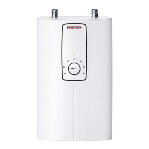
Steibel Eltron
Steibel Eltron DCE 11/13 Instruction Manual
Steibel Eltron
Steibel Eltron DHF 15C User manual
Steibel Eltron
Steibel Eltron TEMPRA Specification sheet
Steibel Eltron
Steibel Eltron PSH 120 i Operation manual
Steibel Eltron
Steibel Eltron UFP 5 h Instruction Manual
Popular Water Heater manuals by other brands
Helios
Helios AIR1 Series Installation and operating instructions

Epoca
Epoca 25-29 NB Installation and maintenance manual
Truma
Truma Therme operating instructions

Bradford White
Bradford White LG2PV50H653N manual

COTSWOLD
COTSWOLD DAIRY WATER HEATER instructions
Baxi
Baxi SPC SPLIT Installation and service manual


