Wintex Agro WINTEX 1000 User manual

P A G E | 1
Wintex Agro, Vilhelmsborgvej 15, DK-7700 Thisted
+45 97990800, contact@wintexagro.com, www.wintexagro.com
INSTRUCTION MANUAL WINTEX 1000
0-25 cm
Fully automatic
Fast and efficient
Optimum speed
Minimum maintenance
Reliable
Competitive
INTEGRATED HYDRAULICS
201605

P A G E | 2
Wintex Agro, Vilhelmsborgvej 15, DK-7700 Thisted
+45 97990800, contact@wintexagro.com, www.wintexagro.com
Manufactured by: WINTEX AGRO
Vilhelmsborgvej 15
DK-7700 Thisted
Type designation: WINTEX 1000
Voltage: 12 volt DC
Year of production: 2016
FOR YOUR SAFETY
Before starting the WINTEX1000 please make sure that nobody is present within a range of 10 meters.
Be seated correctly on the ATV with one leg on each side of the seat, and the hands placed correctly on the steering wheel.
When inspecting the WINTEX 1000, you must always activate the emergency stop, and the ATV must be turned off.
Every time you start the WINTEX 1000, you must test the emergency stop. If the emergency stop does not turnoff the soil sampler, you
must not use it.

P A G E | 3
Wintex Agro, Vilhelmsborgvej 15, DK-7700 Thisted
+45 97990800, contact@wintexagro.com, www.wintexagro.com
1. STARTING THE WINTEX 1000
Start the ATV, and deactivate the emergency stop. The red button must be up.
Activate the foot switch and the brake handle on the steering wheel, and shortly push the button
at your right hand. Foot switch and brake lever must be activated during the entire process. If
one of these switches is released, the process will stop.
Note: The emergency stop must always be activated at long stops, or the battery might be
discharged.
The WINTEX 1000 has three programs.
Program 1: The soil sampler’s standard program.
Program 2: The probe conducts an extra rotation.
Program 3: The probe moves up and down without rotation.
2. INTERRUPTING THE PROCESS
Due to various reasons it might be necessary to interrupt the process. In this case deactivate the foot
switch, and the process will stop immediately. When reactivating the foot switch and the brake handle
at the same time, the probe will go back into start position.
3. REPLACEMENT OF PROBE
The emergency stop must be activated, and the ATV must be turned off.
Use two 27 mm keys to loosen the probe.
The probe is mounted correctly when the slit of the probe points towards the soil box when the rotation
stops.

P A G E | 4
Wintex Agro, Vilhelmsborgvej 15, DK-7700 Thisted
+45 97990800, contact@wintexagro.com, www.wintexagro.com
4. ADJUSTMENT OF PROBE DEPTH
The probe can penetrate soil up to 25 cm. To adjust the depth, loosen the star knobs and move the
sensor up or down.
If further adjustment is necessary, the yellow unit can be moved in the holes of the mounting frame.
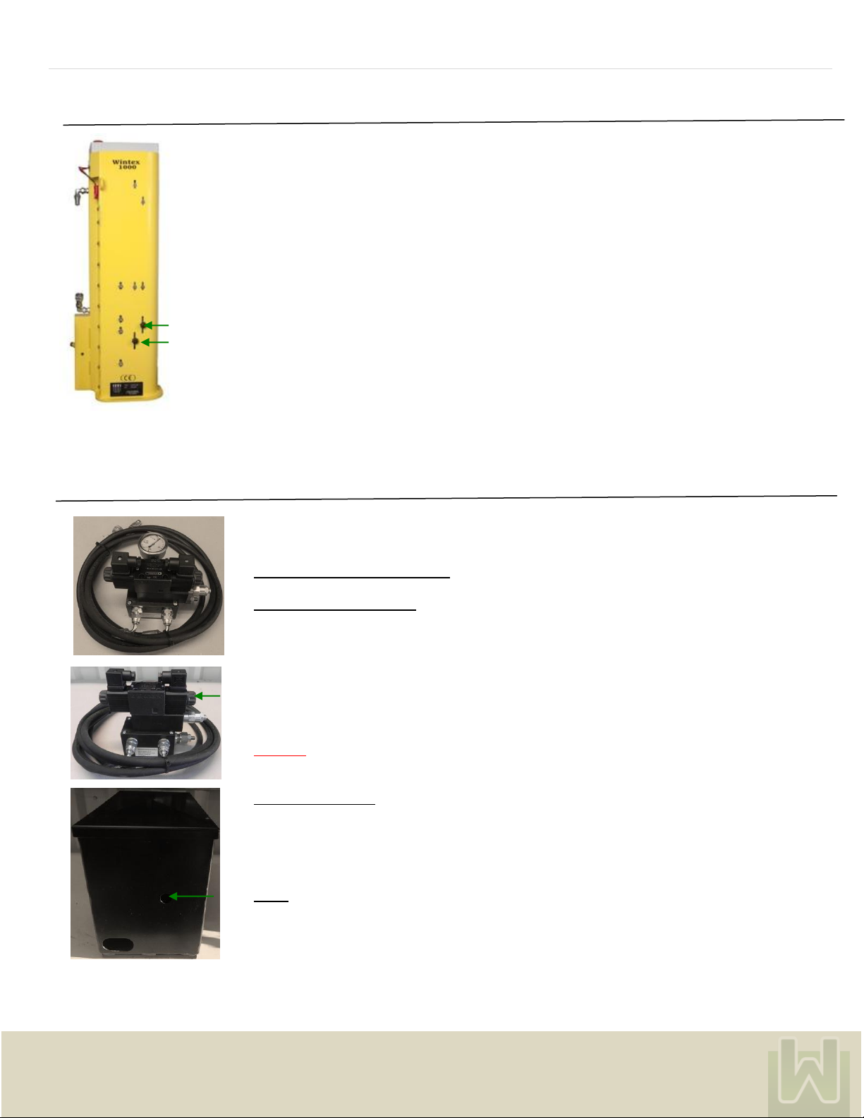
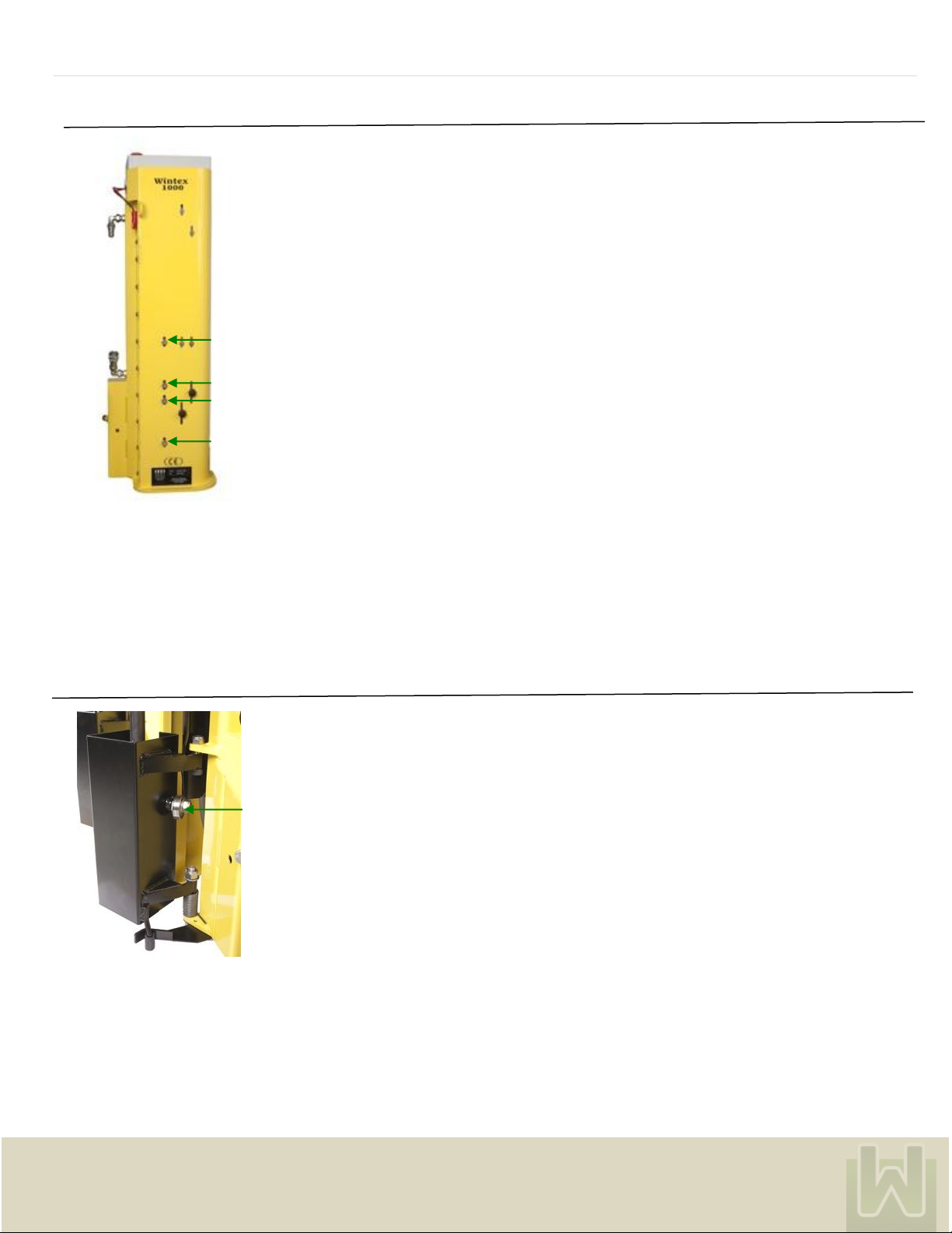
5. ADJUSTMENT OF OIL PRESSURE
The oil pressure is pre-set at a lower limit of 50 bar and an upper limit of 80 bar. Adjusting
the excess pressure valve can alter the pressure.
For adjusting the pressure downwards loosen the lock nut with a 19 mm key, and adjust the screw
with a 6 mm Allen key. Increase the pressure by turning the screw clockwise.
To adjust the pressure upwards loosen the locknut with a 17 mm key, and adjust the screw with a
5 mm Allen key. Increase the pressure by turning the screw clockwise.
Read the pressure directly on the mounted pressure gauge.
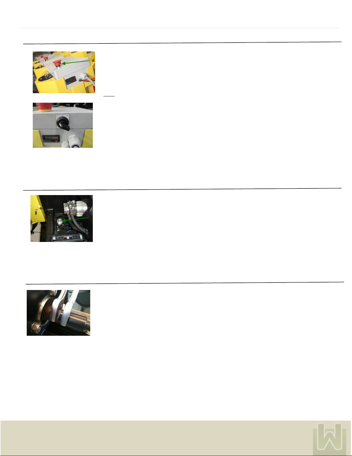
The soil sampler can also be activated manually. Push the rubber button (see arrow) in the hole at
the front of the oil tank, and the probe will move up. Push the button on the opposite side (see
arrow), and the probe will go down.
Important:
The lower pressure must not exceed 50 bar or the soil sampler will be damaged!
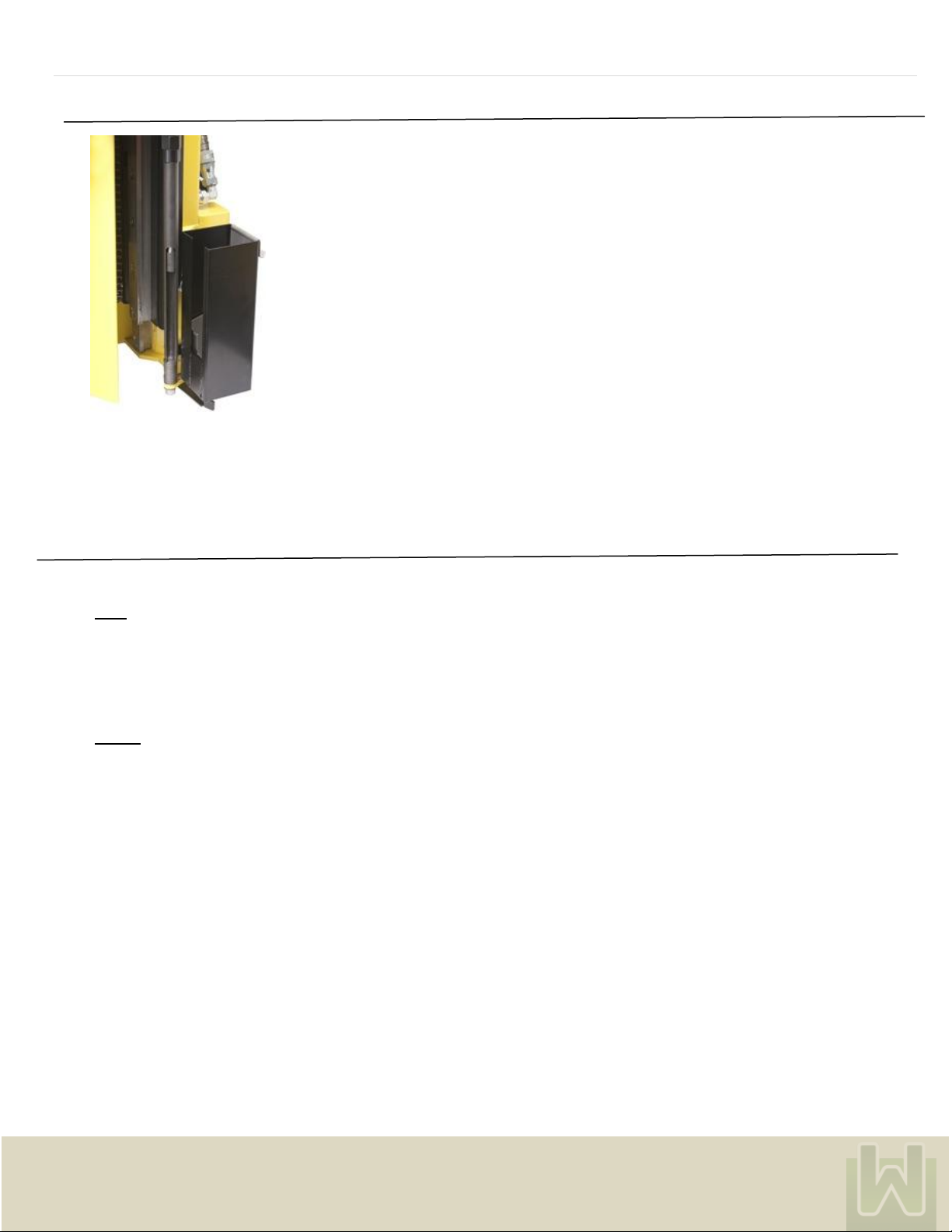
Filling with hydraulic oil:
Remove the screw lid at the top of the oil tank and replenish with hydraulic oil.
Important: Do only use DIN HLP 22 or 32 oil! The WINTEX 1000 is pre-filled with Equivis ZS32
hydraulic oil.
Fuses:
There are two fuses in the control box: one 25 amp fuse for the rotation of the probe (on the latest
models a 15 amp fuse) and one 7.5 amp fuse for current control.

P A G E | 5
Wintex Agro, Vilhelmsborgvej 15, DK-7700 Thisted
+45 97990800, contact@wintexagro.com, www.wintexagro.com
6. TIGHTENING AND ADJUSTMENT OF CHAIN
Make sure that the probe is up.
Loosen the four 8 mm bolts at the front of the WINTEX 1000 with a 6 mm Allen key.
Push the two upper 8 mm bolts down until the upper half of the chain is taut. Then tighten the
bolts.
Now push the lower 8 mm bolts up until the lower half of the chain is taut. This can be done
by by squeezing around the bolts with tongs. Then tighten the bolts.
Make sure that the chain is taut now.
7. ADJUSTMENT OF SOIL BOX
Adjust the soil box so that it is perpendicular with the soil sampler and so that the drilling head can
pass.
Adjust the soil box by loosening the nut and by turning the eccentric with the Wintex special key.

P A G E | 6
Wintex Agro, Vilhelmsborgvej 15, DK-7700 Thisted
+45 97990800, contact@wintexagro.com, www.wintexagro.com
8. ADJUSTMENT OF EJECTOR
When adjusting the ejector make sure to stop the probe approximately 10 cm from the start
position. Turn off the WINTEX 1000, and activate the emergency stop.
Loosen the six Allen screws (three at the top and three below). Then loosen the nut for the probe.
Adjust the ejector so that it is placed in the middle of the hole of the probe.
Tighten the screws and the nut again, and the probe will move back into start position. If necessary
adjust the ejector by slightly bending it when it is free from the probe tube.
9. MAINTENANCE
Important: After the first eight hours of operation, screws, bolts and nuts must be tightened.
Daily:
- Lubricate chain with oil spray. Avoid the oil to get in touch with the aluminium rails.
- Lubricate the hinges of the soil box.
- Clean the ejector.
- Clean the chain for the rotation of the probe (is easily carried out with compressed air).
- Clean the parts where soil can be accumulated.
Weekly:
- Check and tighten vital parts.
- Check and if necessary change the ejector tip.
- Check and if necessary change the probe.
- Check the oil level of the hydraulics.

P A G E | 7
Wintex Agro, Vilhelmsborgvej 15, DK-7700 Thisted
+45 97990800, contact@wintexagro.com, www.wintexagro.com
10. PROBLEM SOLVING
PROBLEM
CAUSE
POSSIBLE SOLUTIONS
The WINTEX 1000 does not start.
1) The fuse is blown.
2) The emergency stop is activated.
3) Does not activate all switches.
4) A switch is defect.
5) There is a lack of power supply.
1) Put in a new fuse.
2) Deactivate the emergency stop.
3) See manual point 1.
4) Change the switch.
5) Charge the battery.
The probe does not rotate.
1) The fuse is blown.
2) The chain is broken.
1) Put in a new fuse.
2) Replace the chain.
The soil cannot be squeezed out of the
probe.
1) The ejector tip is worn.
2) The probe is choked up with soil.
3) The probe is bent.
4) The ejector is bent.
1) Change the ejector tip.
2) Clean the probe for soil.
3) Exchange the probe (manual point 3).
4) Adjust the ejector (manual point 8)
The ATV is being lifted when the probe
goes into the ground.
1) The oil pressure is too high.
1) Reduce the oil pressure.
The ejector cannot pass through the
probe tube.
1) The ejector is stuck.
2) The chain is dislocated.
3) The soil sampler’s movement is
blocked by soil.
1) Adjust the ejector (manual point 8).
2) Adjust and tighten the chain (manual point 6).
3) Clean the soil sampler.
The probe does not stop spinning.
1) The sensor is not adjusted correctly.
2) The sensor not adjusted correctly.
3) A wire fell out of the sensor in the
drilling head or the middle sensor.
4) The wires which are going to the
computer are disconnected.
1) Move the middle sensor in the tower closer to
the drilling head or replace it.
2) Move the sensor in the drilling head closer to
the funnel or replace it.
3) Re-connect the wire.
4) Re-connect the wires (I4 or I6).
The drilling head will go down, but would not
come up.
1) The sensor not adjusted correctly or
the sensor is broken.
2) The hydraulic pressure on the
Honda motor is too low.
3) Bad connection to the Honda
Motor.
4) A nut fell off between the hydraulic
cylinder and slide for the soil box.
5) Broken computer.
6) The wires are disconnected from
the computer (Q2 or Q3).
7) The battery of the ATV is weak
and is not sending the full 12 volts.
1) Move the bottom sensor closer to the drilling
head, or replace the bottom sensor.
2) Adjust the pressure.
3) Check the connection to the Honda motor.
4) Re-place the nut.
5) Install a new computer.
6) Re-connect the wires.
7) Recharge or change the battery.
The drilling head hits the soil box.
1) Adjust the bucket bearing.

P A G E | 8
Wintex Agro, Vilhelmsborgvej 15, DK-7700 Thisted
+45 97990800, contact@wintexagro.com, www.wintexagro.com
The drilling head will not move down or up.
1) There is not enough power to the
tower (12 volts needed).
2) One of the three sensors is
broken or disconnected.
3) A fuse is blown.
4) The emergency stop is activated.
5) The hydraulic pressure of the
Honda motor is too low.
6) A wire for the computer is
disconnected.
7) The bottom sensor is broken.
8) The grey plug is not plugged in.
1) Recharge or change the battery.
2) Replace or change the sensor.
3) Set in a new fuse.
4) Deactivate the emergency stop.
5) Adjust the pressure.
6) Re-connect the wire.
7) Exchange the bottom sensor.
8) Plug in the grey plug.
The probe gets stuck when going up or down.
1) Dirt is stuck behind the ejector tip.
2) The probe is bent.
3) The chain is too loose and came
off the sprocket.
1) Remove the dirt.
2) Set in a new probe.
3) Set the chain back on the sprocket and tighten
it.
The drilling head will not stop when coming
up.
1) There is a broken top or middle
sensor.
2) The wire going to the sensor in the
drilling head came loose.
3) The wire going to the computer
Came loose.
1) Replace the broken sensor.
2) Tighten the wire.
3) Tighten the wire (I4 or I6).
The probe ejects the sample onto the ground.
1) The chain in the drilling head
came loose.
2) The probe is no longer aligned
correctly.
3) The sensor is not adjusted
correctly.
4) The sensor is not adjusted
correctly.
1) Tighten the chain.
2) Re-align the probe to eject the soil into the
soil box.
3) Move the sensor in the drilling head closer to
the funnel or replace it.
4) Move the middle sensor in the tower closer to
the drilling head or replace it.
The drilling head has a lot of horizontal
play.
1) The screws holding the wearing
plates came loose.
2) The wearing plates are worn.
1) Tighten the screws.
2) Replace the wearing plates.
For testing the brake contact, the start switch and the foot switch just activate the ignition on the vehicle, but do not start the
motor. If all switches work, the rotation will start. It the rotation does not start, there is an error in one of the switches.
Other manuals for WINTEX 1000
2
Table of contents
Other Wintex Agro Farm Equipment manuals