STEIN EMILIO User manual

THIS PRODUCT REQUIRES
2 PACKAGES FOR INSTALLATION
EMILIO SHOWER UNIT
ACRYLIC AND TILE
INSTALLATION INSTRUCTIONS
2015 / V4

1EMILIO SHOWER UNIT Acrylic and Tile - Installation Instructions
EMILIO SHOWER UNIT
ACRYLIC AND TILE
INSTALLATION INSTRUCTIONS
PLEASE READ CAREFULLY
GENERAL INFORMATION
Thank you for choosing Stein Bathroomware. When you receive your Emilio Shower packages please
check for any damage. If damage has occurred advise your supplier immediately and do not
proceed with installation. Damage reported after installation will not be accepted.
DISCLAIMER
Stein International Ltd are not liable for any Emilio Shower that has not been installed correctly.
INSTALLATION NOTES
• All silicone bonding: We recommend translucent Bostik V60 (available to purchase from your
retailer).
• All layout measurements assume the oor is level, the walls are plumb and all surfaces at. Any
variations must be adjusted in the measurements provided.
• Toughened safety glass cannot be reworked. Do Not try to alter parts in any way.
PREPARATION
• The walls must be plumb with internal corner being at 90 degrees. Solid xing must be provided in
the walls behind the wall channels and behind the wall mounted rail bracket shown in the Layout
Plan Diagram 1.1.
SAFETY GUIDE
• This product is heavy and may require two people to install.
• Always stand glass up after unpacking the components and use soft packing where in contact with
hard surfaces. Take care not to strike an edge or corner on a hard surface.
• Special care should be taken when drilling walls to avoid hidden pipes or electrical cables.
• Wear protective gloves and eye protection.
WE RECOMMEND THAT A PROFESSIONAL SHOWER INSTALLER IS USED FOR
INSTALLATION OF THIS PRODUCT TO ENSURE THE VERY BEST OUTCOME

2EMILIO SHOWER UNIT Acrylic and Tile - Installation Instructions
EMILIO SHOWER
COMPLETED INSTALLATION DIAGRAM
TOOLS & MATERIALS REQUIRED (NOT SUPPLIED)
• Soft pencil and masking tape
• Spirit level and large square.
• Rags and white spirits
• Square head screwdriver
• Tape measure
• Drill
• 6mm masonry drill bit
• 3mm masonry drill bit
• NG Sika Silaex cartridge and gun
WE RECOMMEND THAT A PROFESSIONAL SHOWER INSTALLER IS USED FOR
INSTALLATION OF THIS PRODUCT TO ENSURE THE VERY BEST OUTCOME

3EMILIO SHOWER UNIT Acrylic and Tile - Installation Instructions
EMILIO SHOWER - SELECTING THE CORRECT LAYOUT PLAN
There are four layout pages provided. Please ensure you select the correct layout page and combine
this with the installation details.
Emilio Shower - 2 Sided Acrylic ....................................................... Layout Plan A ... Page 4
Emilio Shower - 2 Sided Tile with Ezi-Lay Tile Tray.......................... Layout Plan B ... Page 5
Emilio Shower - Alcove (Door Only) ............................................... Layout Plan C ... Page 6
Emilio Shower - All other applications............................................ Layout Plan D ... Page 7
checked
checked
checked
checked
checked
checked
checked
Solid xing must be provided in the walls behind the wall channels. Refer to the correct
Layout Plan to establish your shower type.
To ensure a successful result the walls must be plumb and the oor at and level.
Contract a plumber to ensure waste tting is correctly installed.
To install acrylic tray and liner, please refer to separate installation instructions with packaged
with the product.
To install Ezi-Lay Tile Tray please refer to separate installation instructions provided checked
with the packaged product.
Wall and oor surfaces must be waterproofed by a Certied Applicator and a Producer
Statement provided for the local council.
All tiling must be completed and allowed to cure before installing the shower enclosure.
PREPARATION CHECKLIST
THE FOLLOWING ITEMS MUST BE COMPLETED PRIOR TO INSTALLATION
ACRYLIC INSTALLATIONS OPTION
TILE INSTALLATIONS OPTION

4EMILIO SHOWER UNIT Acrylic and Tile - Installation Instructions
EMILIO SHOWER: ACRYLIC 2 SIDED - LAYOUT PLAN A
OPTION A: EMILIO ACRYLIC SHOWER (Applies to 1200 x 900 and 1500 x 1000 sizes)
Emilio Acrylic Shower with Stein Acrylic Tray and ABS/Acrylic Liner:
Set out the Emilio Shower by marking out the outside line of the wall channels (A) 12mm in from the
outside edge of the tray. This will allow for suitable placement of the shower plus some variances from
plumb on the walls. Greater variances will need to be calculated in the layout.
NOTE: All measurements assume the oor is level, the walls are plumb and all surfaces are at. Any
variation must be adjusted for in the measurements provided.
DOTTED LINE:
OUTER CHANNEL BOUNDARY LINE
GLASS LINE:
5MM BACK FROM DOTTED LINE
A
A

5EMILIO SHOWER UNIT Acrylic and Tile - Installation Instructions
EMILIO SHOWER: TILE WITH EZI-LAY TILE TRAY - LAYOUT PLAN B
OPTION B: EMILIO TILE SHOWER WITH STANDARD EZI-LAY TILE TRAY
Emilio Tile Shower with Ezi-Lay Tile Tray with Hobs Application:
Set out the Emilio Shower place by marking out the outside line of the Wall channels (A) 30mm in
from the outside edge of the tiled hob. This will allow for suitable placement of the shower plus some
variances from plumb on the walls. Greater variances will need to be calculated in the layout.
DOTTED LINE:
OUTER CHANNEL BOUNDARY LINE
GLASS LINE:
5MM BACK FROM DOTTED LINE
A
A
NOTE: All measurements assume the oor is level, the walls are plumb and all surfaces are at. Any
variation must be adjusted for in the measurements provided.
NOTE: When installing the Emilio Frameless Shower on to a tiled wall some local authorities do not
allow wall channels to be xed by screwing through tiles. In this instance use BOSTIK V60 to x the
wall channels to the tiles. You must leave the wall channel to set for the minimum time required as
instructed on the BOSTIK cartridge before installing glass.

6EMILIO SHOWER UNIT Acrylic and Tile - Installation Instructions
EMILIO ALCOVE (DOOR ONLY) - LAYOUT PLAN C
NOTE: All measurements assume the oor is level, the walls are plumb
and all surfaces are at. Any variation must be adjusted for in the
measurements provided.
PLEASE NOTE: When installing the Emilio Frameless Shower on to a tiled wall some local authorities do not allow wall channels to be
xed by screwing through tiles. In this instance use BOSTIK V60 to x the wall channels to the tiles. You must leave the wall channel to set
for the minimum time required as instructed on the BOSTIK cartridge before installing glass.
This is a brief overview of how to set up a door assembly only. This runs in conjunction with the general
instruction sheet.
Step 1 Establish an outer boundary line across the base and up each wall (use the ‘Shower Line to
Tray Edge’ Table above).
Step 2 On the side of the xed glass fasten the wall channel (1) (Refer Items 1.1 and 1.2, Page 9)
Step 3 Place front xed glass panel in position (21) (Refer item 2, Page 9).
Step 4 Fix the wall mounted bracket (14) in position as detail (3.2 - A1 detail, Page 10).
Next Step To replicate the mounting point on the opposite side for the Rail.
A: Measure the installed rail bracket position back from the outer boundary line.
B: Measure the height from the base to rail bracket.
C: Mark A and B on opposite side. Hold the bracket on the marked wall with the rail in place on both sides and
double check that the rail is level or adjust as required.
E: Place the wall bracket in position and mark two holes on the wall. Pre-drill the wall and fasten in position.
F: Place the rail in position and with front glass and attach this (8). Refer items (2, 3.3 detail C).
All other installation steps can be now followed in the general instructions eliminating the return panel
details that do not apply.
OPTION C: EMILIO ALCOVE (DOOR ONLY) - APPLIES
TO 1200 AND 1500 SIZES WITH TILE BASE AND ACRYLIC
BASE APPLICATIONS
The following table covers the Door Size with the
Minimum and Maximum Range. Care must be taken
if using the minimum or maximum measurements as
discrepancies in the walls or base may not allow for this.
SHOWER DOOR TYPE FRONT DOOR PANEL MIN/MAX
1200 Door 1165 - 1180mm
1500 Door 1465 - 1480mm
SHOWER LINE TO TRAY EDGE
Acrylic Tray 12mm
Ezi-Lay Tile Tray 30mm
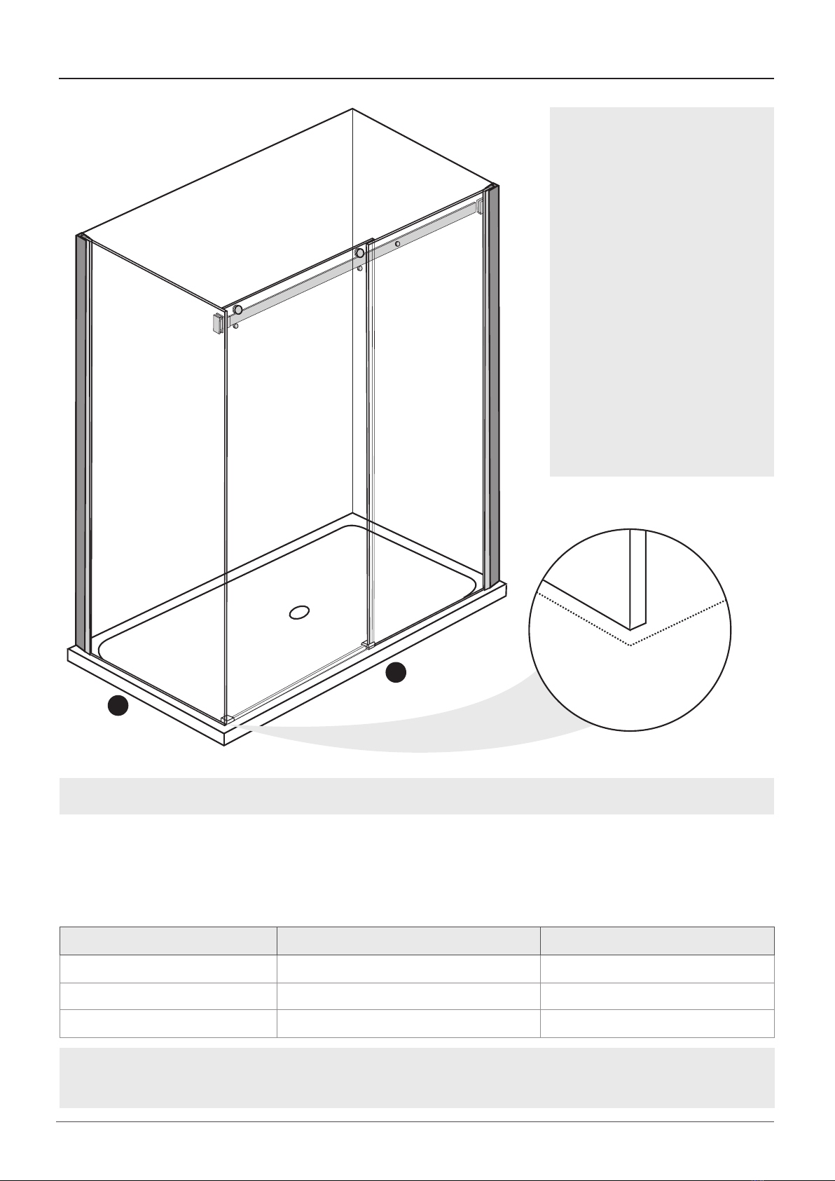
Height
Depth
Dotted Line:
Outer boundary
Shower Line to Tray Edge
(See Table)
Rail Brackets:
Mounted on both
L/H and R/H

7EMILIO SHOWER UNIT Acrylic and Tile - Installation Instructions
EMILIO SHOWER: ALL OTHER APPLICATIONS - LAYOUT PLAN D
OPTION D: EMILIO SHOWER - ALL OTHER APPLICATIONS AND SIZE RANGES
Emilio Shower - All other Tile Bases or Entry Level Applications:
A and B measurements are the range that can be used for the outer boundary lines for the
wall channels. Care must be taken if using either the minimum or maximum measurements as
discrepancies in the walls or oor may not allow for this.
DOTTED LINE:
OUTER CHANNEL BOUNDARY LINE
GLASS LINE:
5MM BACK FROM DOTTED LINE
A
B
NOTE: All measurements assume the oor is level, the walls are plumb and all surfaces are at. Any
variation must be adjusted for in the measurements provided.
PLEASE NOTE:
When installing the Emilio
Frameless Shower on to
a tiled wall some local
authorities do not allow
wall channels to be xed
by screwing through tiles.
In this instance use BOSTIK
V60 to x the wall channels
to the tiles. You must leave
the wall channel to set for
the minimum time required
as instructed on the
BOSTIK cartridge before
installing glass.
SHOWER TYPE FRONT DOOR PANEL (A) MIN/MAX RETURN PANEL (B) MIN/MAX
1200 x 900 1165 - 1180mm 865 - 880mm
1500 x 900 1465 - 1480mm 865 - 880mm
1500 x 1000 1465 - 1480mm 965 - 980mm

8EMILIO SHOWER UNIT Acrylic and Tile - Installation Instructions
REF DESCRIPTION PART NO. QTY REF DESCRIPTION PART NO. QTY
1Wall channels PAR1044 2 14 Rail mounting brackets LH: PAR1038
RH: PAR1039 2
2Return panel 1 15 Mounting bracket covers PAR1044 2
3Door panel 1 16 Screw cover caps PAR1036 8
4Buffer strips PAR1028 2 17 Wall plate gaskets PAR1043 2
5Buffer seal PAR1029 2 18 Return panel xing plate PAR1043 1
6Handle set PAR1037 1 19 Screws M4 x 35 PAR1036 8
7Lock in knob sets PAR1041 2 21 Screws M4 x 8 PAR1036 8
8Front glass xing PAR1042 1 22 Front xed panel 1
9End blocks (L/R) LH: PAR1032
RH: PAR1033 2 23 Allen wrench 1
10 Sliding blocks (L/R) LH: PAR1034
RH: PAR1035 2 24 Wrench 1
11 Water bar PAR1031 1 25 Screws M5 x 10 PAR1043 2
12 Roller sets PAR1040 2
13 Rail PAR1030 1
EMILIO SHOWER UNIT
ASSEMBLY DIAGRAM

9EMILIO SHOWER UNIT Acrylic and Tile - Installation Instructions
1.1 1.2
EMILIO SHOWER - INSTALLATION INSTRUCTIONS
Identify the specic Layout Plan applicable to your specic shower. Use the correct Layout
Plan in conjunction with the installation instructions. Mark out the wall channels taking
into account the guidance notes.
1.1
1.2
2
Pre-drill lead holes in the wall lining matching up to the Channel holes.
TILING NOTE: If it is a tiling option re-drill holes in the channel to line up with the grout lines and
pre-drill the tile at this point. In some instances a diamond drill bit may be needed.
Apply silicone to the back of the channel and x in place with the M4 x 35 screws ensuring that
the channel remains plumb.
Insert the return panel (2) and xed front panel (22) into the wall channels (1).
TILING NOTE: Place 10mm wide thin clear plastic strips as isolation packers at 90 degrees under
the xed glass. Finally before nishing with silicone, trim the excess with a knife.

10EMILIO SHOWER UNIT Acrylic and Tile - Installation Instructions
NOTE: This screw should
face the inside of the shower.
Allow a 5mm gap
between channel
and bracket without the
outer cover.
Front glass xing.
Fit covers onto
both end brackets
Fit rail into both
end brackets
Rail Bracket
Covers
38MM
WALL MOUNTED RAIL
BRACKET POSITION
3.2
3.3
A1
Install rail brackets (14,17 & 18) to return panel.
On the wall mark position of the rail mounting bracket (14) 38mm down from the top of the
glass and 5mm out from the wall channel (Diagram A1). Place the rail (13) into the bracket at
return panel and hold up the rail with the wall bracket (14) to marks. Check for level, if needed
adjust height of rail mounting bracket at the wall and then x bracket in place.
Insert rail (13) complete with LH and RH mounting bracket covers (15). Install front glass xing
(8). Plumb the return panel, tighten the rail bracket allen keys and slide the covers in place.
ENSURE A PLASTIC GLASS PROTECTOR IS USED BETWEEN ALL METAL PARTS AND THE GLASS
3.1
3.2
3.3
3.1
B

11EMILIO SHOWER UNIT Acrylic and Tile - Installation Instructions
4.5
4.1
4.2
4.3
4.4
A
A
A
B1
A1
B
4.1
4.2
4.3
4.4
4.5
Install the roller sets (12) to door panel (3). Rollers should be on the outside of the door.
Hang the door on the rail from inside of the shower.
Carefully slide the door toward the return panel and check the gap between door and return panel
is even. Adjust if necessary using offset in rollers or adjustment from the rail support.
Bond the following parts to the tray with NG Sikaex Silicone. Sliding block (10) slotted into the
glass front panel edge and the waterbar (11) positioned parallel to the outside edge of the tray
going across to the end block (9) against the return panel. Tape in position with duct tape and
allow 24 hours for this to cure.
Install lock in knobs on the door & tighten rail xings.
4.4 B1
END BLOCK WATER
BAR - SLIDING BLOCK
ASSEMBLY

12EMILIO SHOWER UNIT Acrylic and Tile - Installation Instructions
5.1
5.2
5.3
5.4
Plumb the ends of the glass. On the inside of shower drill 3.2mm holes through both the xed
panel proles and into the wall channels (NOTE: Ensure that the chosen position avoids drilling
through the glass - see Diagram 5.1). Screw together using M4 Screws (21). Cover the screws with
screw cover caps (22).
Install buffer strips (4) onto the door panel.
Install vertical buffer seal (5) onto the xed panel.
Install the handle set (6) with the locking screws on the inside of the shower.
FIXED GLASS PANEL
FIXED PANEL
PROFILE
ENSURE GLASS PANELS
REMAIN LEVEL DURING
INSTALLATION PROCESS
CHANNEL WALL
5.1
5.2
5.3
5.4

13
Apply high quality neutral cure silicone to the outside.
DO NOT USE SHOWER FOR 24 HOURS
24 HOURS
6
Silicone is not used on the inside of the shower screen because water can build up over time
within the wall channel and leak out of the shower area. The screen is designed to allow the
water to return into the shower area, if any is present. SCREENS THAT ARE SEALED ON
THE INSIDE WILL VOID WARRANTY.
113 Newton Street, Mount Maunganui
Freephone 0800 002 299
Phone +64 7 928 9990
www.stein.co.nz
Table of contents
Other STEIN Bathroom Fixture manuals

STEIN
STEIN GEORGIA User manual

STEIN
STEIN WINDSOR SHOWER UNIT SQUARE & ALCOVE Installation guide

STEIN
STEIN TURTLE SHELL User manual

STEIN
STEIN EASYCLEAN WASTE User manual

STEIN
STEIN VIDA User manual

STEIN
STEIN TURTLE SHELL User manual

STEIN
STEIN CURVED ACRYLIC User manual

STEIN
STEIN Georgia Acrylic User manual

STEIN
STEIN PROJECT User manual

STEIN
STEIN STE1218 User manual
Popular Bathroom Fixture manuals by other brands

Jysk
Jysk HANNA 706-16-1008 manual

Steinbach
Steinbach Flexible 049010 ORIGINAL OWNER'S MANUAL

Akuaplus
Akuaplus RB6116 ELENA instruction manual

Pfister
Pfister Designer F-048-DE Quick installation guide

GoodHome
GoodHome cicely 3663602643319 Assembly instructions

Jacuzzi
Jacuzzi BY82000 Installation and operating instructions