manuals.online logo
Brands
  1. Home
  2. •
  3. Brands
  4. •
  5. Stelpro
  6. •
  7. Fan
  8. •
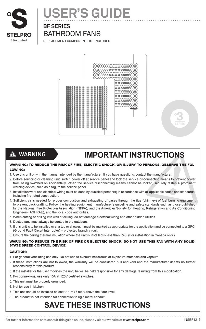
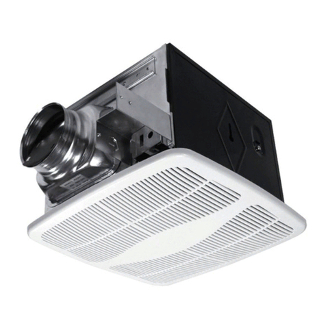
  9. Stelpro BFQ Series User guide

Stelpro BFQ Series User guide

INSBFQ0213
STELPRO DESIGN INC. | Saint-Bruno-de-Montarville | Québec | J3V 6L7
FRONTSIDE SIDE
TOP
8 9/16''
218mm
8 9/16''
218mm
3 3/4''
96mm
1 7/16''
36mm
3/4''
18mm
O7/8''
22mm
KOE
2 1/8''
54mm
11/16''
17mm
O7/8''
22mm
KOE DUCT ADAPTOR
O4'' [101.6mm]
12''
305mm
12''
305mm
12''
305mm
12 1/2''
318mm
3 1/2''
88mm
BFQ GRILL BFQL(X) GRILL
5''
127mm
1 1/2''
39mm
#DIAGRAM #PART DESCRIPTION
1 SA-BFQ-0007 MOTOR PLATE FOR BFQ SUB ASSEMBLY
2 MO-061 MOTOR 44W 1 SPEED 120V 60HZ CCW (WITH 3 PINS CONNECTOR)
2 MO-061-1 MOTOR 32W 1 SPEED 120V 60HZ CCW (WITH 3 PINS CONNECTOR)
3 P-BFQ80Z0 BFQ IMPELLER
4 P-BFQ00B0 4 INCH BFQ OUTLET & DAMPER ASSEMBLED
5 CAP-XXX ASK YOUR STELPRO REP FOR PART NUMBER
6 HAR-020 HARNESS, BFQL CUSTOMER INTERFACE
6 HAR-022 HARNESS, BFQ CUSTOMER INTERFACE
7 SA-BFSQ-0001 SUB ASSEMBLY OF THE GRILLE WITHOUT LIGHT
8 SA-BFQL-0001 SUB ASSEMBLY OF THE GRILLE WITH LIGHT FOR GU24 LIGHT
8 SA-BFQL-0002 SUB ASSEMBLY OF THE GRILLE WITH LIGHT FOR A19 BULB
9 FLL-001 FLUORESCENT LIGHTBULB SPIRAL 23W SOFT WITH GU24 BASE
10 INL-001 LIGHTBULB A19 75W INCANDESCENT E26 BASE
8
7
2
3
4
5
1
10
9
6
installer/user’s Guide
BFQ & BFQl series
BAThRoom fAN
READ AND SAVE THESE INSTRUCTIONS.
WARNING: TO REDUCE THE RISK OF FIRE, ELECTRIC SHOCK, OR INJURY TO PERSONS, OBSERVE THE FOLLOWING:
1. Use this unit only in the manner intended by the manufacturer. If you have questions, contact the manufacturer.
2. Before servicing or cleaning unit, switch power off at service panel and lock the service disconnecting means to prevent power from being switched on accidentally.
When the service disconnecting means cannot be locked, securely fasten a prominent warning device, such as a tag, to the service panel.
3. Installation work and electrical wiring must be done by qualied person(s) in accordance with all applicable codes and standards, including re-rated construction.
4. Sufcient air is needed for proper combustion and exhausting of gases through the ue (chimney) of fuel burning equipment to prevent back drafting. Follow the heat-
ing equipment manufacturer’s guideline and safety standards such as those published by the National Fire Protection Association (NFPA), and the American Society
for Heating, Refrigeration and Air Conditioning Engineers (ASHRAE), and the local code authorities.
5. When cutting or drilling into wall or ceiling, do not damage electrical wiring and other hidden utilities.
6. Ducted fans must always be vented to the outdoors.
7. If this unit is to be installed over a tub or shower, it must be marked as appropriate for the application and be connected to a GFCI (Ground Fault Circuit Interrupter)
– protected branch circuit.
8. Ensure the ceiling thermal insulation where the unit is installed is less than R40. (For installation in Canada only.)
WARNING: TO REDUCE THE RISK OF FIRE OR ELECTRIC SHOCK, DO NOT USE THIS FAN WITH ANY SOLID-STATE SPEED
CONTROL DEVICE.
CAUTION:
1. For general ventilating use only. Do not use to exhaust hazardous or explosive materials and vapours.
2. If these instructions are not followed, the warranty will be considered null and void and the manufacturer deems no further responsibility for this product.
3. If the installer or the user modies the unit, he will be held responsible for any damage resulting from this modication.
4. For connexions, use only 15A @ 120V certied switches.
5. This unit must be properly grounded.
6. Not for use in kitchen.
7. This unit is for ceiling installation only.
WarninG
TEchNIcAL DRAWINg AND REpLAcEmENT compoNENT LIST
INSTALLATION SUR
SOLIVE /
ON JOIST
INSTALLATION
INSTALLATION SUR
POUTRELLE EN I /
ON I-BEAM
INSTALLATION
OU / OR
INSTALLATION EN
RÉNOVATION /
RETROFIT
INSTALLATION
PLAN DE FILAGE / WIRING DIAGRAM CONDUITS / DUCTS
PIÈCES
NÉCESSAIRES /
PARTS NEEDED
PIÈCES
NÉCESSAIRES /
PARTS NEEDED
PIÈCES
NÉCESSAIRES /
PARTS NEEDED
INSTALLATION DE LA PLAQUE DU
MOTEUR/
MOTOR PLATE INSTALLATION
DÉMONTER DANS L'ORDRE INVERSE /
DISASSEMBLE INREVERSE ORDER
DÉMONTER DANS L'ORDRE INVERSE /
DISASSEMBLE INREVERSE ORDER
DÉMONTER DANS L'ORDRE INVERSE /
DISASSEMBLE INREVERSE ORDER
BREVETS EN INSTANCE / PATENTS PENDING
INSTALLATION DE LA PLAQUE DU
MOTEUR/
MOTOR PLATE INSTALLATION
INSTALLATION DE LA PLAQUE DU
MOTEUR/
MOTOR PLATE INSTALLATION
LUMIÈRE / LIGHT
GRILLE / GRILL


















X 3 - 4
X 2
X 3 X 2
X 2
X 2
X 2
X 4
X 4
Installer les supports selon la dimension du gypse. /
Install the bracketsaccordingto the gypsum size.
Installer à /
1/2'' ou/ 5/8''
Appuyer le boîtier et les supports sur la solive. /
Press thecasingand the bracketsagainst the joist. Visser le boîtier sur la solive. /
Screw thecasing on the joist.
Visser /
X 3
Trous de vissage pour
mettre au niveau. /
Installer les supports selon la dimension du
gypse et visser les supports pour poutrelle en I. /
Install the brackets accordingto the gypsum
size andscrew the I-beam bracket.
Installer à /
1/2'' ou/ 5/8''
Appuyer le boîtier et les supports sur
la poutrelle. / Press thecasingand
the bracketsagainst the beam.
Support pour poutrelle en I. /
Visser le boîtier et les supports sur
la poutrelle en I. / Screw the
casingand the bracket onthe
I-beam.
Visser /
X 3
Vis pour mettre au niveau. /
Mettre au niveau à l'aide de
la vis des supports. / Level
with the bracket screw.
Installer le conduit et le filage électrique. /
Gabarit /
Ouverture dans le plafond. /
Découper une ouverture dans le
plafond de la même dimension
que le gabarit. / Cut an opening
in the ceiling ofthe same
dimensionas the template.
Insérer le boîtier dans le plafond et
installer les supports selon la dimension
du gypse. / Insertthe casing in the
ceilingand install the brackets
according tothe gypsumsize.
Installer à /
1/2'' ou/ 5/8'' Installer à /
1/2'' ou/ 5/8''
Appuyer le boîtier dans l'ouverture du plafond et installer les
supports pour rénovation selon la dimension du gypse. /
Press thecasing over the opening ofthe ceilingand
install the retro-fit bracketsaccording tothe gypsumsize.
Visser /
NON RECOMMANDÉ
NOT RECOMMENDED
[Bon / Good] : PVC ou Acier galvanisé /
PVC or Galvanized steel
[Moyen / Medium] : Flexible en aluminium /
Flexible aluminum
[Faible / Poor] : Vinyle / Vinyl
BON
GOOD
MEILLEUR
BEST
Pour gypse de 1/2'' et 5/8''. /
For 1/2''and5/8'' gypsum.
1 15/16''
Jusqu'à / Up to
Pièces incluses /
Parts supplied
Pièces incluses /
Parts supplied
Pièces incluses /
Parts supplied
Insérer le pli de la plaque
dans les 2 attaches du
boîtier. / Insert the flange
of the plate in the 2clips
of the casing.
Fermer la plaque
complètement. /
Close the plate
completely.
Visser la plaque et
connecter le moteur. /
Screw the plate and
connect the motor.
Pli /
Attache /
Vis /
Connecter /

NOIR Ventilateur alimentation /
BLACK power fan
BLEU Lumière /
BLUE Light
Vis VERTE Mise à la terre /
GREEN Ground screw
Boîte de jonction du ventilateur. / Fan junction box.
Boîtier d'interrupteur. / Switch box.
NOIR Vivant /
BLACK Live
BLANC Neutre /
WHITE Neutral
NU Mise à la terre /
BARE Ground
Option
ou/or
BFQL(I / F)
BLANC Neutre /WHITE Neutral
Ventilateur marche / Fan ON
Lumière / Light
BX-PROTBFQ REV01
Insérer le pli de la plaque
dans les 2 attaches du
boîtier. / Insert the flange
of the plate in the 2clips
of the casing.
Fermer la plaque
complètement. /
Close the plate
completely.
Visser la plaque et
connecter le moteur. /
Screw the plate and
connect the motor.
Pli /
Attache /
Vis /
Connecter /

GABARIT/ Découper le gabarit en suivant les lignes pointillées. / Cut the template by following the dotted line.


A


DETAIL A
Appuyer sur le côté du
globe de la lumière pour
démonter celui-ci. /
Push on the side ofthe
light cup to unclip it. A: LFC culot GU24 MAX23W / CFL
GU24 base 23W MAX.
B: Ampoule A19 MAX 100W. / Light bulb
A19 100W MAX.
AB
BFQLF BFQLI
Insérer les 2 attaches à ressort du boîtier dans
les ouvertures correspondantes de la grille et
pousser sur celle-ci. / Insert the2 spring clips of
the casing in the corresponding opening ofthe
grill and push on the grill.
Attache à ressort /
Ouverture /

or Install at
Screw holes for leveling.
Screw
Clip
Flange Connect
Screws
Clip
Flange Connect
Screws
or Install at
I-beambracket.
Screw Screw holes for leveling.
Installthe duct and the electricalwiring.
Ceiling opening.
Template
or Install at
or Install at
Screw
TEMPLATE
Clip
Flange Connect
Screws
Spring clipOpening
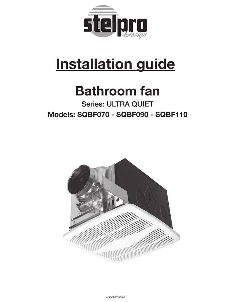
This manual suits for next models

1

Other Stelpro Fan manuals

Stelpro ULTRA QUIET Series User manual

Stelpro

Stelpro ULTRA QUIET Series User manual

Stelpro MUA Series User manual

Stelpro

Stelpro MUA Series User manual

Stelpro SBFHL070 User manual

Stelpro

Stelpro SBFHL070 User manual

Stelpro ULTRA SILENCIEUX Series User manual

Stelpro

Stelpro ULTRA SILENCIEUX Series User manual

Stelpro SBF050 User manual

Stelpro

Stelpro SBF050 User manual

Stelpro SQBF070 User manual

Stelpro

Stelpro SQBF070 User manual

Stelpro MAKE UP AIR MUAA Series User manual

Stelpro

Stelpro MAKE UP AIR MUAA Series User manual

Stelpro BFNHL User manual

Stelpro

Stelpro BFNHL User manual

Stelpro BF SERIES User manual

Stelpro

Stelpro BF SERIES User manual

Popular Fan manuals by other brands

Haier FTM348 RBPG - 10-04 user manual

Haier

Haier FTM348 RBPG - 10-04 user manual

Greenheck SQ Brochure & specs

Greenheck

Greenheck SQ Brochure & specs

Pepeo 72140 manual

Pepeo

Pepeo 72140 manual

Fagor TRV-300 Instructions for use

Fagor

Fagor TRV-300 Instructions for use

Caframo Camano 743CA-WBX operating instructions

Caframo

Caframo Camano 743CA-WBX operating instructions

Craftmade TMP44BNK5 installation guide

Craftmade

Craftmade TMP44BNK5 installation guide

Lucci CONNECT 299041 installation instructions

Lucci CONNECT

Lucci CONNECT 299041 installation instructions

KUL KU33474 user manual

KUL

KUL KU33474 user manual

HEPACART HEPAFORCE HFAIR2100 Installation, operation and maintenance manual

HEPACART

HEPACART HEPAFORCE HFAIR2100 Installation, operation and maintenance manual

Shop-Vac Shop-Air 119D Series user manual

Shop-Vac

Shop-Vac Shop-Air 119D Series user manual

Pichler LG 500 System VENTECH Operating and installation instructions

Pichler

Pichler LG 500 System VENTECH Operating and installation instructions

Ruck Ventilatoren DHA 315 E4P 32 Assembly instruction

Ruck Ventilatoren

Ruck Ventilatoren DHA 315 E4P 32 Assembly instruction

NuTone QTREN090C instructions

NuTone

NuTone QTREN090C instructions

Fancom I-FAN manual

Fancom

Fancom I-FAN manual

ProKlima FN-111375.2 instruction manual

ProKlima

ProKlima FN-111375.2 instruction manual

Vortice NORDIK AIR DESIGN 140-17 Instruction booklet

Vortice

Vortice NORDIK AIR DESIGN 140-17 Instruction booklet

air choice BLF-YH05 user manual

air choice

air choice BLF-YH05 user manual

UNITED USF-620 instruction manual

UNITED

UNITED USF-620 instruction manual

manuals.online logo
manuals.online logoBrands
  • About & Mission
  • Contact us
  • Privacy Policy
  • Terms and Conditions

Copyright 2025 Manuals.Online. All Rights Reserved.