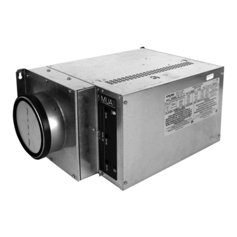
Stelpro MUA Series User manual

INSMUA0615
INSTALLATION GUIDE
MUA SERIES
MAKE UP AIR
REPLACEMENT COMPONENT LIST INCLUDED
For further information or to consult this guide online, please visit our website at www.stelpro.com
S
Y
S
T
È
M
E
Q
U
A
L
I
T
É
C
E
R
T
I
F
I
É
-
R
E
G
I
S
T
E
R
E
D
Q
U
A
L
I
T
Y
S
Y
S
T
E
M
This unit
complies with
the CSA and UL
standards

2INSMUA0615
LIST OF MODELS
Before installing and operating this product, the user and/or installer must read, understand and follow these instructions and keep them handy for future
reference. If these instructions are not followed, the warranty will be considered null and void and the manufacturer deems no further responsibility for this
product.
, according to the
effective in your region.
The following instructions must be adhered to in order to avoid personal injuries or property damages, serious injuries and potentially fatal electric shocks.
Make sure that all screws and electrical terminal connections are tightly secured before operating the unit in case they would have loosened during
transportation.
Protect the heating unit with the appropriate circuit breaker or fuse, in accordance with the nameplate.
Make sure the line voltage (volt) is consistent with that indicated on the unit’s nameplate.
This unit must be .
Switch off the power at the circuit breaker/fuse before installing, repairing and cleaning the unit.
Make sure the unit is appropriate for the intended use (if needed, refer to the product catalog or a representative).
indicated in the installation section.
void.
This unit must not come into contact with a water source and must be protected from splashes (e.g. a wet mop). Do not use it if any part has been immersed.
Moreover, do not turn it on or off when standing in water or if your hands are wet.
When cutting a piece of steel for the installation of the return duct, do not damage electrical wiring of the unit.
Because this unit is hot when in use, it may pose risks even in normal operation. Therefore, be and when using it. To avoid burns, do
not let bare skin touch hot surfaces. Let the unit cool down for a few minutes before handling it (it stays warm for some time after shut-down).
Some areas are dustier than others. Thus, it is the user’s responsibility to evaluate if the based on it. Accumulated dirt can lead
Thermal protection activation indicates that the unit has been subjected to abnormal operating conditions. If the thermal protection remains activated or
damaged. (Refer to the limited warranty).
Label all wires prior to disconnection when servicing controls. Wiring errors can cause improper and dangerous operation.
WARNING
instances, the instruction manual may not entirely match all the functions of the actual product. Therefore, the actual product and packaging, as well as the name
and illustration, may differ from the manual.
Model voltage aMperage flow
IN. KW AMPS DB
MUa06151 6 1.5 120 12.8 45 @ 90 48 @ 56
MUa0615 6 1.1/1.5 208/240 5.7/6.5 45 @ 90 48 @ 56
MUa0620 6 1.5/2.0 208/240 7.5/8.5 45 @ 90 48 @ 56
MUa0630 6 2.3/3.0 208/240 11.3/12.8 45 @ 90 48 @ 56
MUa0845 8 3.4/4.5 208/240 16.8/19.4 100 @ 200 48 @ 58
MUa0850 8 3.8/5.0 208/240 18.6/22.4 100 @ 200 48 @ 58
MUa0860 8 4.5/6.0 208/240 22.2/25.6 100 @ 200 48 @ 58
*
3INSMUA0615
MECHANICAL INSTALLATION
aBCd
IN. IN. MM IN. MM IN. MM IN. MM
612 305 21 7/8 556 17 3/8 441 8 5/8 219
814 1/2 368 29 737 24 3/8 620 12 3/8 314
INSTALLING THE DEVICE
Securely attach the device to a solid support. Devices with 8-in. collars
must be mounted from the ceiling using studs (not included).
TECHNICAL DRAWINGS
6'' COLLAR DIA. MODEL ONLY
FLOW
FLOW
FLOW
FLOW
1
4STUD
WASHER
HEXAGON NUT
A
DUCT
SIDE
TOP
FRONT
ISOMÉTRIC
D
B
C

4INSMUA0615
CHOOSE AN APPROPRIATE LOCATION TO INSTALL THE DEVICE:
door of the device).
INSTALLING THE DUCT SYSTEM
Keep the length of insulated ducts to a minimum to prevent choke and
improve ventilation.
ducts.
INSTALLING THE FRESH AIR INTAKE HOOD
ground.
-
meter outlet, dryer outlet, any other combustion source outlet.
-
ing to avoid turbulence, which could cause dust to enter the hood.
to the exterior hood (louver not included).
2 X MIN DIA. 2 X MIN DIA.
INSULATE THE INLET DUCT
FLOW
Tie wrap and
duct tape

5INSMUA0615
TYPICAL INSTALLATIONS:
It is strongly recommended to read the following instructions in order to correctly install the device according to the different installation
types. The two most frequently used installation methods are independent installation and installation connected to a forced air system.
This system functions independently and has its own ventilation duct sys-
-
or living room).
bathroom.
grill. This way, the cooler air will then cross the upper part of the room
and mix with room air before descending to occupant level.
than 300 ft./min., then the grill is too small. Replace it with a larger one.
FRESH AIR
MAXIMUM
Master bedroom 20 20
Bedroom 10 20
10 20
Living room 10 40
10 40
Dining room 10 25
4 2 1/4 or 3 1/4 X 10 40
5 2 1/4 or 3 1/4 X 10 65
6 4 1/4 or 4 X 10 110

6INSMUA0615
The second method consists of using the furnace distribution system to distribute fresh air. There are two methods of connecting the device to the
POWER CONNECTION
through it.
illustrated.
RETURN AIR SIDE CONNECTION
DISTRIBUTION AIR SIDE CONNECTION
RETURN
DISTRIBUTION
D + E = 2 FT MIN.
E
D
B
C
A
A+B+C= 10 FT MIN.
RETURN
DISTRIBUTION
CONNECTING THE LOW POWER CONTROL
main wall control. (6’’ model only).
one of the wall control according to the corre-
sponding terminals.
switch is used as an interlock between the unit and the exhaust fan by
passing one of the power leeds of the exhaust fan through the hole of
the current switch.
below.
unit. An auxiliary contact (external switch) can be connected to the
terminal block. This will allow unit to start the exhaust fan and function
simultaneously when required. Plug the exhaust fan switch in parallel
with the terminals as shown in the diagram.
L1
L2
N
EXHAUST FAN
WALL CONTROL
(6'' MODEL ONLY)
F
F
L1
N
EXTERNAL
SWITCH
EXHAUST FAN
30A MAX.

7INSMUA0615
ELECTRONIC CONTROL
OPERATION MODES
When the signal is lit, the unit will function in intermittent mode. Within the period of an hour, the unit operates and stops with the following
When the signal is lit, the fan runs at the speed at which the dimmer is set.
When the signal is lit, the fan runs at the maximum speed without passing through the dimmer.
The device is in stop mode when none of the signals are lit.
USER INTERFACE
PLENUM TEMPERATURE CONTROL POTENTIOMETER
The make up air is equipped with a plenum temperature sensor. You can select the plenum temperature set point with a potentiometer installed
1. 15/45 INTERMITTENT MODE
intermittent mode is selected.
2. 30/30 INTERMITTENT MODE
intermittent mode is selected.
3. 45/15 INTERMITTENT MODE
intermittent mode is selected.
4. HEATING
progress.
5. 15/45 INTERMITTENT MODE
15/45 intermittent mode.
6. 30/30 INTERMITTENT MODE
30/30 intermittent mode.
7. 45/15 INTERMITTENT MODE
45/15 intermittent mode.
LEGEND
1
6 75
23 4

8INSMUA0615
12345678910 11 12 13 14 15 16 17
A
B
C
D
E
F
G
H
I
J
K
12345678910 11 12 13 14 15 16 17
A
B
C
D
E
F
G
H
I
J
K
W1 W2
N
C-776
C-834
C-832
G R
HAR-123
HAR-094
C-771
GND
C-772
L1
dimmer
C-773
C-774 C-826
brown
black
terminal block
CL 2 40VA
24V
C-832
C-777 C-775
blue
HAR-096
auxiliary
contact
REL1.2
MAX: 25A-250V
REL1.1
1
2
1
2
M
RC
A
Contact
SSR
M
H1 H2
X1 X2
TRF-016
PROT2
SSR
CONT1
PROT1
SSR1
CONT1
REL2
REL2
Cap1
M1
E1
REL1
temperature sensor
4x C-757
C-781
C-781
HAR-028
+
C-825
WIRING DIAGRAM
1 2 3 4 56 7 8 9 10 11 12 13 14 15 16 17
A
B
C
D
E
F
G
H
I
J
K
1 2 3456 7 8 9 10 11 12 13 14 15 16 17
A
B
C
D
E
F
G
H
I
J
K
W1 W2
C-776
HAR-123
HAR-094
C-834
C-832
C-781
R
G
N
C-771
GND
C-772
L2
L1
dimmer
C-773
C-774 C-826
brown
black
CL 2 40VA
24V
C-832
C-777 C-775
blue
HAR-096
auxiliary
contact
REL1.2
MAX: 25A-250V
REL1.1
C-781
terminal block
4x C-757
1
2
3
a b
1
2
M
R C
A
Contact
SSR
M
TB2
PROT2
H1 H2
X1 X2
TRF200040D
SSR
CONT1
PROT1
SSR1
CONT1
REL2
REL2
Cap1
M1
REL1
E1
Temperature sensor

9INSMUA0615
FLOW CONTROL
PRELIMINARY STAGE
sq. ft 1 2-3 4-5 6-7 >7
<1500 30 45 60 75 90
1501 - 3000 45 60 75 90 105
3001 - 4500 60 75 90 105 120
4501 - 6000 75 90 105 120 135
6001 - 7500 90 105 120 135 150
>7500 105 120 135 150 165
ADJUSTING THE CONTROLS
-
1 2 3 4 56 7 8 9 10 11 12 13 14 15 16 17
A
B
C
D
E
F
G
H
I
J
K
1 2 3 4 56 7 8 9 10 11 12 13 14 15 16 17
A
B
C
D
E
F
G
H
I
J
K
24V
N
C-771
GND
HAR-123
C-772
C-776
L2
L1
C-828
CL 2 40VA
dimmer
C-829
C-775
C-773
C-774 C-826
REL1
C-779
4x C-757
HAR-094
C-779
C-834
C-832
brown
black
blue
HAR-096
C-827
G
W1 W2 R
terminal block
1
2
3
a b
M M
R C
A
Contact
SSR
M
PROT2
PROT3
H1 H2
X1 X2
TRF200040D
SSR
CONT1
PROT1
SSR1
CONT1
REL2
REL2
Cap1
M1
E2
REL1
E1
Temperature sensor

10 INSMUA0615
PERFORMANCE CURVE
0
0.1
0.2
0.3
0.4
0.5
0.6
0 50 100 150 200 250
Stac pressure (W.C)
Flow (CFM)
FAN PERFORMANCE CURVE
8'' model
6'' model
LOW
HIGH
FLOW
4. Turn on the device.
8. Re-verify the static pressure once the system has been balanced. Note that the static pressure may differ from the initial reading. Adjust the
1. Repeat steps 1 to 3 from the previous section.
2. Make sure that the device is working at the same time as the furnace fan.
3. It is not necessary to balance the air outlets, as they use the same distribution system as the furnace, and this step should have already been
done during the furnace installation.
5. Adjust the heating temperature.

11 INSMUA0615
ΔT (°F) 45 50 55 60 65 70 75 80 85 90 95 100
573 81 89 97 105 113 121 129 137 145 153 161
10 145 161 177 194 210 226 242 258 274 290 306 323
15 218 242 266 290 315 339 363 387 411 435 460 484
20 290 323 355 387 419 452 484 516 548 581 613 645
25 363 403 444 484 524 565 605 645 685 726 766 806
30 435 484 532 581 629 677 726 774 823 871 919 968
35 508 565 621 677 734 790 847 903 960 1016 1073 1129
40 581 645 710 774 839 903 968 1032 1097 1161 1226 1290
45 653 726 798 871 944 1016 1089 1161 1234 1306 1379 1452
50 726 806 887 968 1048 1129 1210 1290 1371 1452 1532 1613
55 798 887 976 1065 1153 1242 1331 1419 1508 1597 1685 1774
60 871 968 1065 1161 1258 1355 1452 1548 1645 1742 1839 1935
65 944 1048 1153 1258 1363 1468 1573 1677 1782 1887 1992 2097
70 1016 1129 1242 1355 1468 1581 1694 1806 1919 2032 2145 2258
75 1089 1210 1331 1452 1573 1694 1815 1935 2056 2177 2298 2419
80 1161 1290 1419 1548 1677 1806 1935 2065 2194 2323 2452 2581
85 1234 1371 1508 1645 1782 1919 2056 2194 2331 2468 2605 2742
90 1306 1452 1597 1742 1887 2032 2177 2323 2468 2613 2758 2903
95 1379 1532 1685 1839 1992 2145 2298 2452 2605 2758 2911 3065
100 1452 1613 1774 1935 2097 2258 2419 2581 2742 2903 3065
105 1524 1694 1863 2032 2202 2371 2540 2710 2879 3048
ΔT (°F) 105 110 115 120 125 130 135 140 145 150
5169 177 185 194 202 210 218 226 234 242
10 339 355 371 387 403 419 435 452 468 484
15 508 532 556 581 605 629 653 677 702 726
20 677 710 742 774 806 839 871 903 935 968
25 847 887 927 968 1008 1048 1089 1129 1169 1210
30 1016 1065 1113 1161 1210 1258 1306 1355 1403 1452
35 1185 1242 1298 1355 1411 1468 1524 1581 1637 1694
40 1355 1419 1484 1548 1613 1677 1742 1806 1871 1935
45 1524 1597 1669 1742 1815 1887 1960 2032 2105 2177
50 1694 1774 1855 1935 2016 2097 2177 2258 2339 2419
55 1863 1952 2040 2129 2218 2306 2395 2484 2573 2661
60 2032 2129 2226 2323 2419 2516 2613 2710 2806 2903
65 2202 2306 2411 2516 2621 2726 2831 2935 3040 3145
70 2371 2484 2597 2710 2823 2935 3048 3161 3274 3387
75 2540 2661 2782 2903 3024 3145 3266 3387 3508 3629
80 2710 2839 2968 3097 3226 3355 3484 3613 3742 3871
85 2879 3016 3153 3290 3427 3565 3702 3839 3976 4113
90 3048 3194 3339 3484 3629 3774 3919 4065 4210 4355
95 3218 3371 3524 3677 3831 3984 4137 4290 4444 4597
100 3387 3548 3710 3871 4032 4194 4355 4516 4677 4839
105 3556 3726 3895 4065 4234 4403 4573 4742 4911 5081
ΔT (°F) 155 160 165 170 175 180 185 190 195 200
5250 258 266 274 282 290 298 306 315 323
10 500 516 532 548 565 581 597 613 629 645
15 750 774 798 823 847 871 895 919 944 968
20 1000 1032 1065 1097 1129 1161 1194 1226 1258 1290
25 1250 1290 1331 1371 1411 1452 1492 1532 1573 1613
30 1500 1548 1597 1645 1694 1742 1790 1839 1887 1935
35 1750 1806 1863 1919 1976 2032 2089 2145 2202 2258
40 2000 2065 2129 2194 2258 2323 2387 2452 2516 2581
45 2250 2323 2395 2468 2540 2613 2685 2758 2831 2903
50 2500 2581 2661 2742 2823 2903 2984 3065 3145 3226
55 2750 2839 2927 3016 3105 3194 3282 3371 3460 3548
60 3000 3097 3194 3290 3387 3484 3581 3677 3774 3871
65 3250 3355 3460 3565 3669 3774 3879 3984 4089 4194
70 3500 3613 3726 3839 3952 4065 4177 4290 4403 4516
75 3750 3871 3992 4113 4234 4355 4476 4597 4718 4839
80 4000 4129 4258 4387 4516 4645 4774 4903 5032 5161
85 4250 4387 4524 4661 4798 4935 5073 5210 5347 5484
90 4500 4645 4790 4935 5081 5226 5371 5516 5661 5806
95 4750 4903 5056 5210 5363 5516 5669 5823 5976
100 5000 5161 5323 5484 5645 5806 5968
105 5250 5419 5589 5758 5927 6097
NOTE : FOR ALL VALUES NOT SHOWN ON THIS CHART, YOU CAN USE THIS FOLLOWING FORMULA:
WATTS = (air flow CFM) X (delta TEMP. deg. F) / 3,1
AIR FLOW (CFM) - MUA08
AIR FLOW (CFM) - MUA06
AIR FLOW (CFM) - MUA08
REQUIRED POWER (WATTS) BASED ON AIR FLOW AND TEMPERATURE RISE

12 INSMUA0615
proBleM
The device does not work Make sure the device is connected
Run the device in high-speed until the condensation evaporates
The air flowing from the distribution grills is too cold.
Run the device in low-speed or intermittent mode
The device suddenly stops working Reset the manual protection located on the heating element plates
If the problem persists, call the technical support service
The device overheats and/or the elements cycle.
Increase the minimum speed of the fan
If the problem persists, call the technical support service
TROUBLESHOOTING
Minimal maintenance of the device is required for it to function optimally throughout the year. It is
recommended to clean the exterior hood of the fresh air intake once per year.
Disconnect the power supply to the circuit breaker/fuse before cleaning the device. Dust the device
regularly to prevent dust from accumulating, which could cause the device to overheat. If the device
is located in a very dusty area, use a vacuum cleaner with a dust brush attachment to clean the
device.
MAINTENANCE

13 INSMUA0615
REPLACEMENT COMPONENT LIST
1
2
3
4
5
6
7
8
9
10
11
12
12
12
12
13
14
15
16
17
60TX15
18
19
20 KIT-MUA-SWI
21 TB-004
22 TB-006-3
23 TB-007-2
22 18
16
15
10 8
914
7
11
23
6
12
21
6
1
3
6'' COLLAR DIA. MODEL
11
922
12
17
7
16
13
8
1021
5
6
23
8'' COLLAR DIA. MODEL

14 INSMUA0615
STELPRO DESIGN INC. | Saint-Bruno-de-Montarville | Québec | J3V 6L7STELPRO DESIGN INC. | Saint-Bruno-de-Montarville | Québec | J3V 6L7
. Subject to the terms of this warranty, Stelpro warrants its products and their components against defects in
. This warranty applies only
to the original purchaser; it is non-transferable and cannot be extended.
If at any time during the warranty period the unit becomes defective, you must cut off the power supply at the main electrical panel and contact 1) your
installer or distributor, 2) your service center or 3) Stelpro’s customer service department. In all cases, you must have a and
provide the. Stelpro reserves the right to examine or to ask one of its representatives to examine
the product itself or any part of it before honoring the warranty. Stelpro reserves the right to replace the entire unit, refund its purchase price or repair a
1-800-363-34141-800-343-1022(consumers).
This warranty is exclusive and in lieu of all other representations and warranties (except of title), expressed or implied, and Stelpro expressly disclaims
Stelpro’s liability with respect to products is limited as provided above. Stelpro shall not be subject to any other obligations or liabilities whatsoever,
whether based on contract, tort or other theories of law, with respect to goods or services furnished by it, or any undertakings, acts or omissions relating
thereto. Without limiting the generality of the foregoing, Stelpro expressly disclaims any liability for property or personal injury damages, penalties,
disclaims all consequential, incidental and contingent damages whatsoever.
maintenance, improper maintenance (other than that prescribed by Stelpro) or a use other than that for which the unit was designed; 3) a natural disaster
damages, etc. This warranty does not cover any accidental or intentional losses or damages, nor does it cover damages caused by negligence of the
user or owner of the product. Moreover, it does not cover the cost of disconnection, transport, and installation.
The warranty is limited to the repair or the replacement of the unit or the refund of its purchase price, . Any parts
period. This warranty will be considered null and void and Stelpro will have the right to refuse any claims if without the
or discoloration caused by excessive heat, chemical cleaning products and abrasive agents. It does not cover any damage that occurred during the
shipping.
Some states and provinces do not allow the exclusion or limitation of incidental or consequential damages and some of them do not allow limitations on
have other rights which vary from state to state or from province to province.
LIMITED WARRANTY LIMITED WARRANTY LIMITED WARRANTY LIMITED WARRANTY LIMITED WARRANTY
LIMITED WARRANTY LIMITED WARRANTY LIMITED WARRANTY LIMITED WARRANTY
LIMITED WARRANTY
This manual suits for next models
7
Table of contents
Other Stelpro Fan manuals

Stelpro
Stelpro ULTRA SILENCIEUX Series User manual

Stelpro
Stelpro SBFHL070 User manual

Stelpro
Stelpro BF SERIES User manual

Stelpro
Stelpro BFQ Series User guide

Stelpro
Stelpro ULTRA QUIET Series User manual

Stelpro
Stelpro SQBF070 User manual

Stelpro
Stelpro SBF050 User manual

Stelpro
Stelpro BFNHL User manual

Stelpro
Stelpro MAKE UP AIR MUAA Series User manual
Popular Fan manuals by other brands

Aerofanture
Aerofanture SWITCH AT52-01-01B installation manual

SODECA
SODECA WALL/DUCT user manual

S&P
S&P RED Installation, operation and maintenance manual

Harbor Breeze
Harbor Breeze 41161 manual

Home Decorators Collection
Home Decorators Collection TAGER N383C-MBK Use and care guide

Bestron
Bestron DCF52LSR instruction manual