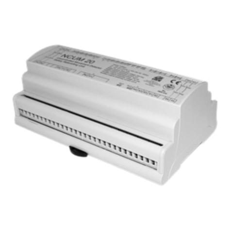
Stem NCBM 01 User manual

MANUAL NCBM 01 Revision 14 11/06/2021
STEM S.r.l. via della Meccanica, 2 I-27010 Cura Carpignano- Pavia Italia Tel. +39 0382 583011 Fax +39 0382 583058 www.stemsrl.it stem@stemsrl.it
Subject to change without notice, no responsibility will be taken for every detail. © STEM S.r.l.
NCBM 01
1 Introduction
The control unit NCBM 01 can be used to realize the automatic monitoring
systems of a built in redundancy devices , as requested by EN81-20 against
uncontrolled movement.
For the hydraulic elevators:
NCBM01 allows to periodically monitor the functioning of the two down
direction valves, connected in series and controlled in sync.
It also permits the control the activation ad deactivation phase of the single
additional valves.
For traction lift with brakes:
NCBM01 allows to monitor the brakes of gearless/geared machine controlling at
each lift travel the safety micro switches mounted on the brake.
For traction lifts with uncontrolled movement device on the OSG(over speed
governor):
NCBM01 allows to monitor the proper functioning of the blocking element
(electromagnet) installed on the OSG
All the stopping element : down direction valves, electrical brakes and the OSG
must be certified.
Main features:
•activation of an output relay, in case of failure of the test.
•Reset button to manually restore the normal operation of the device
after alarm activation
•HW redundant circuitry of the micro-controller section that will activate the alarm relay in the case
where the test has not been performed within 38 hours.
•internal clock to the time configuration of the test (e.g. during the night).
•Hour configuration using a button
•6 LEDs to signalize alarms and operating status
•USB port and software application for configuring the unit allowing maximum flexibility to insert test
and operational parameters.
During electrical cabinet assembly a fast parameter download is possible selecting the appropriate file

MANUAL NCBM 01 Revision 14 11/06/2021
STEM S.r.l. via della Meccanica, 2 I-27010 Cura Carpignano- Pavia Italia Tel. +39 0382 583011 Fax +39 0382 583058 www.stemsrl.it stem@stemsrl.it
Subject to change without notice, no responsibility will be taken for every detail. © STEM S.r.l.
2 Operation for hydraulic lift
The hydraulic lift can use 3 different uncontrolled movement systems:
•With Single blocking additional valve
•With double valves monitored.
•Bucher I-VALVE signal control
2.1 Electrical connection scheme for hydraulic lift
BTAMP 12V
D2
A4
A3
D1
NCBM 01
Voltage reference / N (AC)
+24VDC / L1(AC)
Car Door
VARISTOR
V2
PO1
PO2
V1
Speed
VARISTOR
JP3
Voltage reference
N (AC)
DOWN
+24VDC / L1(AC)
TEST
JP2
A2
T2
T1
A1
JP1
VARISTOR
FNO
Voltage reference / N (AC)
VARISTOR
VARISTOR
J3
PT1
PT2
S2
S1
Floor
+24VDC / L1(AC)
Up
End of the
safety chain
Solenoid valve V1
Solenoid valve V2
J2
FNC
CF
J1
K1
K2
Fault Relay
Door contact
Door Bypass
CO
TW
O1
O2
Test warning
FIG. 1 Electrical scheme connection for hydraulic lift
2.2 System with single additional valve
Some manufacturers of valves, provide the possibility of using an additional valve block which must be opened first
and closed after the main valve of descent. In this case, the valve does not work under pressure and not being
considered in parallel to the main valve of descent does not require monitoring.
The NCBM01 allows to select the activation sequence valve by setting the parameter "valve sequence" in the
configuration window. Using the parameter "down valve opening delay" the advance opening time of the additional
valve is configured, while the parameter "down valve closing delay" determines the delayed additional valve closing
time.
The periodic test, in this configuration, is disabled. To activate the valves the doors have to be closed (presence of
voltage on P01,P02, LED4 off). Needed connections: down, up, speed, power supply, outputs (CO1, O1,O2)
2.3 System with double valves monitored
In the case of double valve system monitored and controlled in parallel, the manufacturers prescribe the obligation to
perform a test for periodic monitoring through the concept of "built in redundancy" introduced by the regulations EN81-
20
In this case, the device NCBM01 performs test at the hour set in the parameter "test time" written during the
configuration of the device. The test is repeated daily or hourly according to the parameter "test frequency" set
The conditions that must occur to begin the test are:
• Scheduled time
• Contactors up, down, speed must be turned off, doors closed (voltage between P01-P02, LED4 off) for at
least 30 seconds and lowest floor signal present (voltage present between PT1,PT2 LED 5 ON).

MANUAL NCBM 01 Revision 14 11/06/2021
STEM S.r.l. via della Meccanica, 2 I-27010 Cura Carpignano- Pavia Italia Tel. +39 0382 583011 Fax +39 0382 583058 www.stemsrl.it stem@stemsrl.it
Subject to change without notice, no responsibility will be taken for every detail. © STEM S.r.l.
If the above conditions are met the test will start by opening the output O1 (valve V1 closed in testing) and maintaining
the output O2 closed so that the valve V2 will remain open. The duration of the test valve is set via the parameter “test
duration” in the configuration user interface, after the test of the first valve, after 5 seconds it will proceed to the tests
of the second valve in a similar manner (activate O1, O2 deactivated). In case a leveling command is activated (up
command active without speed signal within 5 second), the test is repeated. If during the second attempt a leveling
command is activated again the test failed. The alarm is signaled by the fault relay and the lighting of the LED
indicators. After a switch on/off of the NCBM01 the alarm remain activated until the reset button is pusher for at least
5 seconds. If, during the test one of the following commands: door open or down or up followed by the speed within
5s, the test is suspended.
If a frequency daily tests is set, the device has a time-out for the execution of the test of one hour. If the test is not
performed within 1 hour an alarm is generated. If it is set the tests frequency of one hour, there is no time-out
The parameters for the handling of activation delay of the valves, during normal elevator operation, are configured
using the masks "Valve sequence", "down valve closing delay", "down valve opening delay", as described in the
previous paragraph.
Thirty seconds before the execution of the test and for the whole duration of the same, the output TW (test warning)
will remain active to signal the imminent execution of the test. This function is useful to signal to the control cabinet the
test coming and to perform the commands necessary for the preparation of the test : door closing, lowest floor...
2.4 Bucher I-VALVE signal control
FIG. 2 Electrical scheme connection for hydraulic lift
The configuration Bucher I-VALVE allows to control the timing of the SMA signal when the travel signal is changing
the state. As indicated in the valve manual, the system detects the error1 and error2:
Error 1 : when travel command goes from high level to low level, the SMA signal should change the state from 0.1s to
1s after the travel signal change, if the timing is not respected error1 has to be detected
Error 2 : when travel command goes from low to high level, the SMA signal should change the state within 0.1s after
the travel signal change, if the timing is not respected error2 has to be detected
If the error is detected the Fault relay will change state according to the relay polarity selected in the SW configuration
•FNO, in case of alarm FNO, CF is closed
•FNC, in case of alarm FNC,CF is closed
Led 3, Led4 and led5 continues to signal the state of the SMA and TRAVEL commands even if NCBM is in alarm
The alarm will be maintained until a manual reset will be performed.
JP1
T2
D2
D1
JP3
V1
PO2
JP2
T1
A2
A1
PO1
V2
J1
FNC
J2
CF
S1
S2
J3
FNO
K2
Fault Relay
K1
PT2
PT1
A3
A4
NCBM 01
+24VDC / L1(AC)
TRAVEL
COMAND
SMA
SIGNAL
CO
TW
O1
O2

MANUAL NCBM 01 Revision 14 11/06/2021
STEM S.r.l. via della Meccanica, 2 I-27010 Cura Carpignano- Pavia Italia Tel. +39 0382 583011 Fax +39 0382 583058 www.stemsrl.it stem@stemsrl.it
Subject to change without notice, no responsibility will be taken for every detail. © STEM S.r.l.
FIG. 3 Bucher I-valve signals
2.5 Signalling Hydraulic mode
Using the function LED functionality of the user interface SW is possible select the led options.
NORMAL FUNCTIONALITY HYDRO
MONITOR / NOMONITOR
BUCHER I-VALVE
LED
(OPZ1)
(OPZ2)
LED1(GREEN)
Up(On/Off)
Valve V1
OFF
LED2 (GREEN)
Down (On/Off)
Valve V2
OFF
LED3 ((GREEN)
High speed (On/Off)
POWER OK
Blink if travel low / On if travel high
LED4 (GREEN)
Doors (On/Off)
Doors (On/Off)
SMA signal, on if high
LED5 (GREEN)
Lower floor (On/Off)
Lower floor (On/Off)
Time verification pending, On until SMA signal change
the state
ALL (RED)
Alarm (Off)
Alarm (Off)
Alarm (Off)
TAB. 1 Led Meaning in normal functionality monitor / nomonitor / I-Valve configuration
TEST PENDING
TEST IN PROGRESS
LED
(OPZ1)
(OPZ2)
(OPZ1)
(OPZ2)
LED1
(Green)
Up (On/Off)
Valve V1 (O1 out
On/Off)
Off
Valve V1 (O1 out On/Off)
LED2
(Green)
Down (On/Off)
Valve V2(O2 out
On/Off)
Off
Valve V2(O2 out On/Off)
LED3
(Green)
Test pending (Led blink)
Test pending (Led
blink)
Test pending (Led blink)
Test pending (Led blink)
LED4
(Green)
Doors (On= open
Off=closed)
Doors (On= open
Off=closed)
Doors (On= open
Off=closed)
Doors (On= open
Off=closed)
LED5
(Green)
Lower floor (On=at floor
/Off =not at floor)
Lower floor (On=at
floor /Off =not at
floor)
Test in progress (led blink)
Test in progress (led blink)
ALL (Red)
Alarm (Off)
Alarm (Off)
Alarm(Off)
Alarm (Off)
TAB. 2 Led Meaning during test monitoring pending or in execution

MANUAL NCBM 01 Revision 14 11/06/2021
STEM S.r.l. via della Meccanica, 2 I-27010 Cura Carpignano- Pavia Italia Tel. +39 0382 583011 Fax +39 0382 583058 www.stemsrl.it stem@stemsrl.it
Subject to change without notice, no responsibility will be taken for every detail. © STEM S.r.l.
ALARM
Severity
Restore
LED1
LED2
LED3
LED4
LED5
ALL
Relay
fault
Monitoring fault valve1
Unit
blocked
RESET
Button
ON
OFF
OFF
OFF
OFF
ON
ON
Monitoring fault valve12
Unit
blocked
RESET
Button
OFF
ON
OFF
OFF
OFF
ON
ON
Time out test, test not done in
time
Unit
blocked
RESET
Button
ON
ON
OFF
OFF
OFF
ON
ON
Bucker-Ivalve (error 1)
Unit
blocked
RESET
Button
ON
OFF
Blink/ON
x
x
ON
ON
Bucker-Ivalve (error 2)
Unit
blocked
RESET
Button
OFF
ON
Blink/ON
x
x
ON
ON
TAB. 3 Led Meaning in case of alarm
2.6 Activation of the valves during an upward travel (monitor / no monitor config.)
Using the configuration window "Opening Up Valve Timing", you can configure the opening of a single or both valves
during upward elevator travel. The maximum opening time is configurable to 4s.
Checking the box "always on", you can configure the continuous opening of the valves during an upward travel. If in
the configuration menu the box V1,V2 and “always on” are selected together, the opening and closing of the valves are
handled according to the parameter set in the menus “Valve sequence”, “down Opening Valve Delay” e “Down
Closing Valve Delay”.
3 Working principle for traction lift
In the case of traction lift, as elements to stop the elevator car can be used the electrical machine brake or the safety
gear driven by the speed limiter by means of a coil.
3.1 Electrical connection scheme for traction lift
FIG. 4 Scheme for electrical lift
BRAKE
VARISTOR
D1
D2
A4
A3
NCBM 01
MICROSWITCH 1
MICROSWITCH 2 PO2
V1
JP3
V2
PO1
+24VDC / L1(AC) A1
JP1
A2
T2
JP2
T1
Fault Relay
J3
S2
S1
PT1
FNO
CF
PT2
+24VDC / L1(AC)
MICROSWITCH 3
MICROSWITCH 4
J1
K1
J2
FNC
K2 O2
O1
TW
CO

MANUAL NCBM 01 Revision 14 11/06/2021
STEM S.r.l. via della Meccanica, 2 I-27010 Cura Carpignano- Pavia Italia Tel. +39 0382 583011 Fax +39 0382 583058 www.stemsrl.it stem@stemsrl.it
Subject to change without notice, no responsibility will be taken for every detail. © STEM S.r.l.
3.2 Operation as a monitoring system for electric brakes
If the elevator is equipped with electric certified brakes, it’s possible monitoring them checking the safety microswitch
on the brakes at each change of state (open / close). The NCBM controls at each lift travel the status of the microswitch
and if an anomaly is detected triggers the alarm resettable via the manual button.
it s possible to monitor 2,3 or 4 safety switches, the configuration is selectable using the user interface SW.
The device receives the brake command and after a configurable time (default 5 seconds) checks the status of the
microswitch. If the status is not correct the fault signal will be generated and the LED will indicate the possible fault on
the brake.
The microswitch can be:
•Normally closed (NC) check the opening of the contact when the brake is activated (coil not energized).
•Normally open (NO) check the opening of the contact when the brake is activated (coil not energized).
In this configuration (electric lift) it’s possible to select the polarity of the fault output using configuration SW trough
the parameter “fault relay polarity”:
•FNO, in case of alarm FNO, CF is closed
•FNC, in case of alarm FNC,CF is closed
3.3 Signalling traction lift
LED
Brakes deactivated
No Alarm
Brakes activated
Brakes deactivated
with alarm
Brakes activated with
alarm
LED1(GREEN)
OFF (Contact1)
OFF (Contact 1)
ON if contact 1 faulty
ON if contact 1 faulty
LED2 (GREEN)
OFF (Contact 2)
OFF (Contact 2)
ON if contact 2 faulty
ON if contact 2 faulty
LED3 (GREEN)
ON (POWER OK)
ON blink (brake
activated)
ON blink (brake
activated)
ON blink (brake
activated)
LED4 (GREEN)
OFF (Contact 3)
OFF (Contact 3)
ON if contact 3 faulty
ON if contact 3 faulty
LED5 (GREEN)
OFF (Contact 4)
OFF (Contact 4)
ON if contact 4 faulty
ON if contact 4 faulty
ALL (RED)
Alarm (Off)
Alarm (Off)
ON
ON
Unit blocked, relay fault ON, restore using the reset
button
TAB. 4 Signaling for traction lift
4 Monitoring system for OSG blocking coils
4.1 Working principle as OSG monitoring
Where it is used the certified speed limiter as an element able to activate the overspeed governor in the event of
uncontrolled movement, it involves the use of an electromagnet which pushes a pivot to lock the wheel of the
mechanical limiter.
The OSG is equipped with a sensor (usually mechanical microswitch or inductive) that allows to detect the position of
the locking pivot activated by the electromagnet coil. This contact can be monitored by NCBM01.
Currently, there are two types of certified overspeed governor:
1. With coil released and activated and each arrival / departure from the floor
2. With coil always activated and released only in the event of uncontrolled movement
The type 1) can be monitored as an electric brake so please refer to section 3.1
The type 2) is described below.

MANUAL NCBM 01 Revision 14 11/06/2021
STEM S.r.l. via della Meccanica, 2 I-27010 Cura Carpignano- Pavia Italia Tel. +39 0382 583011 Fax +39 0382 583058 www.stemsrl.it stem@stemsrl.it
Subject to change without notice, no responsibility will be taken for every detail. © STEM S.r.l.
4.2 Wiring diagrams for overspeed governors
FIG. 5 Connections scheme for monitoring OSG type1
FIG. 6 Connections scheme for monitoring OSG type2
VARISTOR
Electromagnet
driver
D1
A3
D2
A4
BTAMP 12V
JP3
JP1
JP2
+24V
Electromagnet
OSG
Microswitch
TEST
A1
A2
T1
_
V1
T2
PO1
V2
PO2
J1
K1
Fault Relay
NCBM 01
K2
-
J3
FNO
S2
CF
J2
FNC
PT1
PT2
S1
CO
TW
O1
O2
VARISTOR
Down
BTAMP 12V
D1
D2
A4
A3
+24VDC / L1(AC)
TEST
Voltage reference / N (AC)
VARISTOR PO2
V2
PO1
V1
R=1Kohm
not needed with
NCUM Module JP3
Voltage reference
N (AC)
+24VDC / L1(AC)
T2
JP2
A2
T1
A1
JP1
Fault Relay
K2
K1
NCBM 01
J2
J1
FNC
FNO
PT2
PT1
S1
S2
J3
CF
+24VDC / L1(AC)
Floor
VARISTOR
Voltage reference / N (AC)
Test is coming
Control panel
A3 Safety
circuit
OSG
Microswitch
ELETTROMAGNET
Voltage reference / N (AC)
CO
TW
O1
O2
Test warning

MANUAL NCBM 01 Revision 14 11/06/2021
STEM S.r.l. via della Meccanica, 2 I-27010 Cura Carpignano- Pavia Italia Tel. +39 0382 583011 Fax +39 0382 583058 www.stemsrl.it stem@stemsrl.it
Subject to change without notice, no responsibility will be taken for every detail. © STEM S.r.l.
4.3 Working principle in case of OSG actuated only in the event of uncontrolled
movement
The NCBM01 unit allows to configure, using the SW interface, the time at which you want to run the test and its
frequency (eg once a day). If the following conditions are true:
•elevator stopped for at least 30s
•elevator to the lowest floor
•closed doors
•test time
•Led configuration to start the test: LED2,5 on, LED3 flashing
one of the following tests will start
Test option1:
1. the power supply contact of the electromagnet (O1) will be open
2. In a maximum time of 3 seconds the NCBM checks the microswitch status installed on the OSG (NC closed
when OSG free to move, LED2 off)
3. if the contact remain closed the alarms will be activated.
4. If there were no alarms, the electromagnet is power supplied again (LED2 ON)
5. The contact will close again, if it remains open the alarm will be activated.
Test option2 (to be used for example in conjunction with the product Stem NCUMxx):
1. A test impulse of 300ms is sent on the O1 output
2. After a set time (default 3s) the status of the microswitch installed on the OSG is checked (NC closed
when OSG free to move, LED2 OFF then ON)
3. If the test fails, the alarms will be activated
In both cases the signaling outputs activated are:
• TW (test warning), thirty seconds before the execution of the test and for the duration of the whole test, to signal
to the control cabinet the test coming and to perform the commands necessary for the preparation of the test : door
closing, lowest floor, stop of the elevator
• O2 about 10 seconds before the test is performed, to signal the imminent execution of the test to the control
panel. This information is useful to prevent a up/down command given at the same time of the O1opening, that
may cause the operation of the safety gear.
During the waiting phase of the test (30s), the commands UP, down, door opening and lowest floor if activated will
delay the test execution.
4.4 Signaling
LED
Normal working
Test pending
Alarme activated
LED1(Green)
UP/down (On if active)
UP/down (On if active)
On
LED2
(Green)
OSG contact (On if closed)
OSG contact (On if closed)
On
LED3
(Green)
ON
Test pending (blink.)
Off
LED4
(Green)
Doors (On if open/Off
closed)
Doors (On if open/Off
closed)
Off
LED5
(Green)
Lowest floor (On at floor)
Lowest floor (On at floor)
Off
ALL (RED)
Alarm (Off)
Alarm (Off)
Alarm (On)
Unit blocked, relay fault ON, restore using the reset
button
TAB. 5 Signaling for OSG application

MANUAL NCBM 01 Revision 14 11/06/2021
STEM S.r.l. via della Meccanica, 2 I-27010 Cura Carpignano- Pavia Italia Tel. +39 0382 583011 Fax +39 0382 583058 www.stemsrl.it stem@stemsrl.it
Subject to change without notice, no responsibility will be taken for every detail. © STEM S.r.l.
5 Generic alarm valid for all configurations
ALARM
Severity
Restore
LED1
LED2
LED3
LED4
LED5
ALL
Relay fault
Battery
No Block
Automatic
OFF
OFF
OFF
OFF
ON
ON
OFF
RTCC Alarme
No Block
Automatic
OFF
OFF
ON
OFF
OFF
ON
OFF
Alarme memory write
No Block
Automatic
OFF
OFF
OFF
ON
OFF
ON
OFF
Allrm time out HW
Block
RESET Button
OFF
OFF
ON
OFF
OFF
ON
ON
TAB. 6 Generic alarm valid for all configurations
6 HW redundancy circuitry
The NCBM is equipped with a redundancy HW circuit that in case the test is not performed within a 38-hour generates
an alarm. The reset is possible only by pressing the reset button.
Each time the monitoring test is performed, the internal counter is reset by the change of status of the outputs O1-O2
and subsequent activation of the V1-V2 (to be connected in any application hydraulic, electrical and OSG)
7 Internal clock management
The device has an internal clock that thanks to the battery, continues to operate even in the absence of main power
supply. Clock adjustment can be accomplished using the SW interface or by using the buttons on the NCBM unit.
Pressing the TIME button for 5 seconds, the current time is displayed by blinks of the led3: every flash corresponds to
one hour.
Pressing the time and reset button for about 3 seconds allows to enter in configuration mode: the LED1 will light and
every time you press the button “time” you will add 1 hour (example: if I need to set the 10 o clock, we must press
“TIME”10 times ). LED4 will flash each time you press the button.
8 Battery and operation in case of power failure
In case of power failure the NCBM01 keeps in operation only internal clock. After the return of the supply voltage, the
control unit restores its normal operation within 1 minute.
The customer can select to use external 12V battery connected to the inputs A3-A4 or to use an internal battery inserted
on the front side. The internal battery should be type CR2032 220mAh the “+” polarity toward the upper part of the
device (tampo-print side). To avoid unexpected behavior when replacing the battery, it is suggested to insert it when the
control unit is on. The battery is used only to keep the clock updated, in case of traction lift configuration or hydraulic
without monitor it can be not used
9 START UP AND E PERIODIC INSPECTION
9.1 HYDRAULIC LIFT WITH MONITORING
1. Set through the user interface SW related parameters
2. Do some test runs up and down checking through the LEDs 1 to Led5 (Option 1 and Option 2) that the
received signals from the system are correct and the LED FAULT is not activated.
3. Simulate the operation of re-leveling and checks by means of the LEDs1 to Led5 (Option 1 and Option 2) that
the received signals from the system are correct and the LED FAULT is not activated.
4. PERIODIC TEST SIMULATION SUCCESSFULLY PERFORMED: With the system stopped at the
bottom floor and with closed doors, turn on the test input (T1 to GND, T2 to 24VAC/DC) by means of an
external pushbuttons. The test monitoring will start opening one valve at a time. If the LED fault remain off,
the test is considered passed
5. PERIODIC TEST SIMULATION WITH NEGATIVE RESULT AT VALVE V1:With the system
stopped at the bottom floor and with closed doors, turn on the test input (T1 to GND, T2 to 24VAC/DC) by
means of an external pushbuttons. During the valve V1 test (V2 open) simulate a re-leveling, once the car
position is OK wait for the restart of the test (Led3/led5 flashing) and simulate again a re-leveling. The test is
considered passed if the control unit will activate the alarm LED and the fault relay will change state.

MANUAL NCBM 01 Revision 14 11/06/2021
STEM S.r.l. via della Meccanica, 2 I-27010 Cura Carpignano- Pavia Italia Tel. +39 0382 583011 Fax +39 0382 583058 www.stemsrl.it stem@stemsrl.it
Subject to change without notice, no responsibility will be taken for every detail. © STEM S.r.l.
6. PERIODIC TEST SIMULATION WITH NEGATIVE RESULT AT THE POWER ON:
after the alarm generated at the step 5) remove and reconnect the power supply make sure that the alarm
remains active, then press the reset button for approximately 5 seconds to reset the faulty condition.
7. PERIODIC TEST SIMULATION WITH NEGATIVE RESULT AT VALVE V2:with the system
stopped at the bottom floor and with closed doors, turn on the test input (T1 to GND, T2 to 24VAC/DC) by
means of an external pushbuttons. During the valve V2 test (V1 open) simulate a re-leveling. Once the car
position is OK, wait for the restart of the test (Led3/led5 flashing) and simulate again a re-leveling. The test is
considered passed if the control unit will activate the alarm LED and the fault relay will change state.
8. Do again the point 6
9. Checks the time and eventually set it to the correct value.
9.2 HYDRAULIC LIFT WITH BUCHER I-VALVE
1. Set through the user interface SW related parameters
2. Do some test runs up and down checking through the LEDs that received signals from the system are correct
and the LED ALL and the relay FAULT are not activated.
3. I-VALVE ERROR 1 DETECTED: disconnect the SMA signal, travel command high (run elevator) than
travel command low (stop the elevator), checks activation of the relay alarm and the correct led status
4. I-VALVE ERROR 2 DETECTED: connect the P01 to 24V, travel command high (run elevator), checks
activation of the relay alarm and the correct led status
9.3 TRACTION LIFT USING BRAKES
1. Set through the user interface SW related parameters
2. Do some test runs up and down checking through the LEDs 1 to Led5 (Option 1 and Option 2) that the
received signals from the system are correct and the LED FAULT is not activated.
3. TEST SIMULATION WITH NEGATIVE RESULT: simulate a non opening and a non-closing of the
microswitch per each of them which is used.
4. TEST SIMULATION WITH NEGATIVE RESULT AT THE POWER ON:
after the alarm generated at the step 3) switch on and off the power supply make sure that the alarm remains
active, then press the reset button for approximately 5 seconds to reset the faulty condition.
5. Checks the time and eventually set it to the correct value.
9.4 TRACTION LIFT USING OSG
1. Set through the user interface SW related parameters
2. Do some test runs up and down checking through the LEDs 1 to Led5 (Option 1 and Option 2) that the
received signals from the system are correct and the LED FAULT is not activated.
Type 1 OSG with electromagnet released each time the elevator stops at floor:
Perform the test 8.2 from points 3 to 5
Type 2 OSG with electromagnet released only in case of undeteced movement
Option 1:
1. TEST SIMULATION SUCCESSFULLY PERFORMED: With the system stopped at the bottom
floor and with closed doors, turn on the test input (T1 to GND, T2 to 24VAC/DC) by means of an
external pushbuttons. After the pending time (30s), the test sequence will start, with the opening and
subsequent closing output O1 in series with the electromagnet. If there is proper switching sequence
on the OSG contact: opens when O1 opens, closes when O1 closes, the test ends successfully
2. TEST SIMULATION WITH NEGATIVE RESULT (contact failure to open):
a. Jumper output O1 so that the electromagnet remains always powered
b. With the system stopped at the bottom floor and with closed doors, turn on the test input (T1
to GND, T2 to 24VAC/DC) by means of an external pushbuttons. After the pending time
(30s), the test sequence will start opening the output O1, but the microswitch will not change
state because the electromagnet remain energized. The monitoring alarm will be activated

MANUAL NCBM 01 Revision 14 11/06/2021
STEM S.r.l. via della Meccanica, 2 I-27010 Cura Carpignano- Pavia Italia Tel. +39 0382 583011 Fax +39 0382 583058 www.stemsrl.it stem@stemsrl.it
Subject to change without notice, no responsibility will be taken for every detail. © STEM S.r.l.
3. TEST SIMULATION WITH NEGATIVE RESULT AT THE POWER ON:
after the alarm generated at the step 2) switch on and off the power supply make sure that the alarm
remains active, then press the reset button for approximately 5 seconds to reset the faulty condition.
4. TEST SIMULATION WITH NEGATIVE RESULT (contact failure to close):
a. Disconnect the electromagnet from the output O1
b. With the system stopped at the bottom floor and with closed doors, turn on the test input (T1
to GND, T2 to 24VAC/DC) by means of an external pushbuttons. After the pending time
(30s), the test sequence will start opening the output O1. The NCBM will check the opening
of the contact, but since there will be no its closure an alarm will be generated.
5. Repeat test 3
6. Checks the time and eventually set it to the correct value.
Option 2:
1. TEST SIMULATION SUCCESSFULLY PERFORMED: With the system stopped at the bottom
floor and with closed doors, turn on the test input (T1 to GND, T2 to 24VAC/DC) by means of an
external pushbuttons. After the pending time (30s), an impulse will be sent to the output O1. If the
contact of the microswitch connected to the OSG will perform the correct sequence: opens when O1
opens, closes when O1 recloses, the test will end with positive result.
2. TEST SIMULATION WITH NEGATIVE RESULT (contact failure to open):
a. Jumper output O1 so that the electromagnet remains always powered
b. With the system stopped at the bottom floor and with closed doors, turn on the test input (T1
to GND, T2 to 24VAC/DC) by means of an external pushbuttons. After the pending time
(30s), the test sequence will start sensing an impulse to the output O1. The microswitch will
not change the state and an alarm will be generated.
3. TEST SIMULATION WITH NEGATIVE RESULT AT THE POWER ON after the alarm
generated at the step 2) switch on and off the power supply make sure that the alarm remains active,
then press the reset button for approximately 5 seconds to reset the faulty condition.
4. TEST SIMULATION WITH NEGATIVE RESULT (contact failure to close):
a. Disconnect the electromagnet from the output O1
b.
c. With the system stopped at the bottom floor and with closed doors, turn on the test input (T1
to GND, T2 to 24VAC/DC) by means of an external pushbuttons. After the pending time
(30s), the test sequence will start opening the output O1. The NCBM will check the opening
of the contact, but since there will be no its closure an alarm will be generated.
5. Repeat test 3
6. Checks the time and eventually set it to the correct value.
9.5 PERIODICAL CHECKS
The tests described above are to be repeated during the maintenance visits and / or according to the indication provided
by the manufacturers of the stopping elements (valves, brakes or limiter)
The frequency of the monitoring tests with regard to the valves and limiters type 2 are to be set in agreement with the
indications prescribed by the valves or OSG manufacturer

MANUAL NCBM 01 Revision 14 11/06/2021
STEM S.r.l. via della Meccanica, 2 I-27010 Cura Carpignano- Pavia Italia Tel. +39 0382 583011 Fax +39 0382 583058 www.stemsrl.it stem@stemsrl.it
Subject to change without notice, no responsibility will be taken for every detail. © STEM S.r.l.
10 Connectors
TAB. 7 Connectors
11 Push buttons
Buttons combination
Functions
Reset
Alarm reset if pushed for at least 5 seconds
Time
If pushed for at least 5 seconds, the current time is visualized
Reset +Time
If pushed for at least 3 seconds, the clock configuration will start
Time (in configuration)
Each press of the button one hour is incremented
TAB. 8 Push buttons
12 General technical data
General technical data
Power supply
15-30V AC/DC 3W
Voltage inputs at the connectors: : PO, PT,V,D,S
24 ÷220VAC/DC if the inputs are connected in parallel
with coils (eg. contactor coils or solenoid valves), we
recommend the use varistors or tranzorb diodes to protect
the inputs
Maximum switching capability at alarm fault output
220VAC, 60W
Maximum switching capability outputs O1-O2
400 VAC, 500W
Working temperature
0 –70 °C
USB port
MINI USB typeB 5 contacts.
Internal Battery type
3V -220mAh 2032 type (diameter 20mm)
Battery life in stand-by
20 days
External Battery (Input A3-A4)
12V-7Ah Acid lead
Mechanical Dimension
Box ME MAX22, IP 20, thickness 22,5mm Height
125mm, width 105mm
Mechanical fixing system
DIN Type
Storage temperature
-40°C + 120°C
EMC compliance
EN12015:2005 –EN12016:2005
In accordance with
EN81-1:1998+A3:2009, EN81-2:1998+A3:2009, EN81-
20:2014, EN81-50:2014
Approvals
IMQ certificate N°847
Name
Type
Functions Hydro
Monitor/nomonitor
Functions Hydro
I-VALVE
Functions
Electric
Functions OSG
Range
[V]
AC/DC
Max I
[A]
Max
Power
[W]
A1-A2
Power supply
Power supply
Power supply
Power supply
Power supply
15 ÷30
0.1
T1-T2
Optoisolated input
Immediate test
Immediate test
15÷30
0.01
D1-D2
Optoisolated input
Down contactor
TRAVEL
Brake coil
Down contactor
24÷220
0.01
A3-A4
Battery supply
Battery supply
Battery supply
Battery supply
Battery supply
12V
0.1
V1-V2
Optoisolated input
Speed contactor
Not used
Microswitch1
OSG microswitch contact
24 ÷220
0.01
P01-P02
Optoisolated input
Door contactor
SMA
Microswitch2
Door contactor
24 ÷220
0.01
S01-S02
Optoisolated input
Up contactor
Not used
Microswitch3
Up contactor
24÷220
0.01
PT1-PT2
Optoisolated input
Lowest floor contactor
Not used
Microswitch4
Lowest floor contactor
24÷220
0.01
TW
Transistor Output
OC NPN
Test is coming
Not used
Not used
Test is coming
0-24VDC
0.1
0.24
O1
Relay out 1
V1 valve activation
Not used
Not used
Impulse test / Command
power supply of the
electromagnet
400VAC
Switching
10
500
O2
Relay out 2
V2 valve activation
Not used
Not used
Not used
400VAC
Switching
10
500
CO
Common relay
output
Common relay output
Not used
Not used
Common relay output
400VAC
Switching
10
500
CF
Common relay fault
Common relay fault
Common relay fault
Common relay
fault
Common relay fault
220VDC
Switching
2
60
FNC
Relay fault normal
closed
Relay fault normal
closed
Relay fault normal
closed
Relay fault
normal closed
Relay fault normal closed
220VDC
Switching
2
60
FNO
Relay fault normal
open
Relay fault normal
closed
Relay fault normal
closed
Relay fault
normal closed
Relay fault normal closed
220VDC
Switching
2
60

MANUAL NCBM 01 Revision 14 11/06/2021
STEM S.r.l. via della Meccanica, 2 I-27010 Cura Carpignano- Pavia Italia Tel. +39 0382 583011 Fax +39 0382 583058 www.stemsrl.it stem@stemsrl.it
Subject to change without notice, no responsibility will be taken for every detail. © STEM S.r.l.
TAB. 9 General technical data
13 Order code
CODICE
DESCRIZIONE
NCBM01
A3 monitoring unit
1SBATTCR2032
Battery CR2032 (1 battery is included in the NCBM01)
1PUSB2TAMB2M
Cable USB 2.0 Type A / Mini-B, length 2m
Connector: USB Type A Male / Type Mini-B Male
High/Full/Low Speed USB compatible
TAB. 10 Order codes

MANUAL NCBM 01 Revision 14 11/06/2021
STEM S.r.l. via della Meccanica, 2 I-27010 Cura Carpignano- Pavia Italia Tel. +39 0382 583011 Fax +39 0382 583058 www.stemsrl.it stem@stemsrl.it
Subject to change without notice, no responsibility will be taken for every detail. © STEM S.r.l.
14 User interface Configuration
14.1 Driver USB installation
•Copy a folder on the C disk of your computer the directory
STEM_NCBM_APP
•Before connecting the NCBM, check which communication
ports are available on the PC
•Connect the NCBM to the PC via a USB cable, and turn it on. Windows will detect the new device
•Install the driver present in the
folder C:\STEM_NCBM_APP\inf\
•Check the presence of the new communication device

MANUAL NCBM 01 Revision 14 11/06/2021
STEM S.r.l. via della Meccanica, 2 I-27010 Cura Carpignano- Pavia Italia Tel. +39 0382 583011 Fax +39 0382 583058 www.stemsrl.it stem@stemsrl.it
Subject to change without notice, no responsibility will be taken for every detail. © STEM S.r.l.
14.2 NCBM_COM_APP User interface
•Run the executable program NCBM_COM_APP in the folder STEM_NCBM_APP
•Select the correct communication port
•Perform a read cycle to check the current settings
•The mask will be configured according to the data read
14.2.1 Hydraulic user interface Monitor/ no Monitor mask
Lift type= elevator type , Hydraulic
Options=with monitoring /without monitoring
Date and Time= date and time configuration
Test Time= test hour configuration
Test Frequency= test frequency: once a day or once per hour
Test Duration= test time duration
Valve sequence= setting phase shift valves, V1 open before and close after V2 or viceversa
Down closing valve delay= Advance opening time of the additional valve (to be set 0, in case of
simultaneous opening)
Down closing valve delay= dalayed closing time of the additional (to be set 0, in case of simultaneous
closing)
Up Opening Valve delay= valves opening time during the upward travel, if you select "always on" valves
shall be open continually during the upward travel
Led Functionality=led option according to table 2
Active Error= errors active
Firmware version= firmware version

MANUAL NCBM 01 Revision 14 11/06/2021
STEM S.r.l. via della Meccanica, 2 I-27010 Cura Carpignano- Pavia Italia Tel. +39 0382 583011 Fax +39 0382 583058 www.stemsrl.it stem@stemsrl.it
Subject to change without notice, no responsibility will be taken for every detail. © STEM S.r.l.
14.2.2 Hydraulic user interface Bucher i-VALVE
Lift type= elevator type , Hydraulic
Date and Time= date and time configuration
Active Error= errors active
Firmware version= firmware version
Fault Relay Polarity=set the fault relay polarity

MANUAL NCBM 01 Revision 14 11/06/2021
STEM S.r.l. via della Meccanica, 2 I-27010 Cura Carpignano- Pavia Italia Tel. +39 0382 583011 Fax +39 0382 583058 www.stemsrl.it stem@stemsrl.it
Subject to change without notice, no responsibility will be taken for every detail. © STEM S.r.l.
14.2.3 Elettric /OSG1 user interface mask
Lift type= elevator type , electric
Option= type and number of contact to be checked
Date and Time= date and time configuration
Test Duration= maximum time out to check the change state of the microswitch (max 5s)
Active Error= errors active
Firmware version= firmware version
Fault Relay Polarity=set the fault relay polarity

MANUAL NCBM 01 Revision 14 11/06/2021
STEM S.r.l. via della Meccanica, 2 I-27010 Cura Carpignano- Pavia Italia Tel. +39 0382 583011 Fax +39 0382 583058 www.stemsrl.it stem@stemsrl.it
Subject to change without notice, no responsibility will be taken for every detail. © STEM S.r.l.
14.2.4 OSG2 user interface mask
Lift type= elevator type , OSG type2
Option= option as indicated at the point 4.3 (option 2 to be used with the NCUM devices
Date and Time= date and time configuration
Test Time= test hour configuration
Test Frequency= test frequency: once a day or once per hour
Test Time Duration= maximum time out to check the change state of the microswitch (max 5s)
Active Error= errors active
Firmware version= firmware version
14.3 Global Configuration
Save = save a specific configuration in the written path
Select File = load a previously saved configuration
Download = configures the NCBM depending on the file loaded with the load command configuration
Table of contents
Other Stem Control Unit manuals
