manuals.online logo
Brands
  1. Home
  2. •
  3. Brands
  4. •
  5. LEGRAND
  6. •
  7. Control Unit
  8. •
  9. LEGRAND VM1000 User manual

LEGRAND VM1000 User manual

This manual suits for next models

1

Other LEGRAND Control Unit manuals

LEGRAND Mosaic VDI 0 332 80 User manual

LEGRAND

LEGRAND Mosaic VDI 0 332 80 User manual

LEGRAND 0 746 85 User manual

LEGRAND

LEGRAND 0 746 85 User manual

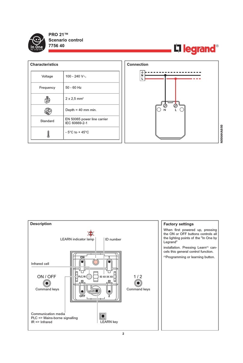
LEGRAND PRO 21 7756 40 User manual

LEGRAND

LEGRAND PRO 21 7756 40 User manual

LEGRAND EMDX3 MI User manual

LEGRAND

LEGRAND EMDX3 MI User manual

LEGRAND BS13 User manual

LEGRAND

LEGRAND BS13 User manual

LEGRAND 5 735 04 User manual

LEGRAND

LEGRAND 5 735 04 User manual

LEGRAND 882 05 User manual

LEGRAND

LEGRAND 882 05 User manual

LEGRAND 675 07 User manual

LEGRAND

LEGRAND 675 07 User manual

LEGRAND 882 04 User manual

LEGRAND

LEGRAND 882 04 User manual

LEGRAND 0 676 94 User manual

LEGRAND

LEGRAND 0 676 94 User manual

LEGRAND On-Q lyriQ AU1001 User manual

LEGRAND

LEGRAND On-Q lyriQ AU1001 User manual

LEGRAND 6338 53 User manual

LEGRAND

LEGRAND 6338 53 User manual

LEGRAND 4 149 29 Instruction Manual

LEGRAND

LEGRAND 4 149 29 Instruction Manual

LEGRAND Bticino H4652 User manual

LEGRAND

LEGRAND Bticino H4652 User manual

LEGRAND LEXIC 074 03 User manual

LEGRAND

LEGRAND LEXIC 074 03 User manual

LEGRAND 0 677 55L User manual

LEGRAND

LEGRAND 0 677 55L User manual

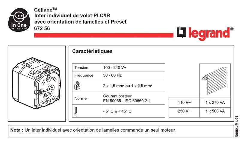
LEGRAND In One Celiane 672 56 User manual

LEGRAND

LEGRAND In One Celiane 672 56 User manual

LEGRAND DPX 1250 User manual

LEGRAND

LEGRAND DPX 1250 User manual

LEGRAND 0 648 73L User manual

LEGRAND

LEGRAND 0 648 73L User manual

LEGRAND 67217 User manual

LEGRAND

LEGRAND 67217 User manual

LEGRAND 7 521 82 User manual

LEGRAND

LEGRAND 7 521 82 User manual

LEGRAND 0 677 23L User manual

LEGRAND

LEGRAND 0 677 23L User manual

LEGRAND Wattstopper ELCU-100 User manual

LEGRAND

LEGRAND Wattstopper ELCU-100 User manual

LEGRAND 4 149 40 Instruction Manual

LEGRAND

LEGRAND 4 149 40 Instruction Manual

Popular Control Unit manuals by other brands

Seitz 14A80 user manual

Seitz

Seitz 14A80 user manual

Wilo RS485 Installation and operating instructions

Wilo

Wilo RS485 Installation and operating instructions

Becker CentralControl CC41 Commissioning Instruction

Becker

Becker CentralControl CC41 Commissioning Instruction

SICK CDB650 operating instructions

SICK

SICK CDB650 operating instructions

Panduit NetKey NKP5E88M Series installation instructions

Panduit

Panduit NetKey NKP5E88M Series installation instructions

MX Options Concentric Petite Fitting instructions

MX

MX Options Concentric Petite Fitting instructions

Clean Water Systems Fleck 2510 Installation & start?up guide

Clean Water Systems

Clean Water Systems Fleck 2510 Installation & start?up guide

Fairchild FSB44104A user guide

Fairchild

Fairchild FSB44104A user guide

PMK ATT10BNCS instruction manual

PMK

PMK ATT10BNCS instruction manual

Tektronix TDS3FFT user manual

Tektronix

Tektronix TDS3FFT user manual

Woodward easYgen Technical manual

Woodward

Woodward easYgen Technical manual

Balluff BNI EIP-502-105-R015 user guide

Balluff

Balluff BNI EIP-502-105-R015 user guide

NXP Semiconductors TWR-LS1021A Getting started

NXP Semiconductors

NXP Semiconductors TWR-LS1021A Getting started

Advantech PCM-3117 Startup manual

Advantech

Advantech PCM-3117 Startup manual

Danfoss MCO 101 manual

Danfoss

Danfoss MCO 101 manual

Moons' Lin Engineering R701P user manual

Moons'

Moons' Lin Engineering R701P user manual

Aventics RV1 operating instructions

Aventics

Aventics RV1 operating instructions

MOTECK CB4M-S user guide

MOTECK

MOTECK CB4M-S user guide

manuals.online logo
manuals.online logoBrands
  • About & Mission
  • Contact us
  • Privacy Policy
  • Terms and Conditions

Copyright 2025 Manuals.Online. All Rights Reserved.

Installation Instructions • Notice ďInstallation • Instrucciones de Instalación
Catalog Number(s) • Numéro(s) de Catalogue • Les Numéros de Catalogue:
Country of Origin: Made in Taiwan • Pays ďorigine: Fabriqué en Taiwan • Pais
de origen: Hecho en Taiwán
1x4 and 1x8 Enhanced Cable Video Modules
Modules vidéo à câble améliorés 1x4 et 1x8
Módulos de video por
cable mejorados 1x4 y 1x8
Doc. #0349 12/14Rev B
VM1000, VM1002
1
2
The Legrand 1x4, and 1x8 Enhanced Cable Video Modules (P/N
VM1000 and VM1002 respectively) are video splitter/combiner
modules specifically designed for today’s two-way broadband cable
networks. They may be used both as combiners to collect video
inputs for amplification and also as part of a video distribution
application.
Les modules vidéo à câble améliorés 1x4 et 1x8 Legrand (n° de réf.
VM1000 et VM1002 respectivement) sont des modules
séparateur/combineur vidéo spécifiquement conçus pour les réseaux
câblés à large bande bidirectionnels actuels. Ils peuvent être utilisés
comme combineurs pour recueillir des entrées vidéo à des fins
d'amplification ainsi que comme partie d'une application de
distribution vidéo.
Los módulos de video por cable mejorado 1x4, y 1x8 de Legrand
(N.° de pieza VM1000 y VM1002 respectivamente) son módulos
divisores/combinadores de video específicamente diseñados para
las redes de cable de banda ancha de dos vías actuales. Pueden
utilizarse como combinadores para recoger entradas de video para
amplificación y también como parte de una aplicación de distribución
de video.
VM1000 = 1x4
VM1002 = 1x8
*AC1007
A. Align tabs on bracket with slots on the rear of the enclosure.
B. Insert tabs by angling bracket away from the back of the enclosure.
C. Rotate the bracket and insert push-pin on bracket into corresponding hole on the rear of the
enclosure. (Plunger must be in a pulled out position for push-pin to engage hole.)
D. Push plunger in to lock bracket in place. Pull on bracket to assure it is locked properly in
place.
A. Alignez les languettes du support avec les fentes à l'arrière du boîtier.
B. Insérez les languettes en penchant le support pour l'écarter de l'arrière du boîtier.
C. Tournez le support et insérez la goupille-poussoir du support dans l'orifice correspondant à
l'arrière du boîtier. (Le poussoir doit être en position sortie pour que la goupille-poussoir
puisse rentrer dans l'orifice.)
D. Enfoncez le poussoir pour verrouiller le support dans cette position. Tirez sur le support pour
vous assurer qu'il est bien verrouillé dans cette position.
A. Alinee las lengüetas del soporte con las ranuras de la parte trasera del gabinete.
B. Inserte las lengüetas alineando el soporte hacia afuera de la parte trasera del gabinete.
C. Gire el soporte e inserte el pasador a presión del soporte en el orificio correspondiente de la
parte trasera del gabinete. (El émbolo debe estar en una posición retirada para que el
pasador a presión encaje en el orificio).
D. Empuje el émbolo para fijar el soporte en su lugar. Tire del soporte para asegurarse de que
esté correctamente fijo en su lugar.
INSTALLATION INSTRUCTIONS
Please read these instructions completely before you begin.
NOTICE D’INSTALLATION
Veuillez lire ces instructions dans leur intégralité avant de
commencer.
INSTRUCCIONES DE INSTALACIÓN
Lea estas instrucciones en su totalidad antes de comenzar.
*AC1007 included, inclus, incluido
VM1000 = 1x4
Combiner,
Combinateur,
Combinador
VM1002 = 1x8
Splitter,
Splitter,
Divisor
860.233.6251
1.877.BY.LEGRAND
www.legrand.us
www.legrand.ca
© Copyright 2014Legrand All Rights Reserved.
© Copyright 201
4Tous droits réservés Legrand.
© Copyright 201
4Legrand Todos los derechos reservados.
Doc. #0349 12/14Rev B
A.Features:
5 - 1000 MHz (1 GHz) - Bi-Directional Splitter.
Auto-seizing F port connectors
6 kV ring wave surge protected for high surge resistance
Digital cable and HDTV approved by most major cable operators
Low intermodulation and 40 dB port-to-port return band isolation
B.Specifications:
Frequency Insertion Loss Isolation Input Return Loss Output Return Loss
5-14 MHz 6.8/9.0/10.8dB 25/25/25dB 22/22/22dB 22/22/22dB
14-40 MHz 6.8/9.0/10.8dB 40/35/40dB 22/22/25dB 38/30/35dB
40-200 MHz 7.0/9.2/10.8dB 35/28/35dB 22/22/22dB 28/25/28dB
200-550 MHz 7.2/9.4/11.0dB 28/26/28dB 22/22/22dB 25/22/25dB
550-750 MHz 7.4/9.6/11.2dB 26/26/26dB 22/22/22dB 22/22/22dB
750-1000 MHz 7.8/10.0/12.0dB 24/24/24dB 22/22/22dB 22/22/22dB
Nominal Impedance: 75 Ohm
F-Connector Type: ANSI/SCTE Compliant Sealed Brass
F-Connector Torque: 30 in. lbs. (max)
Surge Protection: 6 kV Ring Wave Surge per IEEE C62.41 Category A3 Compliant
Second Harmonic: -45 dBmV after 6 kV ring wave surge with a +55 dBmV return input carrier
Operating Temperature:-40° C to 60° C, -40° F to 140° F
3