Stenner ECON FP Series Manual

TO BE INSTALLED BY PROPERLY TRAINED
PROFESSIONAL INSTALLER ONLY. READ
MANUAL & LABELS FOR ALL SAFETY
INFORMATION & INSTRUCTIONS.
ECON FP PUMP SER ES
NSTALLAT ON AND MA NTENANCE MANUAL
PERIS AL IC ME ERING PUMPS SINCE 1957

2www.stenner.comcon FP
Warranty and Service Policy ................................................................. 3
Safety nformation ...................... 4-5, 8, 11, 14, 16, 19-20, 25-29, 31-33
Materials of Construction .................................................................... 6
Accessory Checklist............................................................................. 7
Outputs ............................................................................................... 8
Modes of Operation Description .......................................................... 9
Control Panel Guide...................................................................... 10-11
Pre-Programming Requirements ................................................... 12-13
Program Pump Settings ................................................................ 14-18
nstallation................................................................................... 19-28
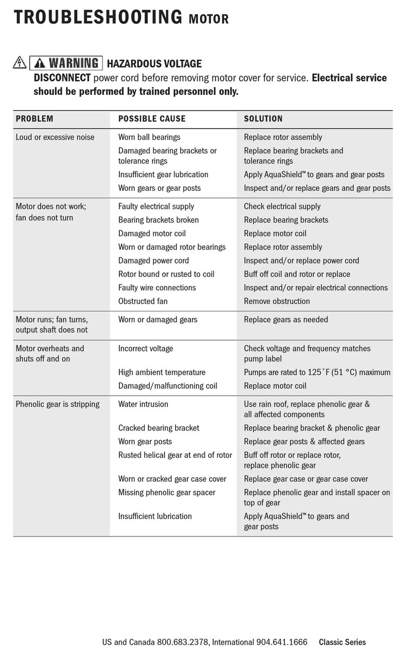
Troubleshooting ............................................................................ 29-31
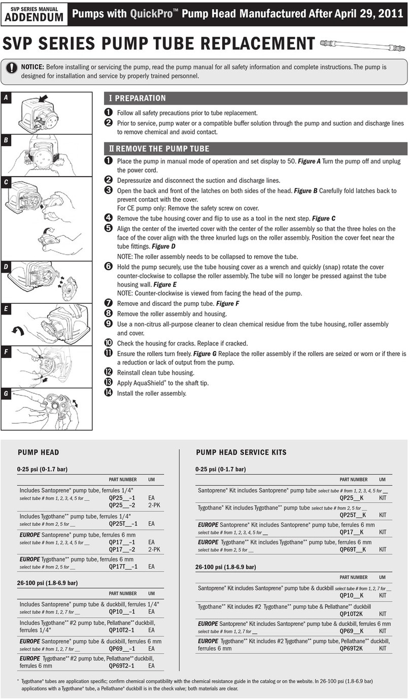
Tube Replacement ........................................................................ 32-34
Exploded View.................................................................................... 35
Parts ................................................................................................. 36
Mounting Template ............................................................................ 37
IMEFP 0614
TABLE OF CONTENTS

L M TED WARRANTY
Stenner Pump Company will for a period of one (1) year from the date of purchase (proof
of purchase required) repair or replace – at our option – all defective parts. Stenner is not
responsible for any removal or installation costs. Pump tube assemblies and rubber
components are considered perishable and are not covered in this warranty. Pump tube
will be replaced each time a pump is in for service, unless otherwise specified. The cost of
the pump tube replacement will be the responsibility of the customer. Stenner will incur
shipping costs for warranty products shipped from our factory in Jacksonville, Florida. Any
tampering with major components, chemical damage, faulty wiring, weather conditions,
water damage, power surges, or products not used with reasonable care and maintained in
accordance with the instructions will void the warranty. Stenner limits its liability solely to
the cost of the original product. We make no other warranty expressed or implied.
RETURNS
Stenner offers a 30-day return policy on factory direct purchases. xcept as otherwise
provided, no merchandise will be accepted for return after 30 days from purchase. To
return merchandise at any time, call Stenner at 800.683.2378 for a Return Merchandise
Authorization (RMA) number. A 15% re-stocking fee will be applied. Include a copy of your
invoice or packing slip with your return.
DAMAGED OR LOST SH PMENTS
Check your order immediately upon arrival. All damage must be noted on the delivery
receipt. Call Stenner Customer Service at 800.683.2378 for all shortages and damages
within seven (7) days of receipt.
SERV CE & REPA RS
Before returning a pump for warranty or repair, remove chemical from pump tube by
running water through the tube, and then run the pump dry. Following expiration of the
warranty period, Stenner Pump Company will clean and overhaul any Stenner metering
pump for a minimum labor charge plus necessary replacement parts and shipping. All
metering pumps received for overhaul will be restored to their original condition. The
customer will be charged for missing parts unless specific instructions are given. To return
merchandise for repair, call Stenner at 800.683.2378 or 904.641.1666 for a Return
Merchandise Authorization (RMA) number.
D SCLA MER
The information contained in this manual is not intended for specific application purposes.
Stenner Pump Company reserves the right to make changes to prices, products, and
specifications at any time without prior notice.
3
USA and Canada 800.683.2378, International 904.641.1666 con FP
WARRANTY AND CUSTOMER SERV CE

4www.stenner.comcon FP
SAFETY NFORMAT ON
Warns about hazards that CAN cause death, serious personal
injury, or property damage if ignored.
ELECTR C SHOCK HAZARD
ELECTR C SHOCK HAZARD:
The pump must only be used with the Class II power supply that is supplied with
the pump.
R SQUE DE CHOC ELECTR QUE:
La pompe ne peut être utilisée qu’avec le bloc d’alimentation de type Classe II
originalement fourni avec celle-ci.
R SK OF ELECTR C SHOCK:
This pump has not been investigated for use in swimming pool or marine areas.
R SQUE DE CHOC ELECTR QUE:
La pompe n’a pas été vérifiée et approuvée pour utilisation sur des applications de
piscine ou autre installation marine.
DO NOT alter the power cord or power supply.
DO NOT use receptacle adapters.
DO NOT use pump with a damaged or altered power cord or power supply. Contact
the factory or an authorized service facility for repair.
HAZARDOUS VOLTAGE:
D SCONNECT power cord before removing motor cover for service. Electrical service
by trained personnel only.
EXPLOS ON HAZARD:
This pump is not explosion proof. DO NOT install or operate in an explosive environment.
R SK OF EXPOSURE:
Potential for burns, fire, explosion, personal injury, or property damage. To reduce risk
of exposure, the use of proper personal protective equipment is mandatory.
R SK OF F RE HAZARD:
DO NOT install or operate on any flammable surface.
R SK OF CHEM CAL OVERDOSE:
To reduce risk, follow proper installation methods and recommendations. Check your
local codes for additional guidelines.
This appliance is not intended for use by persons (including
children) with reduced physical, sensory or mental capabilities, or lack of experience
and knowledge, unless they have been given supervision or instruction to concerning
use of the appliance by a person responsible for their safety.

5
USA and Canada 800.683.2378, International 904.641.1666 con FP
SAFETY NFORMAT ON continued
Warns about hazards that W LL or CAN cause minor personal
injury or property damage if ignored.
PLUMB NG:
Metering pump installation must always adhere to your local plumbing codes and
requirements. Be sure installation does not constitute a cross connection. Check
local plumbing codes for guidelines.
This pump has been evaluated for use with water only.
NOT CE: ndicates special instructions or general mandatory action.
This metering pump is portable and designed to be removable from the plumbing
system without damage to the connections.
Before installing or servicing the pump, read the pump manual for all safety
information and complete instructions. The pump is designed for installation and
service by properly trained personnel.
Installation and product must adhere to all regulatory and compliance codes
applicable to the area.
This is the safety alert symbol. When displayed in this manual or on the
equipment, look for one of the following signal words alerting you to the
potential for personal injury or property damage.
Acceptable for indoor use only.
Pour utilisation à l’intérieur uniquement.
lectrical installation should adhere to all national and local codes. Consult a licensed
professional for assistance with proper electrical installation.
Removing power from recirculation pump must also remove power from pump.
The use of an auxiliary safety device (not supplied), such as a flow switch or sensor,
is recommended to prevent feed pump operation in the event of a recirculation
pump failure or if flow is not sensed.
Point of injection should be beyond all pumps, filters, and heaters.
Maximum temperature = 40°C

6www.stenner.comcon FP
MATER ALS OF CONSTRUCT ON
All Housings
Polycarbonate
Peristaltic ube & Check Valve Duckbill
Santoprene®*, FDA approved
Suction/Discharge ubing & Ferrules
Polyethylene, FDA approved
Weighted Suction Line Strainer
Polypropylene or Type 1 Rigid PVC body with Type 1 Rigid PVC cap, NSF listed; ceramic weight
ube Fittings
Polypropylene, NSF listed
Check Valve Fittings
Type 1 Rigid PVC, NSF listed
Connecting Nuts
Type 1 Rigid PVC or Polypropylene
All Fasteners
Stainless Steel
*Santoprene®is a registered trademark of xxon Mobil Corporation.

7
USA and Canada 800.683.2378, International 904.641.1666
ACCESSORY CHECKL ST
Contents
3 Connecting Nuts 1/4"
3 Ferrules 1/4" or 6 mm Europe
1 Injection Check Valve
1 Weighted Suction Line Strainer 1/4"
1 20' Roll of Suction/Discharge Tubing
1/4" White or UV Black OR 6 mm White Europe
1 Additional Pump Tube
1 Installation Manual
con FP

8www.stenner.comcon FP
Item Number Pump Roller Gallons Gallons Ounces Ounces Pressure
Prefix ube Assembly per Day per Hour per Hour per Minute psi
20PHF F White 4.5 0.19 24.0 0.40 80
20PHG G Black 16.0 0.67 85.3 1.42 80
20PHH H Black 30.0 1.25 160.0 2.67 80
Item Number Pump Roller Liters Liters Milliliters Milliliters Pressure
Prefix ube Assembly per Day per Hour per Hour per Minute bar
20PHF F White 17.01 0.71 708.8 11.8 5.5
20PHG G Black 60.48 2.52 2520.0 42.0 5.5
20PHH H Black 113.40 4.72 4725.0 78.8 5.5
Approximate Maximum Outputs @ 50/60Hz
NOT CE: The information within this chart is solely intended for use as a guide. The output data is an approximation based on
pumping water under a controlled testing environment. Many variables can affect the output of the pump. Stenner Pump
Company recommends that all metering pumps undergo field calibration by means of analytical testing to confirm their outputs.
Approximate Maximum Outputs @ 50/60Hz
NOT : Injection check valve included.
OUTPUTS

9
USA and Canada 800.683.2378, International 904.641.1666 con FP
MODES OF OPERAT ON DESCR PT ON
The con FP is a flow activated pump and will can accept a dry contact signal or a 12-24
VAC/VDC signal from any control equipment that responds to flow. The pump runs at a set
time or a set speed according to the mode of operation selected. The run time or the pump
speed is adjustable from10% to100% in 1% increments. The control panel displays the
modes of operation as SECONDS, AUX L ARY and FLOW SW TCH.
Before programming, review the pre-programming requirements pages 12 to 13, steps A-D.
In the Seconds mode, the pump can receive a dry (non-voltage) contact signal and will run
for a set time in response to receiving the signal. The pump can receive the signal from, for
example,a water meter or control valve that sends a dry contact signal. There is a choice of
five pump operating time ranges and the maximum time is displayed in the control panel;
the run time is adjustable from 10% to 100% in 1% increments.
1 S COND = 0.1 to 1.0
5 S CONDS = 0.5 to 5.0
10 S CONDS = 1.0 to 10.0
20 S CONDS = 2.0 to 20.0
60 S CONDS = 6.0 to 60.0
In the Auxiliary mode, the pump can accept a 12-24 VAC/VDC signal and will run at a set
speed for as long as it receives the signal. The pump speed is adjustable from 10% to
100% in 1% increments. If polarity is reversed when connecting a DC signal to the AUX
input, the pump will not respond to the signal. The pump can receive the signal from a
control valve or another type of control equipment that responds to flow.
In the Flow Switch mode, the pump will accept a dry (non-voltage) contact signal from a
2 wire flow switch and will run at the set speed for as long as it receives the dry contact.
The pump speed is adjustable from 10% to 100% in 1% increments. The connection is not
polarity sensitive (polarity is not an issue when connecting the flow switch wires).
SECONDS (dry contact signal)
AUX L ARY (12-24 VAC/VDC signal)
FLOW SW TCH (dry contact signal)

10 www.stenner.comcon FP
CONTROL PANEL GU DE –BUTTONS
The control panel has a backlit LCD display; when operating it will display the operating
modes and the % setting. The pump is factory pre-set at the lowest settings. The keypad is
locked and in standby mode.
To unlock the keypad, simultaneously press and hold and for 5 seconds. The
keypad will automatically lock if there is no operation for 60 seconds.
Following are the buttons for programming the modes of operation.
To prime the pump or run the pump at full speed, first press & continue to hold ,
then press .
To place the pump in or out of standby, first press & continue to hold , then
press . The pump will not respond to incoming signals when in STBY mode.
To select a mode of operation, first press & continue to hold , then press or
to scroll through the selections. The display will show FLOW SWITCH, AUXILIARY (for
12-24 VAC/VDC), or S CONDS.
After the operational mode is selected, select the percentage setting. First press & continue
to hold , then press or until the desired percentage is reached.
STBY
MODE PR ME
MODE
MODE or
%
MODE
%
MODE %
or
PR ME
STBY
MODE
MODE
MODE
%
MODE
%

11
USA and Canada 800.683.2378, International 904.641.1666 con FP
5 seconds 100%
Keypad locKed
+
++
+
CONTROL PANEL GU DE – ND CATORS
The display has flashing indicators beneath the operating mode and setting. The indicators
are “PRIME”, “S ANDBY”, “SIGNAL”, “PAUSE” and “KEYPAD LOCKED” and represent the
following functions:
PRIME = Prime button is pressed, pump will run full speed
S ANDBY = Standby button was pressed, pump is in standby
SIGNAL = Pump received a signal
PAUSE = Pump received a dry contact to the pause input
KEYPAD LOCKED = After 60 seconds of no keypad operation, the keypad will lock and
the display will show “KEYPAD LOCKED”
5 seconds 100%
pRiMe
Flashing Indicators
Operating Mode Percentage Setting
standby signal pause
Control Panel

12 www.stenner.comcon FP
PRE-PROGRAMM NG REQU REMENTS
Common Chemical Solution Strengths in ppm
Name % ppm
Sodium Hypochlorite 5.25 52,500
6.125 61,250
12.5 125,000
Potassium Permanganate Dissolved at 1/4 lb per gallon 3 30,000
Hydrogen Peroxide 7 70,000
Polyphosphate Dissolved at 1 lb per 10 gallons 1.2 12,000
A. Determine the Maximum System Flow Rate or Well Pump Flow Rate in Gallons
per Minute.
If well pump output is unknown, refer to example below:
Calculate well pump output rate in gallons per minute (gpm).
Determine the output rate by opening a faucet until the well pump turns on.
Immediately turn off the faucet and time how long the well pump runs. Next, measure
the volume of water drawn from the faucet until the well pump turns on again.
volume of water until the pump turns on (gal.) =Well Pump Output Rate (gpm)
how long the pump runs (min.)
B. Determine Solution Strength Percentage and the Dosage Requirement in Parts
per Million.
If osage is unknown, refer to example below:
Calculate required dosage in parts per million (ppm).
Refer to Oxidation Rates below. stimate dosage and include the ppm of
required residual.
Oxidation Rates
For each ppm of ron Manganese Hydrogen Sulfide
Required ppm of Chlorine 12 3
Required ppm of Hydrogen Peroxide 0.5 1 1.5
Before programming the pump, collect or calculate the data in steps A through D then
continue with the instructions for the Seconds, Auxiliary or Flow Switch mode.
2 ppm iron x 1 ppm chlorine = 2
4 ppm hy rogen sulfi e x 3 ppm chlorine = 12
1 ppm chlorine resi ual = 1
Total 2 + 12 + 1 = 15 ppm
Example: To treat a water supply containing
2 ppm iron an 4 ppm hy rogen sulfi e
with a chlorine resi ual of 1 ppm, a osage
15 ppm of chlorine is require .
10 gallons = 5 gpm
2 minutes
Example: After rawing 10 gallons of water,
the well pump took 2 minutes to fill the
pressure tank an stop.

13
USA and Canada 800.683.2378, International 904.641.1666 con FP
C. Calculate Metering Pump Output Requirement in Gallons per Day .
Maximum System Flow Rate (gpm) x Dosage (ppm) x 1440 =Metering Pump Output
Solution Strength ppm*Requirement (gpd)
*Solution Strength % x 10,000 = Solution Strength ppm
D. Reference the chart below to confirm the selected pump’s maximum output
slightly exceeds the pump output requirement calculated in C.
FP Pump (up to 80 psi/5.5 bar)
tem Number Prefix Pump Tube Roller Assembly Maximum Output (gpd)
20PHF F White 4.5
20PHG G Black 16.0
20PHH H Black 30.0
PRE-PROGRAMM NG REQU REMENTS continued

14 www.stenner.comcon FP
1. Calculate the Available Dose Time in Seconds.
The available dose time is the minimum time interval between the water meter
contact closures.
a. 60 Seconds = Maximum System Flow Rate (spg)
Maximum System Flow Rate (gpm)
b. Maximum System Flow Rate (spg)
Water Meter’s contacts per gallon (cpg)* = Available Dose Time (sec.)
*Refer to the water meter model to confirm the contact rate (cpg).
2. Calculate the Pump Operating Time in Seconds.
Pump Output Requirement (gpd) x Available Dose Time (sec.) =Pump Operating
Pump’s Maximum Output (gpd) Time (sec.)
PUMP OPERAT NG T ME EXCEED NG AVA LABLE DOSE
T ME MAY LEAD TO DOS NG ERRORS. To reduce operating time, select a pump with
a higher output or use a stronger solution strength.
3. Calculate the Pump Operating Time Percentage.
Reference the chart to find the pump’s maximum operating time for the formula below.
Pump Operating Time (sec.) x 100 = Pump Operating Time Percentage
Maximum Pump Operating Time (sec.)**
** Value can only be 1, 5, 10, 20, or 60.
Seconds Mode MAX MUM Pump Operating
Time in Seconds
1 S COND 1.0
5 S CONDS 5.0
10 S CONDS 10.0
20 S CONDS 20.0
60 S CONDS 60.0
PROGRAM PUMP SETT NGS
SECONDS MODE (dry contact signal)

15
USA and Canada 800.683.2378, International 904.641.1666 con FP
60 seconds 50%
60 seconds 50%
Keypad locKed
+
++
+
PROGRAM PUMP SETT NGS
SECONDS MODE (dry contact signal) continued
4. Program the Pump Operating Mode and the Pump Operating Time Percentage.
Unlock the Keypad
Press and simultaneously and hold for 5 seconds to unlock the keypad.
Pump Operating Mode
First, press and continue to hold , then press or ; when the display
shows 1, 5, 10, 20 or 60 S CONDS, release both buttons to select based on the
pump operating time determined in #2. The operating mode is now set.
Pump Operating Time Percentage
The pump operating time can be set from 10% to 100% in 1% increments. First,
press and continue to hold , then press or to adjust the pump
operating time percentage determined in #3. When the display shows the desired
percent, release both buttons to select. The percentage is now set.
For example, if the pump is set in the 60 secon s mo e an the setting is 50%, the pump will run for
30 secon s when it receives a signal from the water meter.
MODE
%
xample of control panel set for 50% of 60 seconds.
MODE
%
xample of control panel with keypad locked.

16 www.stenner.comcon FP
PROGRAM PUMP SETT NGS
AUX L ARY (12-24 VAC/VDC signal)
General Guidelines
The host device must have the ability to interface with the pump via a 12-24 VAC/VDC
signal. For typical water softener installation, the controller provides the ability to program
the amount of water that passes through the water softener in gallons per signal (referred
to as Water Volume per Signal in 2a below) and the duration of the signal in seconds
(referred to as Water Softener Chemical Feed Duration in 2b below).
Refer to the specific water softener manual for instructions on how to program the settings
and make the signal connections to the metering pump.
1. Determine the desired water volume (in gallons) that will pass through the water
softener to require the (water softener) controller to send a signal to the metering
pump (e.g. at every gallon).
NOT : Smaller water volume between signals generally allows for more even
chemical dispersion.
2. Calculate the Water Softener Chemical Feed Duration in Seconds.
The water softener chemical feed duration (in seconds) is the programmed amount of
time that the (water softener) controller is continually activating the metering pump
(to dispense chemical).
a. Max System Flow Rate (gpm) = Signals Per Minute
Water Volume per Signal (gallons per signal)
b. 60 Seconds
Signals Per Minute = Water Softener Chemical Feed Duration (sec.)
F THE ACTUAL SYSTEM FLOW RATE EXCEEDS THE MAX MUM
SYSTEM FLOW RATE VALUE USED N THE CALCULAT ON N 2a; THE AVA LABLE
WATER SOFTENER CHEM CAL FEED DURAT ON W LL BE REDUCED AND CAN LEAD TO
DOS NG ERRORS.

17
USA and Canada 800.683.2378, International 904.641.1666 con FP
auxiliaRy 20%
auxiliaRy 20%
Keypad locKed
+
++
+
PROGRAM PUMP SETT NGS
AUX L ARY (12-24 VAC/VDC signal) continued
3. Calculate the Pump Speed Percentage.
Metering Pump Output Requirement (gpd) x 100 = Pump Speed Percentage
Metering Pump Maximum Output (gpd)
4. Program the Pump Operating Mode and the Pump Speed Percentage.
Unlock the Keypad
Press and simultaneously and hold for 5 seconds to unlock the keypad.
Pump Operating Mode
First, press and continue to hold , then press or to scroll through the
modes of operation. When the display shows AUXILIARY, release both buttons to select.
The operating mode is now set.
Pump Speed Percentage
The pump speed can be programmed from 10% to 100% in 1% increments. First, press
and continue to hold , then press or to adjust the speed percentage
determined in #3. When the display shows the desired percent, release both buttons to
select. The percentage is now set.
MODE
xample of control panel with the pump speed set for 20%.
MODE
%
%
xample of control panel with keypad locked.

18 www.stenner.comcon FP
Flow switch 10%
Keypad locKed
+
++
+
PROGRAM PUMP SETT NGS
FLOW SW TCH (dry contact signal)
1. Calculate the Pump Speed Percentage Setting.
Metering Pump Output Requirement (gpd) x 100 = Pump Speed Percentage Setting
Metering Pump Maximum Output (gpd)
2. Program the Pump Operating Mode and the Pump Speed Percentage.
Unlock the Keypad
Press and simultaneously and hold for 5 seconds to unlock the keypad.
Pump Operating Mode
First, press and continue to hold , then press or to scroll through
the modes of operation. When the display shows FLOW SWITCH, release both buttons to
select. The operating mode is now set.
Pump Speed Percentage
The pump speed can be programmed from 10% to 100% in 1% increments. First,
press and continue to hold , then press or to adjust the speed
percentage determined in #1. When the display shows the desired percent, release
both buttons to select. The percentage is now set.
Flow switch 10%
MODE %
xample of control panel set for 10% in Flow switch mode.
MODE
%
xample of control panel with keypad locked.

19
USA and Canada 800.683.2378, International 904.641.1666 con FP
NSTALLAT ON
ADD T ONAL SAFETY NSTRUCT ONS
NOT CE: ndicates special instructions or general mandatory action.
Read all safety hazards before installing or servicing the pump. he pump is
designed for installation and service by properly trained personnel.
Use all required personal protective equipment when working on or near a
metering pump.
Install the pump so that it is in compliance with all national and local plumbing
and electrical codes.
Use the proper product to treat potable water systems, use only additives listed or
approved for use.
Inspect tube frequently for leakage, deterioration, or wear. Schedule a regular pump
tube maintenance change to prevent damage to pump and/or spillage.
Pump is not recommended for installation in areas where leakage can cause
personal injury or property damage.

20 www.stenner.comcon FP
MOUNT PUMP
Select a dry location (to avoid water intrusion and pump damage) above the
solution tank.
NOTE: A mounting template is provided on page 37.
To prevent pump damage in the event of a pump tube leak, never mount the
pump vertically with the pump head up.
DO NOT mount pump directly over an open solution tank. Keep tank covered.
Avoid flooded suction or pump mounted lower than the solution container. Draw
solution from the top of the tank. Pump can run dry without damage. f pump is
installed with a flooded suction, a shut-off valve or other device must be
provided to stop flow to pump during service.
To prevent damage to the pump, verify with a volt meter that the receptacle
voltage corresponds with the pump voltage.
NSTALLAT ON
This manual suits for next models
3
Table of contents
Languages:
Other Stenner Water Pump manuals
Popular Water Pump manuals by other brands

SFA
SFA Sanicondens Mini v02 Operating & installation manual

Hozelock
Hozelock titan 5500 Installation and operating instructions

Oase
Oase AquaMax Eco Classic 9000 C operating instructions

Draper
Draper SWP130A instructions

Rotech
Rotech ANSI Series Installation, operation & maintenance manual

DYI SHENG
DYI SHENG DS20-A-01 operating manual

Aspen Pumps
Aspen Pumps Standard manual

VARO
VARO POWERplus Water POW67904 manual

Mesto
Mesto 3232F Series Instructions for use

BRINKMANN PUMPS
BRINKMANN PUMPS TH11 Series operating instructions

Lafferty
Lafferty 920115 Installation & operation instructions

Clarke
Clarke HSE Series Operating & maintenance instructions