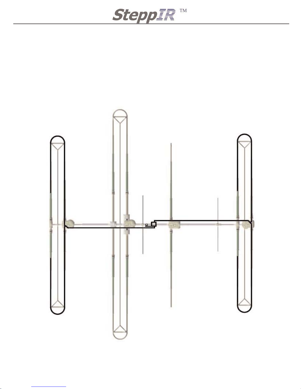
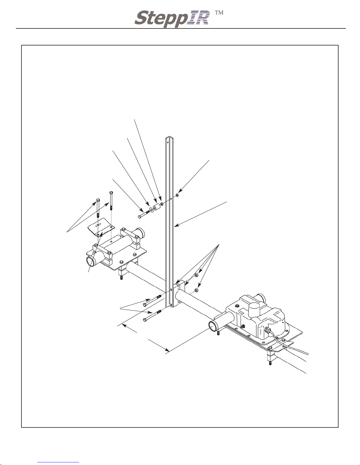
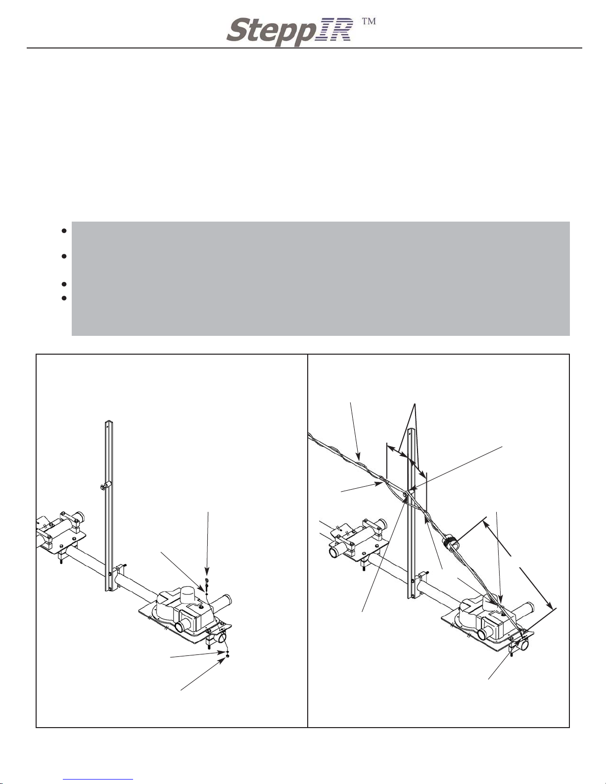
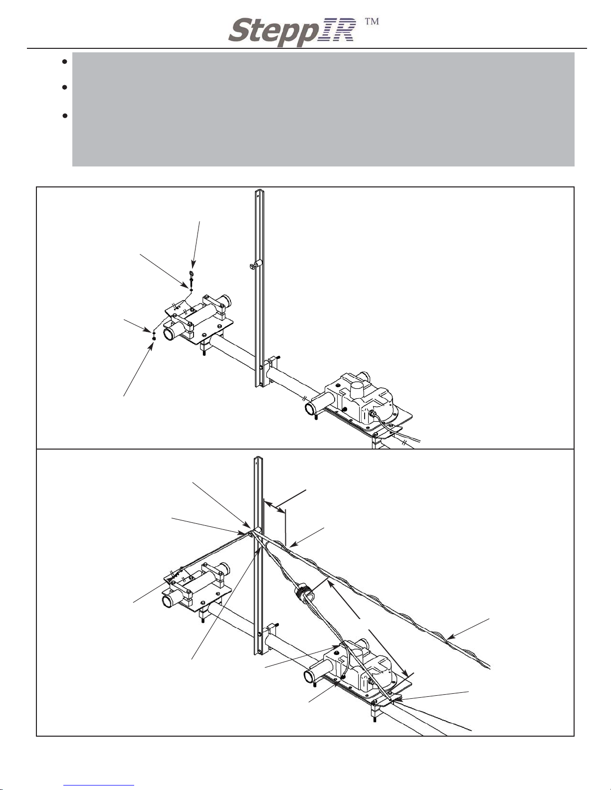
SteppIR 80m Dipole User manual
Other SteppIR Antenna manuals

SteppIR
SteppIR CrankIR Installation guide

SteppIR
SteppIR MonstIR User manual

SteppIR
SteppIR YAGI URBAN BEAM User manual

SteppIR
SteppIR DB42 MonstIR PRO User manual

SteppIR
SteppIR 3 Element Yagi User manual

SteppIR
SteppIR BigIR - MK IV Vertical User manual

SteppIR
SteppIR BigIR User manual

SteppIR
SteppIR SmallIR User manual

SteppIR
SteppIR 3 Element Yagi User manual

SteppIR
SteppIR DB18 Yagi User manual

SteppIR
SteppIR 2 Element Yagi User manual

SteppIR
SteppIR 3 Element Yagi User manual

SteppIR
SteppIR 4 Element Yagi User manual

SteppIR
SteppIR 2E-3E High Wind Kit User manual

SteppIR
SteppIR UrbanBeam Yagi User manual

SteppIR
SteppIR Dream Beam 11 User manual

SteppIR
SteppIR DB18E Yagi User manual

SteppIR
SteppIR SmallIR User manual

SteppIR
SteppIR 2 Element Yagi User manual

SteppIR
SteppIR 4 Element Yagi User manual


Popular Antenna manuals by other brands

DAVIS
DAVIS Windex AV 3160 installation instructions

Belden
Belden Hirschmann BAT-ANT-N-14G-IP23 Mounting instruction

Vtronix
Vtronix YHK Fitting instructions

KVH Industries
KVH Industries TracVision 6 Technical manual

Leica Geosystems
Leica Geosystems GS10 user manual

Sirio Antenne
Sirio Antenne Gain-Master manual


Feig Electronic
Feig Electronic ID ISC.ANTH200/200 Series manual

TERK Technologies
TERK Technologies TV44 owner's manual

TERK Technologies
TERK Technologies SIR3 owner's manual

Directive Systems & Engineering
Directive Systems & Engineering DSE2324LYRMK quick start guide

HP
HP J8999A instructions

MobilSat
MobilSat MSP-S Mounting instructions