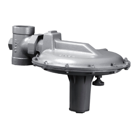
STERIFLOW Mark 96A Series Installation and operating instructions

3170 Wasson Road • Cincinnati, OH 45209 USA
Phone 513-533-5600 • Fax 513-871-0105
steri[email protected] • www.steriowvalve.com
I & M Mark 96A Series
Installation & Maintenance Instructions for
Mark 96A Sanitary Pressure Regulators
Warning: Steriow Sanitary Pressure Regulators must only be used, installed and repaired in accordance with these
Installation & Maintenance Instructions. Observe all applicable public and company codes and regulations. In the
event of leakage or other malfunction, call a qualied service person; continued operation may cause system failure
or a general hazard. Before servicing any valve, disconnect, shut off, or bypass all pressurized uid. Before disas-
sembling a valve, be sure to release all spring tension.
Please read these instructions carefully!
Your Steriow/Jordan product will provide you with long,
trouble-free service if it is correctly installed and main-
tained. Spending a few minutes now reading these in-
structions can save hours of trouble and downtime later.
When making repairs, use only genuine Steriow Valve
parts, available for immediate shipment from the factory.
Introduction
The MK96A is an air loaded sanitary pressure regulating
valve (PRV) remote operated. Traditional sanitary PRV’s
are normally operated and have an adjustment knob
that adds or subtracts tension to a spring. The spring sits
on a platform on top of a diaphragm that is connected
to a stem and valve plug. The opposite, wetted side of
the diaphragm is exposed to the outlet side of the valve
(downstream pressure). Increasing the tension on the
spring moves the diaphragm and stem in the opening
direction, conversely increasing the downstream pres-
sure required to close the valve. Stated another way,
increasing the spring tension, increases the valve’s outlet
pressure set point; and decreasing the spring tension,
decreases the set point pressure.
The typical sanitary PRV installation location is several
feet above grade (clean steam tubing), not easily acces-
sibly because of obstructions, or is un-accessible because
of it’s location in a manufacturing suite. Adjustment of a
manual regulator is time consuming, or nearly impossible
in these installations, The MK96A was invented to solve
this access problem. It uses a remote mounted, adjustable
air pressure source instead of a manually adjusted spring
to apply force to the diaphragm stem and plug. Increas-
ing the air pressure on top of the diaphragm, increase the
valve’s outlet set point pressure, and decreasing the pres-
sure, lowers the outlet pressure set point.
To enable the valve’s operation and adjustment, an air
line is connected to the 1/4” air inlet (22) and an air
regulator* (remotely installed at grade) is used to adjust
the MK96A set point. Alternatively, the MK96A is also
offered with an I/P option, allowing the user to remotely
drive the air pressure with a 4-20 mA signal from distrib-
uted control system (DCS) or PLC logic.
MK96A Ideal Installation
MK 96A Preferred Installation
The valve is designed for sanitary service and it is as-1.
sumed that it will be installed into a clean tubing sys-
tem. Under these conditions, special considerations
to protect the valve such as providing line strainers
at the valve inlet are not necessary.
The regulator should be installed with the inlet (bot-2.
tom of valve) vertical and the outlet horizontal. This
orientation allows unhindered drainage (zero hold-
up). Please note the valve will function in any posi-
tion. Contact factory for other possible orientations.
Steam regulators are best located at the highest 3.
point in the piping with the take-off out of the top of
the steam header. This will minimize the possibility of
retained water in the regulators ow stream.
For best control, 3’-0” straight sections of pipe 4.
should be installed on either side of the regulator to
insure a non-turbulent ow prole.
Use caution in tightening commercial sanitary 5.
ttings. Over-tightening can cause the gasket to
extrude into the ow passage.
6
31
2
4
1
7
1
1
5
Condensate Return Line
R
1 Shut-off Valve
2 Pressure Gauge
3 Steriow Regulator
4 Relief Trap
6 Air Signal
7 Steam Separator
By-Pass Line
T
* air regulator must be a self-relieving type

Clean-In-Place/Steam-In-Place
To perform this procedure, the valve is held in the open
position by applying an air load greater than the CIP/SIP
pressure.
Disassembling Valve
Insure that the valve is not pressurized by following 1.
the Caution at the beginning on the Maintenance
section.
Remove the airload.2.
Remove the actuator (4) by removing the hex bolts (17).3.
Remove the hex jam nut (16), cylinder (14) and lock-4.
washer (15). Caution- beware of spring compression.
Remove the spring and adapter (3).5.
Remove the spacer (11), upper diaphragm plate 6.
(10), and diaphragm (9) from the stem (5). Remove
the lower diaphragm plate (8) and o-rings (19), (20)
where applicable.
Remove the stem (5) from the bottom (inlet) of the 7.
body (1).
Preparing Valve For Assembly
All parts should be cleaned and examined. Damaged
parts should be replaced.
All O-rings should be lubricated with any lubricant that is
compatible with both your process and the o-ring mate-
rial. EPDM o-rings must not be exposed to mineral oil
as it will cause them to swell and make them difcult to
install.
If possible, install a relief valve downstream from the 6.
regulator. Set at about 30% above the control point of
the regulator.
In gas or vapor service, select outlet piping that is at 7.
least one pipe size larger than the inlet.
Operate the regulator within its pressure and temper-8.
ature rating as stamped on the valve nameplate.
If using an air regulator with your MK96A, install a 9.
1/4” tube tting into the 1/4” FNPT air inlet (22) on
the top of the MK96A. Connect an appropriate length
of 1/4” tubing (following local best practice) to the
tube tting and connect the other end to the air pres-
sure regulator at an accessible grade location. Follow
the instructions that come with your air regulator for
proper installation, operation and maintenance.
If using an I/P with your MK96A, connect the I/P air 10.
outlet directly to the MK96A inlet using a threaded
Hex nipple and connect the air line to a tube tting on
the I/P inlet connection. Note: Follow local electrical
code classications and best practice, and make sure
the I/P you have selected has the proper NEMA or IS
rating classication. If not, an alternative might be to
locate the I/P in the nearest Instrumentation/Electri-
cal cabinet with the proper classication. Regardless,
make sure you follow the installation, operation and
maintenance instructions that come with your I/P, and
follow all local best practices, and electrical codes
with regard to wiring and commissioning.
MK96A Start-Up
Fully open the process line block valve downstream 1.
of the regulator using manual air load regulator.
Slowly open the inlet block valve at the regulator 2.
inlet.
Slowly open and close the downstream block valve 3.
several times; this will stroke the valve and conrm
satisfactory operation.
With both block valves open, slowly increase the 4.
airload regulator’s air signal to increase downstream
pressure until it reaches the desired MK96A value.
If using an air regulator with your MK96A, follow 5.
steps 1-3 above. With both block valves open, slowly
increase the dome air signal by adjusting the air
regulator knob (following adjustment instructions in
air regulator installation manual) until the process
pressure downstream of the MK96A reaches the
desired value. Record the air regulator set point in
appropriate documents, or in the control system
information database.
If using an I/P with your MK96A, follow steps 1-3 6.
above. With both block valves open, slowly increase
the dome air pressure to the MK96A inlet by driv-
ing the I/P’s mA input to a value that produces the
desired MK96A outlet pressure. Record the mA set
point value for the PLC, or DCS programmer in the
proper document or in the control system informa-
tion database. Note: Most DCS or PLC HMI programs
allow for manual override of an output signal (manu-
ally adjust 4-20 mA output). If that is not possible,
the I/P wiring (most are two wire devices) can be
disconnected, and a process loop calibrator can be
used to articially drive the I/P to the desired output.
Maintenance
Caution: Make certain that there is no pressure in the
valve before loosening any ttings or joints. The fol-
lowing steps are recommended:
Close the regulator inlet block valve.1.
Allow pressure to bleed off through downstream 2.
piping. Do not attempt to reverse the ow through
the valve by bleeding pressure from the regulator
outlet to the inlet side.
When the upstream and downstream pressure 3.
gauges indicate that all pressure has been removed
from the system, remove the airload or disconnect
the I/P following the devices maintenance manual.
The valve can now be serviced.
Note: refer to the drawing at the end of this document
for description and proper orientation of parts.
-2-

Assembling Valve
Install stem (5) into the body (1).1.
Lubricate o-ring (19) and install into the groove on the 2.
stem (5). Install lower diaphragm plate (8) onto the
stem (5). Lubricate o-ring (20) if so required and in-
stall into the groove in the lower diaphragm plate (8).
Install diaphragm (9) onto stem (5). 3.
Install upper diaphragm plate (10) onto stem (5).4.
Install spacer (11) onto stem (5).5.
Center diaphragm (9) onto body (1). Install adapter 6.
(3) onto body (1). The adapter (3) should engage the
pilot diameter on the body (1). Lubricate o-ring (21)
and install into groove on adapter (3).
Install the spring (18) and lockwasher (15) onto the 7.
stem (5).
Install cylinder (14) onto stem (5).8.
Install hex jam nut (16) onto stem (5) and tighten; ap-9.
ply Loctite No. 290 to the threads to lock joint.
Secure actuator (4) to the body (1). Hand tighten the 10.
hex bolts (17).
Torque hex bolts (17) to 200 in-pounds (17 foot 11.
pounds).
-3-
For soft seated valves: clean threads on the stem (5) and
on the retainer (7) with Loctite primer “T”. Allow to dry.
Install new soft seat (6) on retainer (or onto stem when
application on low ow versions). Apply Loctite No. 620
to threads and thread the retainer (7) onto the stem (5).
Tighten until the screw threads bottom out. Allow to cure.
Troubleshooting
Erratic Control
Oversizing causes cycling and hunting, and reduces •
the rangeability of the valve. Make certain that your
sizing is correct.
Steam traps may require maintenance.•
Safety valve may be defective.•
Valve seat in MK 96A may be defective - Inspect •
for damage and replace stem (5) and/or body (1) if
necessary.
Valve plug in Mark 96A may not be moving freely. •
Inspect bushing (12) and replace if required.
Downstream Pressure Build-up
Valve seat in Mark 96A may be defective - replace •
stem (5) and/or body (1).
Valve plug in Mark 96A may not be moving freely. •
Inspect bushing (12) and replace is required.
Diaphragm (9) in Mark 96A may have failed; replace •
diaphragm if necessary.
Cannot Maintain Regulated Pressure
Piping may be blocked or inadequately sized.•
Inlet pressure may be set too low.•
Airload may be too low; check setting•
Valve may be undersized for required ow; make •
certain that your sizing is correct.

Cross Section View
3170 Wasson Road • Cincinnati, OH 45209 USA
Phone 513-533-5600 • Fax 513-871-0105
steri[email protected] • www.steriowvalve.com
Bulletin IM-MK96A-0308
15
16
11
14
13
20
5
10
12
9
21
4
6
7
1
3
8
18
19
17
Item No. Description Quantity
1 Body 1
3 Adapter 1
4 Actuator 1
5 Stem 1
6 Seat 1
7 Seat Retainer 1
8 Lower Diaphragm Plate 1
9 Diaphragm 1
10 Upper Diaphragm Plate 1
11 Spacer 1
12 Bushing 1
13 Gland 1
14 Cylinder 1
15 Washer 1
16 Jam Nut 1
17 Bolt 8
18 Spring 1
19 O-Ring, Stem 1
20 O-Ring, Lower Diaphragm Plate 1
21 O-Ring, Adapter 1
22 1/4” NPT Air Inlet 1
22
Other STERIFLOW Controllers manuals
