manuals.online logo
Brands
  1. Home
  2. •
  3. Brands
  4. •
  5. Berker
  6. •
  7. Controllers
  8. •
  9. Berker 75341002 Guide

Berker 75341002 Guide

Shutter/blind actuator 1gang 6A flush-
mounted
75341002
Technical
Documentation
© Berker GmbH & Co KG 2005 Version: 17.08.2005 Part 7
(Subject to prior change) 75341002.doc Seite: 1 / 35
Design: FM (flush-mounted type)
Article-no.: 7534 10 02
ETS search path: Shutter / Shutter / Shutter/blind actuator 1gang 6A flush-mounted
Functional description:
The shutter/blind actuator receives telegrams from sensors via the Instabus and controls a shutter or blind motor
with its output. Both travel directions are mechanically interlocked. With sun protection or positioning telegrams, the
actuator offers moreover the possibility of moving shutters, blinds and slats into any desired position. On reception of
a storm warning, the actuator is capable of moving shutters or blinds into a predefined safety position and to lock
them up in this position.
The device is equipped with two extension inputs which - depending on parameterization - can act directly on the
shutter/blind output (local control / double-sided push-button principle) or alternatively as binary inputs on the
Instabus. The connected potential-free switch or push-button contacts are sensed against a common reference
potential at the shutter/blind actuator. As a binary input, the device can transmit telegrams for switching or dimming,
for shutter/blind control or for value transmitter applications (dimming value transmitter, light scene extension).
Connecting 230 V signals or other external voltages to the extension inputs is not permitted.
The shutter/blind actuator is supplied from the Instabus and needs therefore no additional external power supply.
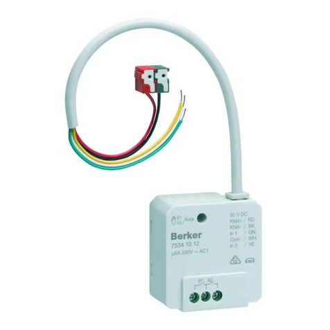
Illustration: Dimensions: Controls:
B
µµ
PKBNBK
L
EIB+ / RD
EIB- / BK
1 / GN
com / WH
2 / YE
com / BN
A
Prog.
C
Ø: 53 mm
Height (H): 28 mm
A Low-voltage connecting wires
red (RD): bus (+)
black (BK): bus (-)
green (GN): extension input 1
white (WH): reference potential (com)
yellow (YE): extension input 2
brown (BN): reference potential (com)
B Load connection wires
black (BK): L (phase connection)
brown (BN): (travel direction UP)
magenta (PK): (travel direction DOWN)
C: Programming button / LED (red)
Technical data
Type of protection: IP 20
Safety class: III
Mark of approval: KNX / EIB
Ambient temperature: -5 °C ...+45 °C
Storage / transport temperature: -25 °C ...+70 °C (storage above +45 °C results in s horter lifetime)
Mounting position: any
Minimum spacings: none
Type of fastening: e.g. placing into deep flush-mounting box (∅60 mm x 60 mm)
Instabus EIB supply
Cable type: YY 6 x 0.6 mm; red: bus (+) / black: bus (-)
Voltage: 21 – 32 V DC SELV
Power consumption: typically 150 mW
Connection: approx. 33 cm ready-made; connecting terminal (0.6 – 0.8 mm)
External supply ---
Response to voltage failure: Outputs: depending on parameterization
(cf. "parameter description")
Inputs: no reaction
Response to bus voltage return: Outputs: depending on parameterization
(cf. "parameter description")
Inputs: depending on parameterization
(cf. "parameter description")
Shutter/blind actuator 1gang 6A flush-
mounted
75341002
Technical
Documentation
© Berker GmbH & Co KG 2005 Version: 17.08.2005 Part 7
(Subject to prior change) 75341002.doc Seite: 2 / 35
Input:
Number: 2 (depending on parameterization either as extension inputs for
button local control of the actuator or as independent binary inputs
acting on the bus)
Cable type: YY 6 x 0.6 mm
green: extension input 1
white: reference potential (com)
yellow: extension input 2
brown: reference potential (com)
Cable length: approx. 33 cm ready-made, extendible to 5 m max.
Scanning voltage: approx. – 19 V DC referred to "com"; continuous signal
Loop resistance: max. 2 kOhm for safe "1" signal detection (rising edge)
Output:
Number: 1
Cable type: 3 x H05 V-K 1.5 mm² with ferrules
Cable length: approx. 20 cm ready-made
Switch type: 1 change-over contact + 1 make contact,
potential-free relay contacts (µ-contact), bistable
Switching voltage: 230 V AC; 50 / 60 Hz
Switching capacity: max. 1 motor 1,000 VA
Connecting diagram: Terminals:
Load connection:
M
L1
L2
L3
N
µµ
PKBNBK
L
EIB+ / RD
EIB- / BK
1 / GN
com / WH
2 / YE
com / BN
Prog.
Shutter/blind actuator 1gang 6A flush-
mounted
75341002
Technical
Documentation
© Berker GmbH & Co KG 2005 Version: 17.08.2005 Part 7
(Subject to prior change) 75341002.doc Seite: 3 / 35
Connecting diagram: Terminals:
Bus connection and connection of extensions:
COM
COM
1
2
U = approx. -19 V
com
U
COM
U
COM
+ red
- black
green
white
yellow
brown
EIB / KNX
input 1
input 2
A spacing of 4 mm minimum between extra low-voltage lines (bus and extension inputs) and the load lines (230 V)
must be ensured (see fig. A).
It is recommended to install the shutter/blind actuator in two interconnected flush-mounting boxes (see fig. B). One
of the boxes (A) can accomodate besides the bus and extension connections also a series switch (C), whereas the
other box (B) accomodates the shutter/blind actuator and the 230 V terminals. The 6-wire connecting cable (D) is
led through the box junction.
230 V
Bus/Com/1,2
min. 4 mm
Fig. A
A
230 V
B
C
D
µ
µ
GYPKBK
L 1 2
Fig. B
Hardware information
•Never connect the mains voltage (230 V) or other external voltages to the extension inputs. Connecting an
external voltage endangers the electrical safety of the entire KNX/EIB system (SELV / no electrical insulation).
Persons may be put at risk and devices and installations may suffer irreparable damage.
•Make sure during the installation that there is always sufficient insulation between the mains voltage and the bus or
the extensions. A minimum spacing of 4 mm must be ensured between the bus/extension wires and the mains
wires.
•Non-used wires of the 6-wire connecting cable must be insulated with respect to one another and with respect to
external voltages.
•To avoid EMC disturbances, the lines to the inputs should not be laid parallel to lines and cables carrying mains
voltage.
•If motors are to be connected in parallel to an output, it is absolutely indispensable to observe the corresponding
instructions of the motor manufacturers to avoid irreparable damage to the motors. If necessary, use
supplementary isolating relays.
•Use only shutters or blinds with end position limit switches (mechanical or electronic). The limit switches of the
motors connected must be checked for correct adjustment.
Shutter/blind actuator 1gang 6A flush-
mounted
75341002
Technical
Documentation
© Berker GmbH & Co KG 2005 Version: 17.08.2005 Part 7
(Subject to prior change) 75341002.doc Seite: 4 / 35
Software description
ETS search path:
Shutter / Shutter / Shutter/blind actuator 1gang 6A flush-mounted
ETS symbol:
1
PEI Type 00
Hex
0
Dez
No adapter used
Applications:
No.
Short description: Name: Version:
1 Single-channel control of a motor with safety function and sun
protection. Two additional extension inputs. Shutter / blind, 2 inputs 207301 0.1
Application: 1. Shutter / blind, 2 inputs 207301
Executable from mask version: 1.2
Number of addresses (max): 26 dynamic table handling Yes No 
Number of assignments (max): 27 maximum length of table 53
Communication objects: 11
Objects for the binary inputs (extension inputs), if acting on the bus:
Function: no function (for all 2 inputs
2
)
No further input objects
Function: "Switching" (for all 2 inputs
2
)
Object Function Name Type Flag
1 - 2 Switching object X.1 (X = 1 to 2) Input 1 – Input 2 1 bit C, W, T, (R)
1
9 - 10 Switching object X.2 (X = 1 to 2) Input 1 – Input 2 1 bit C, W, T, (R)
1
Function: "Dimming" (for all 2 inputs
2
)
Object Function Name Type Flag
1 - 2 Switching Input 1 – Input 2 1 bit C, W, T, (R)
1
9 - 10 Dimming Input 1 – Input 2 4 bit C, T, (R)
1
Function: "Shutter/blind" (for all 2 inputs
2
)
Object Function Name Type Flag
1 - 2 Short operation (STEP) Input 1 – Input 2 1 bit C, T, (R)
1
9 - 10 Long operation (MOVE) Input 1 – Input 2 1 bit C, T, (R)
1
Function: "Value transmitter" (Function: Dimming value transmitter for all 2 inputs
2
)
Object Function Name Type Flag
1 - 2 Value Input 1 – Input 2 1 byte C, T, (R)
1
Function: "Value transmitter" (Function: Light scene extension with / without storage function for all 2 inputs
2
)
Object Function Name Type Flag
1 - 2 Light scene extension Input 1 – Input 2 1 byte C, T, (R)
1
Function: Disable (for all 2 inputs
3
)
Object Function Name Type Flag
17 - 18 Disable Input 1 – Input 2 1 bit C, W, (R)
1
1
: Objects marked (R) permit read-out of the object status (set R flag).
2
: The "No function", "Switching", "Dimming", "Shutter/blind" and "Value transmitter" functions can be selected per
input. The names of the communication objects and the object table (dynamic object structure) will change
accordingly.
3
: A disable function is not available if the inputs are parameterized for "No function"
Shutter/blind actuator 1gang 6A flush-
mounted
75341002
Technical
Documentation
© Berker GmbH & Co KG 2005 Version: 17.08.2005 Part 7
(Subject to prior change) 75341002.doc Seite: 5 / 35
Objects for the output:
Function: Output
Object Function Name Type Flag
0 Short operation (STEP) Shutter/blind output 1 bit C, W, (R)
1
4 Long operation (MOVE) Shutter/blind output 1 bit C, W, (R)
1
Function: Safety function
Object Function Name Type Flag
12 Safety function Safety 1 1 bit C, W, (R)
1
13 Safety function Safety 2 1 bit C, W, (R)
1
Function: Sun protection function
Object Function Name Type Flag
14 Sun protection function Sun protection 1 bit C, W, (R)
1
1
: Objects marked (R) permit read-out of the object status (set R flag).
Object description
Objects for the binary inputs (extension inputs):
1 – 2 Switching object X.1: 1-bit object for transmitting switching telegrams (ON, OFF)
(1
st
switching object)
9 – 10 Switching object X.2: 1-bit object for transmitting switching telegrams (ON, OFF)
(2
nd
switching object)
1 – 2 Switching: 1- bit object for transmitting switching telegrams (ON, OFF) for the
dimming function
9 – 10 Dimming: 4-bit object for relative brightness variation between 0 and 100 %
1 – 2 Short operation (STEP): 1-bit object for STEP operation of a shutter or blind
9 – 10 Long operation (MOVE): 1-bit object for MOVE operation of a shutter or blind
1 – 2 Value: 1-byte object for transmitting value telegrams (0 - 255)
1 – 2 Light scene extension
1-byte object for recalling and storing light scenes (1 - 64)
17 – 18 Disable: 1-bit object for disabling individual binary inputs
(polarity parameterizable)
Objects for the output:
0 Short operation (STEP): 1-bit object for STEP operation of a shutter / blind
4 Long operation (MOVE): 1-bit object for MOVE operation of a shutter / blind
12 Safety function: 1-bit object for receiving an alarm or safety message (safety 1)
(polarity parameterizable)
13 Safety function: 1-bit object for receiving an alarm or safety message (safety 2)
(polarity parameterizable)
14 Sun protection function: 1-bit object for activating the sun protection function(s)
(polarity parameterizable)
Shutter/blind actuator 1gang 6A flush-
mounted
75341002
Technical
Documentation
© Berker GmbH & Co KG 2005 Version: 17.08.2005 Part 7
(Subject to prior change) 75341002.doc Seite: 6 / 35
Scope of functions
Inputs:
General
•Mode of functioning of the inputs parametrizable:
- function as extension inputs for double-sided actuation of button acting directly on shutter/blind output
(input 1 output UP / input 2 output DOWN) (state-of-delivery setting)
- function as general binary inputs acting separately on the bus
Function as binary inputs to the bus:
•Switching, dimming, shutter/blind and value transmitter functions freely assignable to the max. 2 inputs
•Disable object for disabling of individual inputs (polarity of disable object presettable)
•Delay on return of bus voltage and debouncing time centrally adjustable
•Response to bus voltage return separately parameterizable for each input
•Telegram rate limitation generally parameterizable for all inputs
Switching function
•Two independent switching objects available for each input (switching commands individually parameterizable)
•Command for rising and falling edge individually adjustable (ON, OFF, TOGGLE, no reaction).
•Independent cyclical transmission of switching objects depending on edge or on object value selectable.
Dimming function
•Single-sided and double-sided actuation
•Time between dimming and switching and dimming step width presettable
•Telegram repetition and stop telegram transmission possible
Shutter/blind function
•Command for rising edge adjustable (no function, UP, DOWN, TOGGLE)
•Operation concept parameterizable ("step - move – step" resp. "move – step")
•Time between STEP and MOVE operation presettable (only with "step - move - step")
•Lamella (slat) adjustment time presettable (time during which a "MOVE" command can be terminated by
releasing a push-button on the input)
Value transmitter and light scene extension functions
•Edge (push-button as n.o. contact, push-button as n.c. contact, switch) and value for edge parameterizable
•Value change in push-button mode possible with long press on the button for value transmitter
•In light scene extension with storage function, a light scene can be stored withous preceding recall
Output:
•One channel for a shutter / blind motor
•Type adjustable (shutter or blind)
•Switch-over delay during travel direction change adjustable
•Priority assignment to incoming telegrams parameterizable for sun protection and parameterize (STEP / MOVE)
•Automatic sun protection function for brightness-dependent moving of a shutter or blind into a parameterized
position
•Safety function with cyclical checking and assigning to shutter or blind channels
•Movement into parametrizable limit position on reception of safety message
•Response to failure and return of bus voltage adjustable
Shutter/blind actuator 1gang 6A flush-
mounted
75341002
Technical
Documentation
© Berker GmbH & Co KG 2005 Version: 17.08.2005 Part 7
(Subject to prior change) 75341002.doc Seite: 7 / 35
Functional description of the inputs
Mode of functioning of the inputs
The shutter/blind actuator is equipped with two extension inputs which - depending on parameterization - can act
directly on the shutter/blind output (local control / double-sided button principle) or alternatively as binary inputs on
the Instabus.
In the state as delivered (unprogrammed actuator), the extension inputs act directly on the shutter/blind output. This
means that the actuator can be commissioned and operated already 'on site' simply by connecting the bus voltage
and without further sensors.
•Inputs acting on shutter/blind output
The extension inputs act like an external sensor and with the predefined times for STEP and MOVE operation only
internally directly on the shutter/blind output. In accordance with the double-sided operation principle, input 1
controls the UP direction and input 2 the DOWN direction. In acc. with the 'step-move-step' operating concept, the
relay outputs react as follows:
Input Contact at input Actuation * Relay switching state
1 closed (rising edge) short STEP operation UP / Stop
long MOVE operation UP
open (falling edge) --- no reaction or stop **
2 closed (rising edge) short STEP operation DOWN / Stop
long MOVE operation DOWN
open (falling edge) --- no reaction or stop **
*: The time after which a MOVE operation is executed is fixed at approx. 520 ms. The lamella (slat)
adjustment time is approx. 2.6 s.
520 ms 2.6 s
contact reopened =
stop
STEP-
operation MOVE-
operation
contact closed
t
**: If the contact at the input is reopened before the MOVE operation has been started, only the STEP
operation is completely executed. If - after starting of the MOVE operation - the contact at the input
is being reopened during the slat adjustment time, the actuator will stop the shutter/blind output.
There is no response after opening of the contact.
For direct action, the extension inputs do not have parameters of their own so that the parameter cards for the
inputs are not available. The last selected extension signal is always the one that is executed. The time for STEP
operation of the shutter/blind output should not be less than 520 ms.
After return of bus voltage, the actuator responds to changes of the extension signal state only after the time
parameterized for the "Delay on return of bus voltage" has elapsed.
During the delay, pulse edges or signals present at the inputs are not evaluted and disregarded. The time of delay
is generally parameterized for all inputs and also for the outputs.
•Inputs acting separately on bus
The inputs of the shutter/blind actuator act independently of the shutter/blind output and separately on the Instabus
KNX/EIB. Depending on parameterization, the functions "Switching", "Dimming", "Shutter/blind" or "Value
transmitter" can be selected for each input (cf. "Parameter description"). When "No function" is selected, the
corresponding input is deactivated.
When the "Shutter/blind" setting is selected, the extension objects can be combined via group addresses with the
objects of the shutter/blind outputs. The actuator can thus be controlled via its own inputs even if the extension
signals are set for acting on the bus (e.g. group control of several actuators).
The functional description of the inputs on the following pages is valid only if the extensions are set for acting on the
bus.
Shutter/blind actuator 1gang 6A flush-
mounted
75341002
Technical
Documentation
© Berker GmbH & Co KG 2005 Version: 17.08.2005 Part 7
(Subject to prior change) 75341002.doc Seite: 8 / 35
Dimming value transmitter: change by means of long key press
In the event of dimming value transmitter parameterization, the value to be transmitted can be changed by means of
a long key-press (> 5 s) if the the value is to be transmitted on the rising or the falling edge. In this case, the
programmed value is increased by the parameterized step width and transmitted. After releasing of the input contact,
the value last transmitted remains stored. On the next long key-press, the direction of value change is reversed.
Example:
Value (0...255) 17
Step width (1...10) 5
time
edge at input
value change
value variation direction
change
5 s
time
value = 17 17
17 2 0 0 2 7 12 17
time between
two telegrams
> 5 s
< 5 s
bus
telegram
0
12 7
value change
no further change
minimum value reached
Important:
- During value variation there is no overrun and no underrun. When the maximum (255) resp. the minimum (0) value
is reached, no more telegrams are transmitted.
- To ensure that the concerned lighting switches off or on with the max. value during value variation, the limit values
(values "0" resp. "255") are always transmitted when the limits of the variation range are reached. This is also the
case when the parameterized step width does not directly account for these values (cf. example above: step width
= 5; value "2" is transmitted, thereafter value "0").
To ensure that the original starting value can be set again during a new change (change of variation direction), the
first value jump will not correspond to the preset step width (cf. example above: step width = 5; value "0" is
transmitted, thereafter values "2", "7" etc.).
- When values are changed, the newly set values are stored in the RAM.
After a bus voltage failure or a bus reset, the changed values will be replaced by the values originally
parameterized in the ETS.
Shutter/blind actuator 1gang 6A flush-
mounted
75341002
Technical
Documentation
© Berker GmbH & Co KG 2005 Version: 17.08.2005 Part 7
(Subject to prior change) 75341002.doc Seite: 9 / 35
Light scene extension with / without storage function
In a parameterization as light scene extension without storage function it is possible to recall a light scene. In case of
a rising edge, a falling edge or a rising and a falling edge, the parameterized light scene number is transmitted
immediately.
In a parameterization as light scene extension with storage function it is possible to generate a storage telegram
depending on the light scene to be transmitted. A long actuation of the n.o. contact (rising edge) or of the n.c. contact
(falling edge) causes the corresponding storage telegram to be transmitted. In this case, the time for a long press is
parameterizable (however not below 5 s). After a short press < 1 s, the parameterized light scene number (without
storage telegram) is transmitted. If the actuation is longer than 1 s, but shorter than 5 s, no telegram will be
transmitted at all. In addition, it is possible to transmit only a storage telegram without preceding light scene recall. In
this case, the "Storage function only" parameter must be set to "YES".
Examples for light scene extension with storage function:
1.) Storage function only = NO
2.) Storage function only = YES
time
time
bus
telegram
light-scene
storage
storage
< 1 s 1 s to 3 s
5 s
edge at input
undefined input
no telegram
light-scene
recall
time
Bus-
telegramm
light-scene
storage
light-scene
storage light-scene
storage light-scene
storage
1.)
2.)
light-scene
recall
Storage function only = NO:
If a rising or a falling edge is detected at the input (depending on parameterization), the timer is started. If the key is
released within the first second, the corresponding light scene is recalled immediately. If the key is pressed longer,
the storage telegram is transmitted after 5 s.
Storage function only = YES:
The storage telegram is transmitted immediately after detection of the corresponding edge.
Shutter/blind actuator 1gang 6A flush-
mounted
75341002
Technical
Documentation
© Berker GmbH & Co KG 2005 Version: 17.08.2005 Part 7
(Subject to prior change) 75341002.doc Seite: 10 / 35
Response to return of bus voltage
It is possible to define separately for each input whether a reaction or what kind of reaction is to take place on return
of bus voltage so that a defined telegram can be transmitted to the bus depending on the input signal or by forced
control.
The defined reaction takes place only after the parameterized "Delay on return of bus voltage" has elapsed.
While the delay is active, any edges or signals present at the inputs are not evaluated and disregarded. The delay is
generally parameterized for all inputs and also for the outputs.
It is possible to parameterize a general telegram rate limitation. In this case, no telegram is transmitted within the first
17 s after bus voltage return.
It should be noted that the parameterized "Delay on return of bus voltage" is active also during this time and that the
parameterized reaction on bus voltage return is not executed if the delay elapses within the first 17 seconds.
Disable function
Each input can be independently configured for a certain reaction at the beginning or at the end of disable. It is also
possible to parameterize the input for "No reaction". Only in this case will dimming or shutter control procedures or
value changes in progress before activation of the disable function continue to be executed until the end when
disable is active. In all other cases, the parameterized command will be transmitted immediately at the beginning of
disable. During an active disable, edges or signals at the corresponding inputs are not evaluated.
Updates on disable objects (disable or enable) will always lead to the transmission of the corresponding command
parameterized for "the beginning resp. the end of disabling".
During an active disable, no cyclical transmission takes place via the disable input.
If cyclical transmission did take place before activation of the disable function, no cyclical transmission will take place
anymore at the end of disable when "No reaction" is parameterized. In this case, the object value will again be
transmitted cyclically only after an update on the switching object. In all other cases, the object value will again be
transmitted cyclically after the end of disable.
Cyclical transmission
The object value transmitted is always the object value internally or externally followed up in the switching objects.
For this reason, the object value is transmitted cyclically even if "No reaction" is assigned to a rising or a falling edge.
Cyclical transmission takes place also directly after the return of bus voltage, if the parameterized value of the
telegram after bus voltage return corresponds to the object value parameterization for cyclical transmission. If
telegram rate limitation is enabled, cyclical transmission will take place at the earliest after 17 seconds.
During an active disable, no cyclical transmission takes place via the disabled input.
Shutter/blind actuator 1gang 6A flush-
mounted
75341002
Technical
Documentation
© Berker GmbH & Co KG 2005 Version: 17.08.2005 Part 7
(Subject to prior change) 75341002.doc Seite: 11 / 35
Functional description for the shutter/blind output
Short operation (STEP) / long operation (MOVE) / moving-times / switch-over delay
The shutter/blind actuator can be adapted to the moving-times of the shutters or blinds under control.
Determination of short operation (STEP)
The STEP operation mode is needed, for instance, to adjust the slat angle of a blind or to adjust the 'gap width' of a
roller shutter. In most cases, the STEP operation is effected by depressing a shutter/blind touch sensor permitting
manual intervention in the shutter/blind control cycle. When the actuator receives a STEP command while the
shutter/blind is in motion, the movement is stopped immediately by the shutter/blind actuator.
With the "Short operation time base" and "Short operation time factor" parameters, it is possible to define the time for
STEP operation. The time fixed should correspond to ca. ¼ of the complete MOVE operation-time of a slat or to the
time needed for opening the shutter segments in case of a roller shutter.
If the factor is set to "0", the reception of a STEP command will only result in a stop when the shutter or blind is in
motion. There is no reaction in this case, when the shutter/blind is stationary.
Determination of long operation (MOVE)
The MOVE operation mode is needed for the adjustment of the shutter or blind height. The MOVE operation is
initiated by a long press on a shutter/blind touch sensor or, for instance, by a superordinate time control and can
always be stopped by an incoming STEP command. An uninterrupted MOVE operation moves the blind ot the
shutter into the limit positions (completely open or completely closed).
The MOVE operation is adjusted with the "Long operation time base" and the "Long operation time factor"
parameter. The MOVE operation-time must be adjusted in such a way that the shutter/blind is in any case in one of
the limit positions after the end of MOVE operation. The time to be adjusted is therefore at least as long as the
MOVE operation-time from the lower to the upper limit position. It is recommended to add an 'extra time' of 20 %.
In MOVE operation, the full time required for a MOVE movement is always used for any moving direction regardless
of the position occupied by the shutter or blind.
A MOVE operation can be retriggered by an incoming new MOVE command.
If the time factor is set to "0", the output is permanently energized during a MOVE operation depending on the
direction of movement. This setting may be necessary for certain types of motors (observe the instructions of the
motor manufacturers).
Even an 'infinite' MOVE operation can be interrupted by a STEP command.
Switch-over delay (break during change of direction)
To protect the motors from being irreparably damaged, a fixed break can be parameterized for each change-over of
the travel direction. During the break, no direction is active (stop). The "Break during change of direction" parameter
can be be set for change-over breaks of 0.5 s, 1 s (default), 1.5 s and 2 s. The necessary parameter value can be
found in the technical documents of the motor used.
The switch-over delay for a direction change caused by bus voltage failure is invariably set to 125 ms.
In the unprogrammed state, the actuator is factory-adjusted to a switch-over delay of 1 s.
Shutter/blind actuator 1gang 6A flush-
mounted
75341002
Technical
Documentation
© Berker GmbH & Co KG 2005 Version: 17.08.2005 Part 7
(Subject to prior change) 75341002.doc Seite: 12 / 35
Determination of moving-times for blinds and lamellas (slats) or shutters
A sun protection move means bringing the shutter or blind into a position predefined in the ETS. When the sun
protection function is enabled, the moving-times for shutters or blinds and slats must still be specified because of the
imprecision of the times for MOVE or STEP operation (in most cases, rough estimates).
To achieve precise positioning with the sun protection function, it is essential to exactly register and to incorporate
the moving-times determined into the "movement time" parameters. It is recommended to perform several time
measurements and to take the average of these values.
Determination of the moving-time for shutter or blind:
The time that needs to be determined is the actual time required to move the shutter or blind from the upper into the
lower limit position.
upper limit
position
lower limit
position
movetime [s]
blind
upper limit
position
lower limit position
shutter completely closed
movetime [s]
shutter
Info:
The motors connected can be moved into the limit positions either by manual control of the extensions when the
actuator is not programmed or by MOVE commands when programmed.
Determination of the moving-time for slats (only if "Shutter/blind type = blind"):
The actual time needed by the slat to move from the completely open to the completely closed position (blind moving
down) must be determined.
move-direction of blind:
DOWN
move-direction of blind:
UP beam of
light
beam of
light
slats completely closed
slats completely open
Important:
•The shutter/blind actuator is designed for controlling the most common types of blinds. The actuator assumes that
the slats are completely closed when the blind moves downwards and completely open when the blind moves
upwards.
•For the operation of blinds, the moving-time of the blind must be longer than the moving-time of the slats to prevent
malfunction.
Shutter/blind actuator 1gang 6A flush-
mounted
75341002
Technical
Documentation
© Berker GmbH & Co KG 2005 Version: 17.08.2005 Part 7
(Subject to prior change) 75341002.doc Seite: 13 / 35
Sun protection function
The actuator has a sun protection function for the shutter/blind output. The sun protection function can be activated
via a separate object.
Sun protection response / sun protection positioning
The response of the shutter/blind output at the beginning and at the end of a sun protection function can be
predefined.
Response at the beginning of a sun protection function:
The sun protection function comprises three steps.
1. Reference move into the upper limit position even if the shutter or blind is already at the upper stop. A reference
move is executed with the parameterized MOVE operation-time. In the event of a sun protection positioning to
100 %, positioning takes place without a reference move directly at the lower limit stop.
2. Positioning of the blind / shutter: The actuator moves the blind or the shutter to the predefined sun protection
position. For computing the necessary time for a down move, the actuator makes use of the precise "Shutter /
blind movement time" parameterized in the ETS.
3. Positioning of the slats: Only if "Shutter/blind type = blind", will the slats be positioned in the parameterized
position after the sun protection move. For computing the necessary slat moving-time, the actuator makes use of
the precise "Slat movement time" parameterized in the ETS. It is important to remember that the actuator is
designed for controlling the most usual types of blinds. The actuator assumes that the slats are completely
closed during a downward move and that they open during an upward move.
If "Shutter/blind type = shutter", there is no positioning of the slats during sun protection.
Response at the end of the sun protection function:
At the end of automatic sun protection, the actuator deactivates the shutter/blind output immediately and moves the
shutter/blind into the respective limit position for "move upwards" or "move downwards" commands. If the response
at the end of the sun protection function is parameterized for "No reaction" or for "Stop", no new move will be started.
If the sun protection function is deactivated by "No reaction" while a sun protection positioning move is still in
progress, the move will be completely terminated. If the sun protection function is deactivated by "Stop" while a sun
protection positioning move is still in progress, the move will be stopped immediately.
Information on sun protection function:
•Sun protection moves incl. the reference move before sun protection cannot be retriggered.
•After return of bus voltage, the sun protection function is always deactivated.
•An object update of the sun protection object from "deactivated" to "deactivated" shows no reaction. An update
from "activated" to "activated" restarts the sun protection function only if this function has been interrupted
beforehand by, for instance, a safety function.
•The safety function interrupts the sun protection function. A safety-locked output cannot be influenced by a sun
protection function.
A sun protection can only be active again after deactivation of the safety lock and after a new telegram update of
the sun protection object on the shutter/blind output.
Shutter/blind actuator 1gang 6A flush-
mounted
75341002
Technical
Documentation
© Berker GmbH & Co KG 2005 Version: 17.08.2005 Part 7
(Subject to prior change) 75341002.doc Seite: 14 / 35
Priority evaluation with enabled sun protection function
The safety function has the highest priority of all bus-controlled functions.
If the sun protection function is generally enabled, the priority evaluation can be defined with the "Priority" parameter
on the "Shutter/blind output, General" card. On this card, the telegram evaluation with respect to the sun protection
object and the STEP or MOVE objects (manual control) can be preset. Operation of the actuator from the extensions
is equivalent to manual control.
manual control
sun protection
sun protection
safety safety
same priority sun protection above
manual control
sun protection
safety
manual control
above sun protection
manual control
manual control
Three cases must be distinguished:
1. 'Manual control' has the same priority as 'Sun protection':
This parametrization permits stopping the sun protection function by a STEP or a MOVE operation. In this case,
the parameterized "Response at the end of automatic sun protection" is not executed. The sun protection is not
automatically restarted.
The sun protection is restarted only if an object update "active" depending on polarity is made.
2. 'Manual control' has higher priority than 'Sun protection':
In this setting, automatic sun protection is stopped by a STEP or a MOVE operation. The parameterized
"Response at the end of automatic sun protection" is not executed and it is still possible to restart the sun
protection function. The sun protection can be reactivated only after the shutter or blind has been moved by
uninterrupted MOVE operation into the upper limit position (enabling move). If the enabling move has not yet
occurred or if is not yet terminated, all attempts to activate the sun protection will be disregarded.
On return of bus voltage or after programming of the device, an enabling move into the upper limit position is
required in order to activate the sun protection function. Enabling can be effected by an automatic upward move
after bus voltage return ("Response to bus voltage return = moving up").
A safety function has no influence on sun protection enabling.
3. 'Sun protection' has higher priority than 'Manual control' (default):
In this setting, an activated sun protection function cannot be stopped by a STEP or a MOVE operation. Manual
control commands can be executed only after the automatic sun protection has been deactivated completely.
Shutter/blind actuator 1gang 6A flush-
mounted
75341002
Technical
Documentation
© Berker GmbH & Co KG 2005 Version: 17.08.2005 Part 7
(Subject to prior change) 75341002.doc Seite: 15 / 35
Safety function
The actuator has a safety function which can be activated by two safety objects. The shutter/blind output can be
assigned separately to the first or to the second safety object or alternatively to both.
If the output is to respond to both objects, the safety objects are linked by logic OR. In this case, the safety lock is
activated as soon as one of the objects is active. Similarly, the output channel will be released only after both objects
are deactivated.
The polarity of both safety objects is separately adjustable.
Safety response
The response of the shutter/blind output at the beginning and at the end of a safety function can be preset.
"Response at the beginning of safety lock":
The actuator moves the shutter or blind alternatively into one of the limit stop position, if the safety response is
parameterized for "Moving up" or "Moving down". With these settings, the shutter or blind is locked up in the limit
position after the end of the safety move. If the safety response at the beginning of the safety function is
parameterized for "No reaction", no move is started and the output channels are locked in the actual position.
With respect to all other bus-controllable functions of the actuator, the safety function has the highest priority. This
means that all functions in progress for the outputs concerned as, for instance, active sun protection or MOVE and
STEP commands will be aborted and the safety response executed.
"Response the end of safety lock":
At the end of a safety function, the actuator immediately re-enables the output channel when the setting is "Moving
up" or "Moving down" and moves the shutter/blind into the corresponding limit stop positions. If the response at the
end of a safety function is parameterized for "No reaction", the output is enabled without starting a new move. If
enabling occurs by "No reaction" while a safety move is still in progress, the output is enabled without interrupting
the move.
A sun protection interrupted by a safety function will not be continued after safety release.
Cyclical monitoring
The safety objects can be cyclically monitored for the reception of telegrams.
When monitoring is enabled, the actuator expects a telegram update on both safety objects. If no telegrams are
received during the monitoring time, the safety function will be activated.
The safety function can be deactivated again when a safety unlock command is received.
The cycle time of the transmitters should be shorter than the monitoring time parameterized in the shutter/blind
actuator in order to ensure that at least one telegram can be received during the monitoring time.
Shutter/blind actuator 1gang 6A flush-
mounted
75341002
Technical
Documentation
© Berker GmbH & Co KG 2005 Version: 17.08.2005 Part 7
(Subject to prior change) 75341002.doc Seite: 16 / 35
Delivery state
In the state of the actuator as delivered (actuator not programmed), the extension inputs act directly on the
shutter/blind output. For this reason, the actuator can be commissioned and operated already 'on site' only by
connecting the bus voltage and without needing sensors.
On connection of the bus voltage, no moving direction is energized (stop). After return of bus voltage, the actuator
responds to state changes of the extension signals only after 390 ms (delay after bus voltage return).
Within the delay, any signals or edges present on the inputs are not evaluated and disregarded.
When the bus voltage is applied, the extension inputs control the shutter/blind output as follows:
Input Contact at input Actuation * Relay switching state
1 closed (rising edge) short STEP operation UP / Stop
long MOVE operation UP
open (falling edge) --- no reaction or stop **
2 closed (rising edge) short STEP operation DOWN / Stop
long MOVE operation DOWN
open (falling edge) --- no reaction or stop **
*: The operation concept is "step-move-step". The time after which a MOVE operation (MOVE), is
executed is fixed at approx. 0.5 s.
approx.
0.5 s 2.6 s
contact reopened =
stop
STEP-
operation MOVE-
operation
contact closed
t
**: The operation concept is "step-move-step". If the contact at the input is reopened before the
MOVE operation has been started, only the STEP operation is completely executed. If - after
starting of the MOVE operation - the contact at the input is being reopened during the slat
adjustment time (approx. 2.6 s) the actuator will stop the shutter/blind output. There is no other
reaction after opening of the contact.
The extension signal executed is always the last signal chosen.
In the event of bus voltage failure, the actuator shows no reaction. No group addresses are preprogrammed at the
factory.
In the unprogrammed state of the actuator, a switch-over delay of 1 s is factory-adjusted.
MOVE operation of the shutter/blind output is set to 63 s and STEP operation to approx. 0.5 s.
Shutter/blind actuator 1gang 6A flush-
mounted
75341002
Technical
Documentation
© Berker GmbH & Co KG 2005 Version: 17.08.2005 Part 7
(Subject to prior change) 75341002.doc Seite: 17 / 35
Parameters
Description Values: Comment:
General
Mode of functioning of inputs
Inputs acting on shutter/blind
output
Inputs acting separately on bus
Defines whether the extension inputs of the
actuator act directly on the shutter/blind output
(local operation) or, as an alternative, separately
from each other as binary inputs on the Instabus
KNX/EIB.
Only if "Mode of functioning of inputs = inputs
acting separately on bus " are the input
parameter cards active.
The setting " Mode of functioning of inputs =
inputs acting on shutter/blind output"
corresponds to the delivery state.
Delay on return of bus
voltage
Base
130 ms
260 ms
520 ms
1 s
2.1 s
4.2 s
8.4 s
17 s
34 s
1.1 min
2.2 min
4.5 min
9 min
18 min
35 min
1.2 h
After return of bus voltage, the application
program of the actuator can be disabled for a
defined period of time before the corresponding
reactions take place.
During this time, no signals present on the inputs
will be evaluated and the outputs will not change
their status.
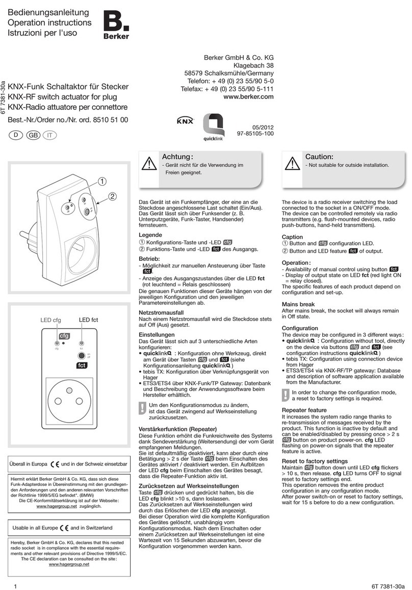
Defines the time base of the delay period.
Time = Base Factor
Delay on return of bus
voltage
Factor (3...127)
3 bis 127, 17 Defines the time factor of the delay period.
Time = Base Factor
Presettíng: 1 s ·17 = 17 s
Debouncing time for binary
inputs
Factor (10...255) * 0.5 ms
0 to 255, 60
Defines the software debouncing time in common
for all binary inputs. A signal edge at the input will
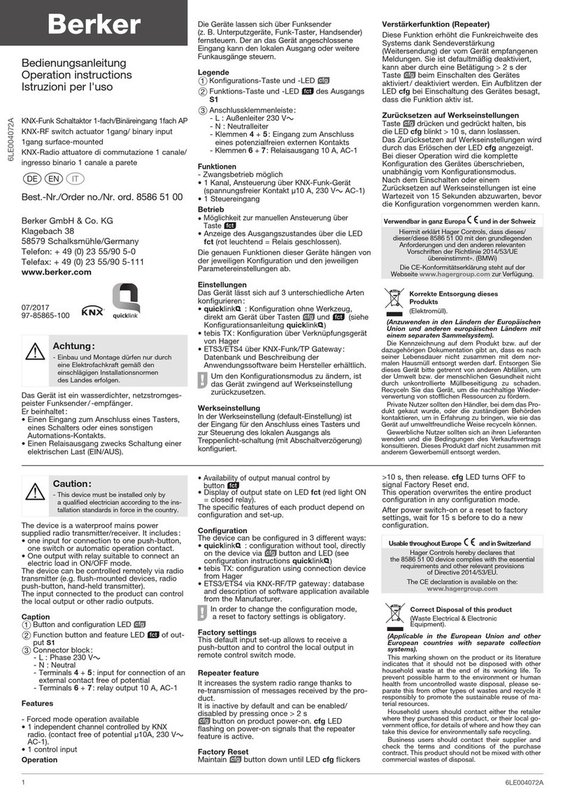
be evaluated with a delay corresponding to the
time defined.
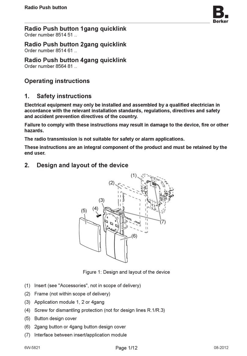
Time = 0.5 ms Factor
Presetting: 0.5 ms 20 = 10 ms
Telegram rate limitation
enabled
disabled The telegram rate limitation can be enabled or
disabled. When the telegram rate limitation is
enabled, no telegrams will be transmitted in the
first 17 s after bus voltage return.
Telegrams per 17 s 30
60
100
127
When the telegram rate limitation is enabled, the
maximum number of telegrams in 17 s can be
preset here.
Shutter/blind actuator 1gang 6A flush-
mounted
75341002
Technical
Documentation
© Berker GmbH & Co KG 2005 Version: 17.08.2005 Part 7
(Subject to prior change) 75341002.doc Seite: 18 / 35
Parameters
Description Values: Comment:
Shutter/blind output, General
Shutter/blind type (HA)
Blind
Shutter
The actuator controls only blinds.
The actuator controls only shutters.
Safety function (HA) disabled
enabled
Enables the safety function.
Sun protection function (HA) disabled
enabled
Enables the sun protection function.
Priorities (HA) Same priority for manual control
and sun protection
Manual control higher than sun
protection
Sun protection higher than
manual control
Defines the priority evaluation for sun protection
and manual control.
manual control
sun protection
sun protection
safety safety
same priority sun protection above
manual control
sun protection
safety
manual control
above sun protection
manual control
manual control
Important:
An incoming safety message always has the
highest priority.
Response after bus voltage
failure
Moving UP
Moving DOWN
Stop
No reaction
Defines the response of the shutter/blind output
on bus voltage failure.
The shutter/blind moves up on bus voltage
failure.
The shutter/blind moves down on bus voltage
failure.
The shutter/blind stops on bus voltage failure.
No reaction.
Response to bus voltage
return
Moving UP
Moving DOWN
Stop
Defines the response of the shutter/blind
actuator on return of bus voltage.
The shutter/blind moves up on bus voltage
return.
The shutter/blind moves down on bus voltage
return.
The shutter/blind stops on bus voltage return.
Shutter/blind actuator 1gang 6A flush-
mounted
75341002
Technical
Documentation
© Berker GmbH & Co KG 2005 Version: 17.08.2005 Part 7
(Subject to prior change) 75341002.doc Seite: 19 / 35
Parameters
Description Values: Comment:
Shutter/blind output, Times
Short operation
Time base
8 ms
130 ms
2.1 s
33 s
Defines the time base for short operation (STEP).
Step-time = Factor •Base
Short operation
Time factor (0…255)
(0 = only stop)
0 to 255, 64 Defines the time factor for short operation
(STEP).
Presetting: 8 ms •64 = 512 ms
Long operation
Time base 8 ms
130 ms
2.1 s
33 s
Defines the time base for long operation (MOVE).
MOVE operation-time = Factor •Base
Long operation
Time factor (0…255)
(0 = infinite)
0 to 255, 30 Defines the time factor for long operation
(MOVE).
Presetting: 2.1 s •30 = 63 s
Blind movement time
Time base
(HA)
8 ms
130 ms
2.1 s
33 s
Defines the time base for the blind moving-time
from upper to lower limit position.
Only if "Shutter/blind type = blind" and sun
protection function enabled.
Blind movement time
Time factor (0…255)
(HA)
0 to 255, 30 Defines the time factor for the blind moving-time
from upper to lower limit position.
Presetting: 2.1 s •30 = 63 s
Only if "Shutter/blind type = blind" and sun
protection function enabled.
Shutter movement time
Time base
(HA)
8 ms
130 ms
2,1 s
33 s
Defines the time base for the shutter moving-time
from upper to lower limit position.
Only if "Shutter/blind type = shutter" and sun
protection function enabled.
Shutter movement time
Time factor (0…255)
(HA)
0 to 255, 30 Defines the time factor for the shutter moving-
time from upper to lower limit position.
Presetting: 2.1 s •30 = 63 s
Only if "Shutter/blind type = shutter" and sun
protection function enabled.
Slat movement time
Time base
(HA)
8 ms
130 ms
2.1 s
33 s
Defines the time base for the slat moving-time
from upper to lower limit position.
Only if "Shutter/blind type = blind" and sun
protection function enabled.
Shutter/blind actuator 1gang 6A flush-
mounted
75341002
Technical
Documentation
© Berker GmbH & Co KG 2005 Version: 17.08.2005 Part 7
(Subject to prior change) 75341002.doc Seite: 20 / 35
Slat movement time
Time factor (0…255)
(HA)
0 to 255, 30
Defines the time factor for the slat moving-time
from upper to lower limit position.
Presetting: 2.1 s •30 = 63 s
Only if "Shutter/blind type = blind" and sun
protection function enabled.
Break during change of
direction
0.5 s
1.0 s
1.5 s
2.0 s
Defines the break during a change of direction
(switch-over delay).
The switch-over delay in the event of a change of
travel direction caused by bus voltage failure is
fixed at 125 ms.
In the unprogrammed state of the shutter/blind
actuator, the switch-over delay is factory-
adjusted to 1 s.
Parameters
Description Values: Comment:
Shutter/blind output, Sun protection (only if "Sun protection function = enabled") (HA)
Sun protection active at
object value (HA)
1 (0 = sun protection
deactivated)
0 (1 = sun protection
deactivated)
Defines the polarity of the sun protection object.
Sun protection position Blind
(0...100 %)
(HA)
0 to 100 %; 50
When the automatic sun protection is active, the
blind position thus preset is approached from the
upper limit position.
Only if "Shutter/blind type = blind".
Sun protection position
Shutter (0...100 %)
(HA)
0 to 100 %; 50
When the automatic sun protection is active, the
shutter position thus preset is approached from
the upper limit position.
Only if "Shutter/blind type = shutter"
Sun protection position
Slat (0...100 %)
(HA)
0 to 100 %; 50
When the automatic sun protection is active, the
slats move to the position thus preset.
Only if "Shutter/blind type = blind".
Response at the end of
automatic sun protection
(HA)
No reaction
Moving UP
Moving DOWN
Stop
Defines the reaction of the shutter/blind output
after deactivation of the sun protection.
No reaction.
The shutter/blind moves up after sun protection.
The shutter/blind moves down after sun
protection.
The shutter/blind stops at the end of sun
protection.

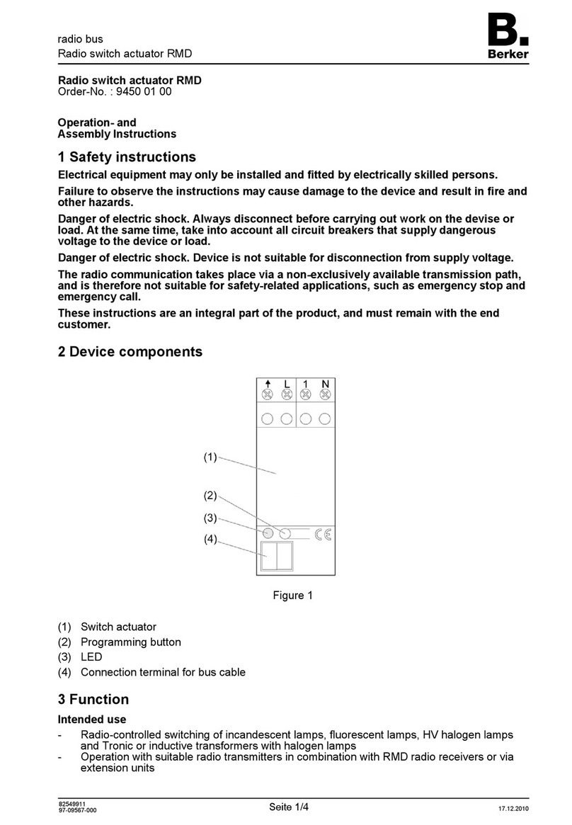
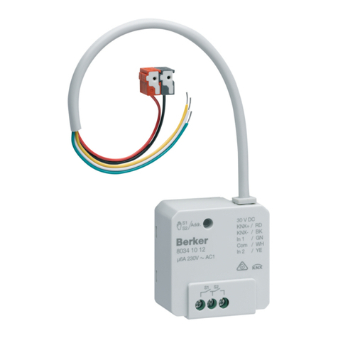
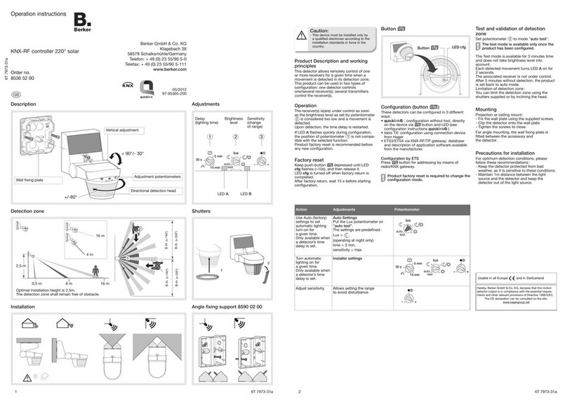
Other Berker Controllers manuals

Berker 8536 52 00 User manual

Berker

Berker 8536 52 00 User manual

Berker 85865100 User manual

Berker

Berker 85865100 User manual

Berker 9450 01 00 Service manual

Berker

Berker 9450 01 00 Service manual

Berker RMD Service manual

Berker

Berker RMD Service manual

Berker 7574 01 01 Product guide

Berker

Berker 7574 01 01 Product guide

Berker 8536 51 00 User manual

Berker

Berker 8536 51 00 User manual

Berker 7531 10 1 Series Product guide

Berker

Berker 7531 10 1 Series Product guide

Berker 8510 51 00 User manual

Berker

Berker 8510 51 00 User manual

Berker 9450 0200 User manual

Berker

Berker 9450 0200 User manual

Berker 7531 40 18 User manual

Berker

Berker 7531 40 18 User manual

Berker KNX-RF 8547 51 00 User manual

Berker

Berker KNX-RF 8547 51 00 User manual

Berker 7531 40 15 User manual

Berker

Berker 7531 40 15 User manual

Berker 8526 51 00 User manual

Berker

Berker 8526 51 00 User manual

Berker 8536 52 00 User manual

Berker

Berker 8536 52 00 User manual

Berker 7531 40 13 User manual

Berker

Berker 7531 40 13 User manual

Berker 8526 51 00 User manual

Berker

Berker 8526 51 00 User manual

Berker 7534 10 11 User manual

Berker

Berker 7534 10 11 User manual

Berker 7531 80 03 User manual

Berker

Berker 7531 80 03 User manual

Berker 85475100 User manual

Berker

Berker 85475100 User manual

Berker KNX-RF User manual

Berker

Berker KNX-RF User manual

Berker Radio Push button 1gang quicklink User manual

Berker

Berker Radio Push button 1gang quicklink User manual

Berker 7534 10 12 User manual

Berker

Berker 7534 10 12 User manual

Berker RMD 75314013 Guide

Berker

Berker RMD 75314013 Guide

Berker 7531 60 03 User manual

Berker

Berker 7531 60 03 User manual

Popular Controllers manuals by other brands

Pivot THC-M user manual

Pivot

Pivot THC-M user manual

Radius A Series Operation and instruction manual

Radius

Radius A Series Operation and instruction manual

IBM ServeRAID M1015 SAS/SATA Quick install guide

IBM

IBM ServeRAID M1015 SAS/SATA Quick install guide

Mitsubishi Electric MELSEC Q Series user manual

Mitsubishi Electric

Mitsubishi Electric MELSEC Q Series user manual

EnOcean PEHA Easyclick Plus Installation and operating instructions

EnOcean

EnOcean PEHA Easyclick Plus Installation and operating instructions

KAESER KOMPRESSOREN SIGMA CONTROL 2 Service manual

KAESER KOMPRESSOREN

KAESER KOMPRESSOREN SIGMA CONTROL 2 Service manual

Missouri Wind and Solar 3PAL-DIG-12V Information and Custom Programming Instructions

Missouri Wind and Solar

Missouri Wind and Solar 3PAL-DIG-12V Information and Custom Programming Instructions

Cairox TSCTK-1 Series Original user manual

Cairox

Cairox TSCTK-1 Series Original user manual

Siemens RWD32 Installation and commissioning guide

Siemens

Siemens RWD32 Installation and commissioning guide

Maxcess Fife Polaris DP-20 user manual

Maxcess

Maxcess Fife Polaris DP-20 user manual

Kkmoon BT14 user manual

Kkmoon

Kkmoon BT14 user manual

Yaesu G-650A user manual

Yaesu

Yaesu G-650A user manual

SIMES S.3491 INSTALLATION, USE AND MANTEINANCE AND WASTE MANAGEMENT INSTRUCTIONS

SIMES

SIMES S.3491 INSTALLATION, USE AND MANTEINANCE AND WASTE MANAGEMENT INSTRUCTIONS

Outwell Trinidad Gas Regulator I instruction manual

Outwell

Outwell Trinidad Gas Regulator I instruction manual

DMP Electronics X1 Installation and programming guide

DMP Electronics

DMP Electronics X1 Installation and programming guide

Danfoss AMI 140 Series datasheet

Danfoss

Danfoss AMI 140 Series datasheet

Kantech KT-1 quick start guide

Kantech

Kantech KT-1 quick start guide

RK Rose+Krieger MultiControl duo accu Assembly instructions

RK Rose+Krieger

RK Rose+Krieger MultiControl duo accu Assembly instructions

manuals.online logo
manuals.online logoBrands
  • About & Mission
  • Contact us
  • Privacy Policy
  • Terms and Conditions

Copyright 2025 Manuals.Online. All Rights Reserved.