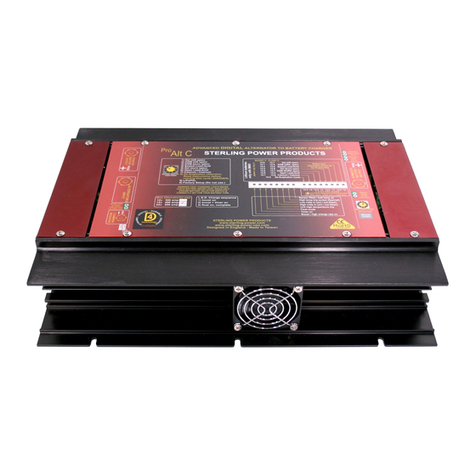
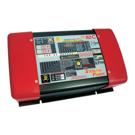
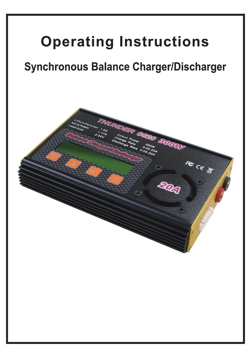
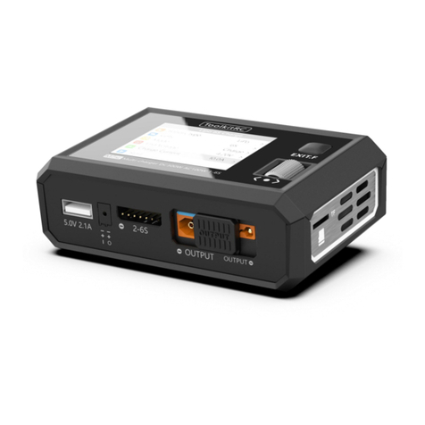
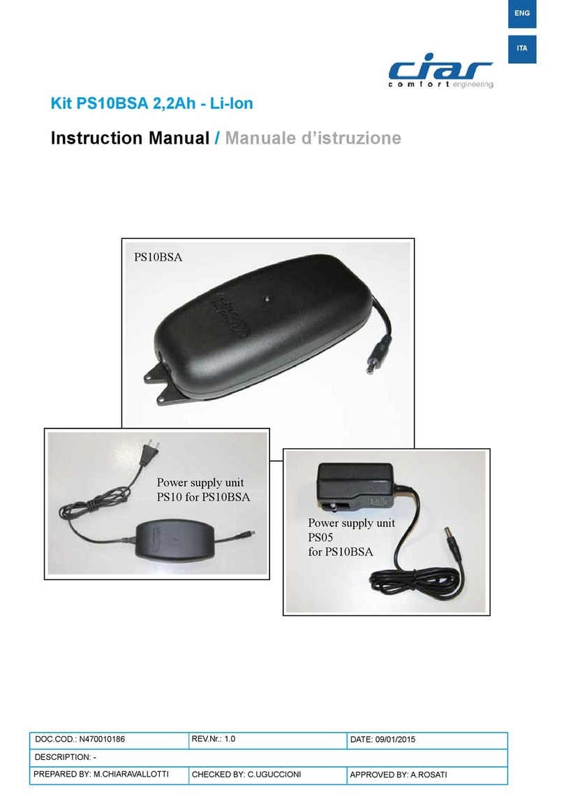
Sterling AB1290 Service manual

STERLING POWER PRODUCTS
ALTERNATOR - to - BATTERY CHARGER
Advanced charging technology
Installations Instructions
& manual
Installations- und
Bedienungsanleitung
AB1290
AB12160
AB2460
AB24120
REMOTE CONTROL (OPTION)
ORDER NO: ABRC
Battery-Battery
Charger
Sterling power products CE
on/off
1
2
3
4
light
alarmalarm
Alarm shutdown
System disengaged
Low input voltage
System o.k.
2
1
3
4
14.4 V timer
40.2 A 134 min
200 amp shunt
ab
200 amp shunt
ab
Pro Digital

Advanced Digital Voltage Amplifier 10 All yellow circles with numbers
on them are referenced to the
installation drawing on page 5
What does it do:
A.G.M./sealed. This has a charger voltage of about 14.1 volts
The clever part:
(see the Sterling universal digital alternator regulator range).
To install the unit:
The solution:
The worry:
Extra wiring to enhance the performance of the unit
Battery temp:
Alternator high temp disengage
Installation:
Program the battery type into the unit: Domestic sense:
NON SEALED LEAD ACID:
GEL / EXIDE SPECIFICATION: Starter solenoid:
This unit is a combined split charge diode system and a voltage amplifier.
The unit comprises of one alternator input and two battery bank outputs. GEL/ U.S.A. SPECK. For some reason the gel is different in the
The output marked starter battery is a straight channel through a diode U.S.A. and they have asked for a lower charge voltage of 14.1 volts at a
which has no boost function as it is the channel that must be connected to different time setting which then drops to float.
the boat/vehicle engine system , most vehicle E.C.U. systems cannot deal
with a high input voltage because this would set off alarms in the E.C.U.
system (engine electronic management system). The assumption we are
making is that the channel marked domestic battery is independent from
the engine starter system and that none of the engine management system
is connected to it (a common negative is alright and essential for the
system to work). The base operation of this system is very straight My advice is to use the open lead acid batteries wherever possible as they
forward: Simply an alternator with a split charger diode system with two are also the lowest cost-avoid gel by far (the worst type of batteries are
outputs. sealed/a.g.m.). Install the unit as close as possible to the alternator and
batteries (taking into account the above requirements). If you need to fit it
First of all, let me explain why in an enclosed engine room (e.g. in a small yacht where the engine room
is fully enclosed with sound proofing - where I come from this is called an
oven :-), then try to install any equipment as low as possible, ideally
wever, this is not always easy to fit, and with some modern vehicle outside the engine room near to the battery box. (On a separate note:
engine management systems and warrantees it may also not be possible to Always remember that the only air-cooled item in the engine room is your
fit. There are two ways to get the maximum out of an alternator: Either alternator which means that if you have a totally sealed room you should
increase the voltage coming out of the alternator (fit an advanced not be surprised if you go through alternators on a regular basis. If the
alternator regulator) or pull the alternator’s voltage down so that the engine room is sealed, then put a vent tube from outside to the back of the
alternator’s own regulator works at full performance. Both of the above alternator. This will enable the alternator to suck air through the back to
options work as far as maximising the alternator output is concerned. cool itself and you will not experience any alternator problems.)
However, with the second option (pulling the alternator voltage down)
you would find that even though you have maximised the alternator’s 1) Connect the main alternator output (B+) to the centre stud marked
performance as intended, you have also ended up with a voltage and alternator input and then simply connect the other two studs, one to the
current which are absolutely useless for battery charging purposes. A engine battery and one to the domestic battery. Please ensure that the
standard alternator is set at about 14 volts. So if we pull the voltage down cable used can carry the full current of the alternator. It is always best to
to 13 volts to maximise the alternator’s current, then 13 volts is no good have 2 x plus the capability to reduce voltage drops, i.e. if you have a 70
for charging batteries fast. (Calm down, you haven’t wasted your money amp alternator, then use a 140 amp cable.
on this thing :-) 2) The unit has a smaller negative wire which requires a 60 amp cable and
If you pulled the voltage down and ended up with a useless should be connected directly to the alternator negative at the alternator
voltage as described above, but thereafter amplified the voltage from 13 to case or negative stud. This wire is a lot smaller than the alternator cable
14 .8 volts and fitted a 4-step digital control system (as used by our which may sound confusing as you would think that if you had a 100 amp
battery chargers and advanced regulators), then you would have the alternator with a 200 amp cable on the positive, then you would require a
benefits of pulling the alternator down as well as the benefits of the 200 amp cable on the negative (don’t ask as it would take a book to
advanced regulator - all in one box. explain, but just trust me that the smaller cable is alright).
The only concern with the above-detailed system is that it 3) If you already have a split charger diode, then the three positive cables
may have negative effects on the engine start battery which at the end of are already there. Simply replace the diode with this unit and connect the
the day is the most important battery. We have therefore incorporated two negative.
software functions into our design which will ensure that the battery For the basic installation ‘that’s it’, ‘job done’. Simply switch on the
remains fully charged. The amplifier is not used for the first 2.5 minutes engine and the software will fire up the unit, ‘and away it goes’.
(the top green light will flash to show that the system is working) and
even though the software is in control, it is not doing anything in order to In order to improve the performance of this unit we have added extra
ensure that a maximum amount of amps are fed into the starter battery features which all help, but are not required for the unit to work.
which in turn allows the battery to recover in the fastest time possible. The Simply connect one of the enclosed temperature
amplified section is then switched off every 15 minutes (for another 2.5 sensors to a battery terminal post (negative or positive) and to the two
minutes) to ensure that the engine start battery is alright. The unit small terminals marked battery temp and the system will pick up the heat
(when on maximum amplification) has the ability to pull the alternator through the lead. The output voltage will be reduced in accordance with
down to 10 volts which would result in the loss of the engine start system. the manufacturers’ battery charging temperature curves and in the event of
Similarly, if you were to put a heavy load on the engine system (such as the battery temperature increasing due to battery failure and the
putting on the headlights of a vehicle), then you would lose the engine temperature reaching in excess of 50 deg c (major problem), the unit will
battery which obviously is not acceptable. In order to overcome this switch off the amplifier. (However, the straight through path from the
problem, we have therefore added a low volts regulator on the vehicle alternator is still connected which means that if the problem which has
battery so that it will never go below 13 volts. Even when the alternator is caused the batteries to overheat is the failure of your standard
completely exhausted, the engine system will always have power priority, regulator in the alternator, we will give a warning, but won’t be able
despite the fact that the other side is much more powerful. As you can see to stop it).
from the graphs of an actual test run, the vehicle’s battery continues to
charge even when the boost is working at full power. :This is another temp sensor
(supplied) that should be connected to your alternator output post (B+)
The installation process is very easy. If you already have a split diode, and which will disengage the amplifier in the event of the alternator
then it’s simple; if not, just follow the instructions. Install the unit in a reaching 100 deg c. This will not set off an audible alarm, but simply
cool, dry and well-ventilated position as it is not waterproof, and please indicate the problem with a l.e.d. The remote (if fitted) will then show
make sure not to fit it in a box as the heat produced by the unit must be when the alternator has cooled down enough for the system to
got rid of. automatically re-engage and carry on its work.
Go to the battery type, The unit comes as standard with the facility to sense
program the dip switches on the unit and set the battery type. There are all the control voltages at the unit. However, if you would like to sense the
three main types of battery: voltage at the domestic battery directly in order to overcome the voltage
(or sealed lead acid where you can drops in the cable run drops, then simply connect a cable from the
unscrew the lid of the battery and top it up with water): This type of domestic sense connection directly to the domestic battery
battery has a long life and is the best for fast charging (max voltage 14.8).
Some alternators cannot work if there is no voltage
Always remember that fast charging costs water, so if the battery is
sealed and you cannot top up the water then do not use it for fast
charging. Open lead acid batteries are best for domestic systems.
the most effective way to get the most
out of your alternator system is to use an ‘Advanced’ alternator
regulator
see the basic installation drawing
down by Exide for its gel batteries. Basically it is 14.4. volts for about
10-14 hourss, regardless of the state of the batteries, then it drops to
float
with a
software timed cycle which then drops to float at about 13.5 volts.
Most so-called a.g.m. batteries are in fact only sealed lead acid.
Ho
This is the new specification laid
6
1
10
3
4
Sterling power products CE
on/off
light
alarmalarm
System trip
System Disengaged
temp
4a+b
set up
3a+b
Low voltage warning
System within limits
Screen
Main
1
Eng
2
Dom 12.3v 50A
Alt 12.8v 50A
Start 12.7 4A
Timer: 134 m
Alt Temp + 20C
Bat Temp + 20C
Case LHS + 17C
Case RHS + 23C
Alt Controller
Power 13% Bost
System set:12v
Bat Type : Wet
Dom 12.3v 50A
Alt 12.8v 50A
Screen1:
Screen2:
Screen 3a:
Screen 3b:
Screen 4a:
Screen 4b:
Push button marked Main 1. This is the main screen and the one it is best to leave the unit on.
It shows the domestic battery voltage and current as well as the alternator output current and
voltage
Push button marked Eng 2. This shows the engine battery voltage and current. It also shows
the time calculation for the high charge rate and the count down to the float charge.
Push button marked Setup 3 a+b: There are two screens on this button. Push once for screen
‘a’, then once again for screen ‘b’. Screen ‘a’ shows the system setup, e.g the system is a 12 v
system and the battery type selector is for wet (conventional lead acid). This refers to the
domestic battery only.
Push button marked Setup 3a+b: There are two screens on this button. Screen ‘b’ shows the
effective boost being delivered at this time and ranges from 0% (during the rest periods and on
float) to 100% when system on full power.
Push button marked Temp 4a+b: There are 2 x screens on this button. Push once for screen a,
then again for screen b. Screen a shows the alternator temp and the domestic battery temp, if
the temperature sensors are not fitted it will default to 20 deg c
Push button marked Temp 4a+b: There are two screens on this button. Push once for screen
‘a’, then again for screen ‘b’. Screen ‘b’ shows the box heat sink temperatures. LHS stands for
left hand side. Guess what RHS stands for :-)
Do not expect these to be the same temperature.
on/off: This switches off the unit boost
aspect, but cannot prevent the standard
diode splitting from working. The
monitoring functions remain on, and the
only way to know if the unit is switched off
is by checking that the system within limits
(l.e.d.) is off and that the boost off is on
screen 3b.
Alarm: This mutes the alarm system.
Back ground light: This switches the
background light on and off.
Optional Extra Remote control kit includes parts: see page 4
Remote Panel
200 amp shunt
200 amp shunt
pre made cable
pre made cable
Advanced Digital Split Charge
Alternator Voltage Amplifier
11
12
5
8
9
on their main B+ terminal which fires up the alternator. This is easy to see
because when you fit a spit charge diode there is no feed on the B+ which
in turn means that the engine will start, but that the alternator may not
work. If this is the case, the way to overcome this is to use the starter
solenoid feed. This is a simple feed that connects the terminal on the
starter motor and which only becomes live when the starter motor bendix
is engaged (i.e. the first two seconds of having the ignition key fully on). As soon as the unit is connected it senses the output voltage from the
Then when the starter is disengaged, the point becomes dead. What alternator, so when the alternator starts up, there will be a slow flashing of
actually happens is that a 12 volt feed is sent to the alternator B+ terminal the top green l.e.d. This confirms that the unit is working (even though it
for the starter duration (which is enough) and that then fires up the remains inactive for the first 2.5 minutes to allow a little time for the
alternator. After this the alternator then looks after itself. engine battery to recover). After this time period the green light will
discontinue flashing and display a continuous green instead. The chances
An optional extra with this unit is are that the engine load will increase. The system is then on constant
the remote control kit which comes complete with a remote display and current and the unit should be boosting the current into the domestic
two 200 amp shunts plus two 150 amp cable link wires.
battery bank. This high current will continue for about 15 minutes after
The two shunts measure both the domestic and the engine battery which it will stop for 2.5 minutes in order to ensure that the engine battery
current, and the software works out the alternator current. The remote is alright. Once the domestic battery reaches 13.9 volts, the trimer l.e.d.
measures things such as voltages and temperatures, and in the event of a will come on and the high charge rate will continue for the time from
problem it does not only display what the problem is, but also what needs switch on to 13.9 volts x 10, with a minimum of one hour and a maximum
to be done about it. of six hours. The rest periods every 15 minutes for 2.5 minutes are also
taken into account during this period
If on start-up nothing happens, then:
The remote kit comes with the two shunts, plus two heavy connector 1) Test the alternator voltage. It should be about 13.8 volts, but if it isn’t
cables . It is very important that the small sensor cables you need to fit are then the unit is at fault.
connected the right way round as otherwise the current readings will not 2) If the alternator voltage is below 10 volts, then the alternator is either
be correct. Look at the p.c.b drawing. with the and markings and defective, or it may not be working because it needs 12 volts on the B+
connect the sensor cables to the shunt in the correct position as per the terminal for it to work successfully. To check if this is the case, simply
drawing on the full installation drawing, use low current 3-5 amp cable short out between the alternator connection and one of the battery
connections in order to set 12 volts up the alternator cable. If the alternator
Internal adjustments (not required as fires up and everything works, then look at the extra terminal marked Ing
standard). feed, and connect this to the starter motor solenoid engagement as per the
instructions. This will shoot 12 volts up the line to fire up the alternator.
3) The unit needs about 12.6 volts on the alternator to work as failure to
reach this voltage will prevent the amplifier from coming on line.
However, the basic split charge diode should still be operating.
4) If there are 14 volts going into the unit and only 12.6 or less coming
out, then the diodes have failed and the unit needs to be repaired.
Start-up and test procedure:
Remote control kit:
Install shunts: for remote panel ( optional extra )
Shunt type adjustments:
switching on the switch number 1 on the regulation voltage, the engine
battery is dropped from 13 to 12.8 volts which in turn improves the boost
effect from the unit.
This unit comes set up for the standard Sterling 200 amp shunt
(1 mv = 1 amp), however, it can be re-programmed to accept a 500 amp
shunt (0.1 mv = 1 amp). Make sure that you do not make adjustments
unless you fully understand how to. If in doubt, please call us for help.
Most regulators come as standard between about 13.8 and 14.4 volts. If
the standard regulator is not within its limits and has a low voltage
performance of below 13.8, the unit may not work as well as it could. By
Warning: Do not do this unless you have the above-
described problem as this could result in a low engine start battery
performance.
Low alternator regulator adjustment: (standard set switch 1 off)
8
5911 12
89
1515151515
ab
ON
13
ON
14

What do I expect to see from this unit and why?
The current graph
System voltage graph
Position : The interesting point here is that this is the magic point, the point where
The below test was set up and monitored and is as close as possible as to what happens the domestic battery voltage exceeds the alternator input voltage. This is what the
on the average split charger system, the engine battery is a 100 amp hr standard lead process is all about.
acid, and the domestic battery is 3 x 100 amp hr standard lead acid. The engine battery The steps on the graphs show the unit boosting every 15 minutes, then resting for 2.5
was discharger to 11 volts ( about 10 engine starts ) and the domestic bank to about 11 minutes. An example of this is the time period between and .What you can see
volts ( will no longer run an inverter and is about 60% empty . The alternator used is a here is that by switching off the amplifier (to help the engine battery charger more),
Bosch 90 amp with a standard 13.9 volt ( variable ) regulator. the unit battery type is the engine battery voltage curve increases during that step shown at point which
programmed to open lead acid. results in extra current going into the engine battery at position . The current
There are 2 x graphs , one is the current into the batteries, and the other is various reflection of this process is reflected in the other graph marked ‘the current graph’.
voltages on the system shows the current flow into the engine start battery and the domestic
: system. The effect of the amplifier can be clearly seen when the unit switches off for its
The key points to pick up on here are: 2.5 minutes rest cycle. The current drops from position = 95 amps to position =
The yellow trace (alternator voltage into the unit) clearly shows that the system is about 30 amps, a 300% difference. At the same time you can see extra going into the
doing its job. It is designed to pull this voltage down a little to enable the standard starter battery which clearly charges through the whole exercise.
alternator regulator to produce its full current. You can clearly see that on position on On completion the unit switches off, and the process continues as a conventional split
the voltage curve the voltage is pulled down to position . The result in current change charger system , if however the domestic battery falls below 12 volts, the system
is from position - which is about 70 amps improvement and a good will auto restart and continue the process again.
increase in current. Shows that the engine battery is full and taking no more current.
CONSTANT CURRENT
slow flash unit in-active
TIMER ACTIVATED
FLOAT/CONSTANT V
LOW BATTERY VOLTS
HIGH BATTERY TRIP/V
BATTERY TYPE
HIGH ALT VOLTAGE TRIP
HIGH ALT TEMP DISENG
HEAT SINK R.H.SIDE
HEAT SINK L.H.SIDE
Green High Charge Rate On: (top L.E.D. 1) This should be on from start-up (slow flash shows unit is on, but on rest mode, for
the first 2.5 mins on start-up and every 20 minutes or so thereafter, see graph ) and shows that the alternator should be
working at its maximum. It should remain on until the green float comes on and this shows that the high charge rate is
complete.
Yellow Timer Activated: This comes on when the voltage reaches about 13.9 - 14 volts (x 2 for 24 v), and depending on how
long it took to come on, will dictate how long the timing cycle will remain on. The software will calculate the timing for the
high charge rate. This will vary from 1 - 6 hours and the time will be displayed on the remote panel and a count down . This
light will remain on until the high charge rate is over, and will go out at the same time as the high charge rate between 1-6
hrs after activation.
Green Float Mode: This indicates that all the high charge cycles are now over and should remain on after all the high charge
lights are out. The system is now running at a standard charge rate only (about 14 volts) regulated on the battery.
Orange Low Voltage Warning: This is simply says that there is a low voltage at the main battery bank and has no active
function. For information only; usually indicates a defective alternator.
Red Dual Information L.E.D: This L.E.D. Has two functions and as such has two display modes. flashing = high temp trip and
l.e.d. on permanent = high battery voltage trip
Tri Coloured L.E.D: This simply displays the battery type that the processor has been set to. This is a tri-coloured l.e.d.
Yellow = open lead acid, Green = gel /sealed lead acid . Red = A.G.M..
Red High Alternator voltage trip: This will warn you and switch off the boost section. This means that your alternator’s own
regulator has failed and that the alternator will now boil and destroy your batteries. There is simply nothing we can do about
this, except warn you. and stop your engine as soon as possible. Remove the
alternator input cable, then continue your journey and have the alternator repaired.
Yellow: System disengaged, this refers to the boost section being deactivated for the following reasons: The alternator
temperature sensor has exceeded 90 deg c and has automatically disengaged the unit to allow the alternator to cool down,
there is a high temp on the heat sink, or there is a high temperature on the battery temp sensor. It will reset once the safety
parameter that caused the problem has been reduced.
Red : This gives a simple warning that the product is overheating. In this case the boost section will switch off and should
reduce the problem. However, we cannot prevent the unit continuing to overheat if it has been placed in a bad place such as
a sealed box with no ventilation. If this high temperature is not addressed by increasing the cooling effect , ie by moving the
unit to a cooler place, then it could result in the failure of the unit.
Red: same as above:
Please take this warning very seriously
2
1
4
6
7
3
12.50
13.00
13.50
14.00
14.50
15.00
9
18
28
37
46
55
64
73
83
92
101
110
119
128
138
147
156
165
174
183
193
202
211
220
229
238
248
257
266
275
284
293
303
312
321
330
339
348
358
367
376
385
394
403
413
422
431
440
449
458
468
477
486
495
504
513
523
532
541
550
559
568
578
587
596
TIME min.
Volts
alternator input voltage
starter battery voltage
domestic battery voltage
0.000
0.010
0.020
0.030
0.040
0.050
0.060
0.070
0.080
0.090
0.100
1
16
31
46
61
76
91
106
121
136
151
166
181
196
211
226
241
256
271
286
301
316
331
346
361
376
391
406
421
436
451
466
481
496
511
526
541
556
571
586
Time min.
Amps
100
90
80
70
60
50
40
30
20
10
0
time in mins
time in mins
volts
amps
domestic battery current
starter battery bank current
Domestic battery bank current curve, with engine battery bank current curve
Engine battery bank, domestic battery bank, and alternator voltage curves
4
5
8
9
5
8 9
23
1
6
7
10
10
L.E.D. information and alarms
Unit expectations
10
11
11
1
2
3
4
5
6
7
8
9
10
fan
fan
engine
alternator
ENSURE ALL NEGS ARE COMMON
DOMESTIC BATTERY SYSTEM
200 amp shunt
Engine
battery current
( optional remote kit )
Battery
temperature
sensor
cable
( supplied )
Remote control
and information panel
( optional remote kit )
Starter motor
solonoid
40 amp fuse
+
+
+
Full System wiring
(including optional remote kit if used )Kit parts in green
Engine
starter
key
ENGINE STARTER
BATTERY
lightlight
CE
on/offon/off
beepbeep
1
2
3
4
22
44
33
11
Power Management
with
AMP Hr Counter
Sterling power products
Amp
hr
Amps Volts
14.35 v m Pos 4
37amps 435 a/hrs
Sterling power products CE
on/off
alarm
light
temp
System
Default
Low voltage warning
System Disengaged
System Trip
System Within Limits
Screen
Help
Bat 14.4v Timer
Alt 15.4v 134m
set up
volts
temp sensor
temp sensor
fuse
1
23
4
5
7
Alternator
temperature
sensor
cable
( supplied )
8
11
Advanced Digital Split Charge
Alternator Power Amplifier
Right Hand Side
Left Hand Side
10
14
1 2 3 4
This unit comes set up for the standard
200 amp shunt ( 1 mv = 1 amp ).
however it can be re-programed to
accept a 500 amp shunt 0.1 mv = 1
amp
13
aa
ba
b
b
ON
1 2
ON
1 2
Low alternator regulator voltage
adjustment, this should only be used
if the alternators standard voltage
regulator is set below 13.9 volts . Do
not use unless this is the case. switch,
switch 1 on, switch 2 is not in use
6
OPEN
LEAD ACID
GEL-
BATTERIES
(EXIDE SPECIFICATION)
SEALED LEAD
ACID & AGM
GEL & AGM
(USA SPECIFICATION)
ON
1 2
ON
1 2
ON
1 2
ON
1 2
LED
COLOUR
MAX. CHARGING
VOLTAGE
ABSORBTION
TIME
FLOATING
VOLTAGE
YELLOW
GREEN
GREEN-YELLOW
GREEN FLASHING
FOR 5 SEC.
14.8V / 20°C
14.4V / 20°C
14.4V / 20°C
14.1V / 20°C
13.65V / 20°C
13.8V / 20°C
13.65V / 20°C
13.5V / 20°C
1 - 3 HRS.
10 - 12 HRS.
4 - 8 HRS.
4 - 10 HRS.
ON
15
12
17
16
200 amp shunt
Domestic
battery current
( optional remote kit )
ab9

fan
fan
engine
alternator
ENSURE ALL NEGS ARE COMMON
DOMESTIC BATTERY SYSTEM
40 amp fuse
+
+
Basic wiring System wiring
ENGINE STARTER
BATTERY
fuse
7
Right Hand Side
Left Hand Side
1 2 3 4
ON
1 2
ON
1 2
6
OPEN
LEAD ACID
GEL-
BATTERIES
(EXIDE SPECIFICATION)
SEALED LEAD
ACID & AGM
GEL & AGM
(USA SPECIFICATION)
ON
1 2
ON
1 2
ON
1 2
ON
1 2
LED
COLOUR
MAX. CHARGING
VOLTAGE
ABSORBTION
TIME
FLOATING
VOLTAGE
YELLOW
GREEN
GREEN-YELLOW
GREEN FLASHING
FOR 5 SEC.
14.8V / 20°C
14.4V / 20°C
14.4V / 20°C
14.1V / 20°C
13.65V / 20°C
13.8V / 20°C
13.65V / 20°C
13.5V / 20°C
1 - 3 HRS.
10 - 12 HRS.
4 - 8 HRS.
4 - 10 HRS.
ON
WHAT CABLE TO USE IN mm sq
A charger or inverter up to cable run distance 0-1.5 mtr 1.5 - 4 mtr
0-25 amps 6 mm sq 10 mm sq
25-45 amps 16 mm sq 25 mm sq
45-85 amps 25 mm sq 35 mm sq
85-125 amps 35 mm sq 50 mm sq
125- 180 amps 50 mm sq 70 mm sq
180-330 amps 70 mm sq 90 mm sq
Please note that if there is a problem obtaining for example 90 mm sq cable,
simply
Use 2 x 50 mm sq , or 3 x 35 mm sq , the cable is simply copper, and all you
require
Is the copper , it does not matter if it is one cable or 10 cables as long as the
square

fan
fan
engine
alternator
ENSURE ALL NEGS ARE COMMON
DOMESTIC BATTERY SYSTEM
40 amp fuse
+
+
Basic wiring System wiring
ENGINE STARTER
BATTERY
fuse
7
Right Hand Side
Left Hand Side
1 2 3 4
ON
1 2
ON
1 2
6
OPEN
LEAD ACID
GEL-
BATTERIES
(EXIDE SPECIFICATION)
SEALED LEAD
ACID & AGM
GEL & AGM
(USA SPECIFICATION)
ON
1 2
ON
1 2
ON
1 2
ON
1 2
LED
COLOUR
MAX. CHARGING
VOLTAGE
ABSORBTION
TIME
FLOATING
VOLTAGE
YELLOW
GREEN
GREEN-YELLOW
GREEN FLASHING
FOR 5 SEC.
14.8V / 20°C
14.4V / 20°C
14.4V / 20°C
14.1V / 20°C
13.65V / 20°C
13.8V / 20°C
13.65V / 20°C
13.5V / 20°C
1 - 3 HRS.
10 - 12 HRS.
4 - 8 HRS.
4 - 10 HRS.
ON
WHAT CABLE TO USE IN mm sq
A charger or inverter up to cable run distance 0-1.5 mtr 1.5 - 4 mtr
0-25 amps 6 mm sq 10 mm sq
25-45 amps 16 mm sq 25 mm sq
45-85 amps 25 mm sq 35 mm sq
85-125 amps 35 mm sq 50 mm sq
125- 180 amps 50 mm sq 70 mm sq
180-330 amps 70 mm sq 90 mm sq
Please note that if there is a problem obtaining for example 90 mm sq cable,
simply
Use 2 x 50 mm sq , or 3 x 35 mm sq , the cable is simply copper, and all you
require
Is the copper , it does not matter if it is one cable or 10 cables as long as the
square
Other manuals for AB1290
1
This manual suits for next models
3
Other Sterling Batteries Charger manuals
