Sterling AB1280 User manual
AB1280
AB12130
ABNRC
technology
4
U
R
D
A
B
:
L
L
E
A
T
:
I
D
G
E
I
D
S
I
:
G
C
N
I
M
A
N
Y
D
ProDigital
RoHS
compliant www.sterling-power.com
www.sterling-power.usa.com
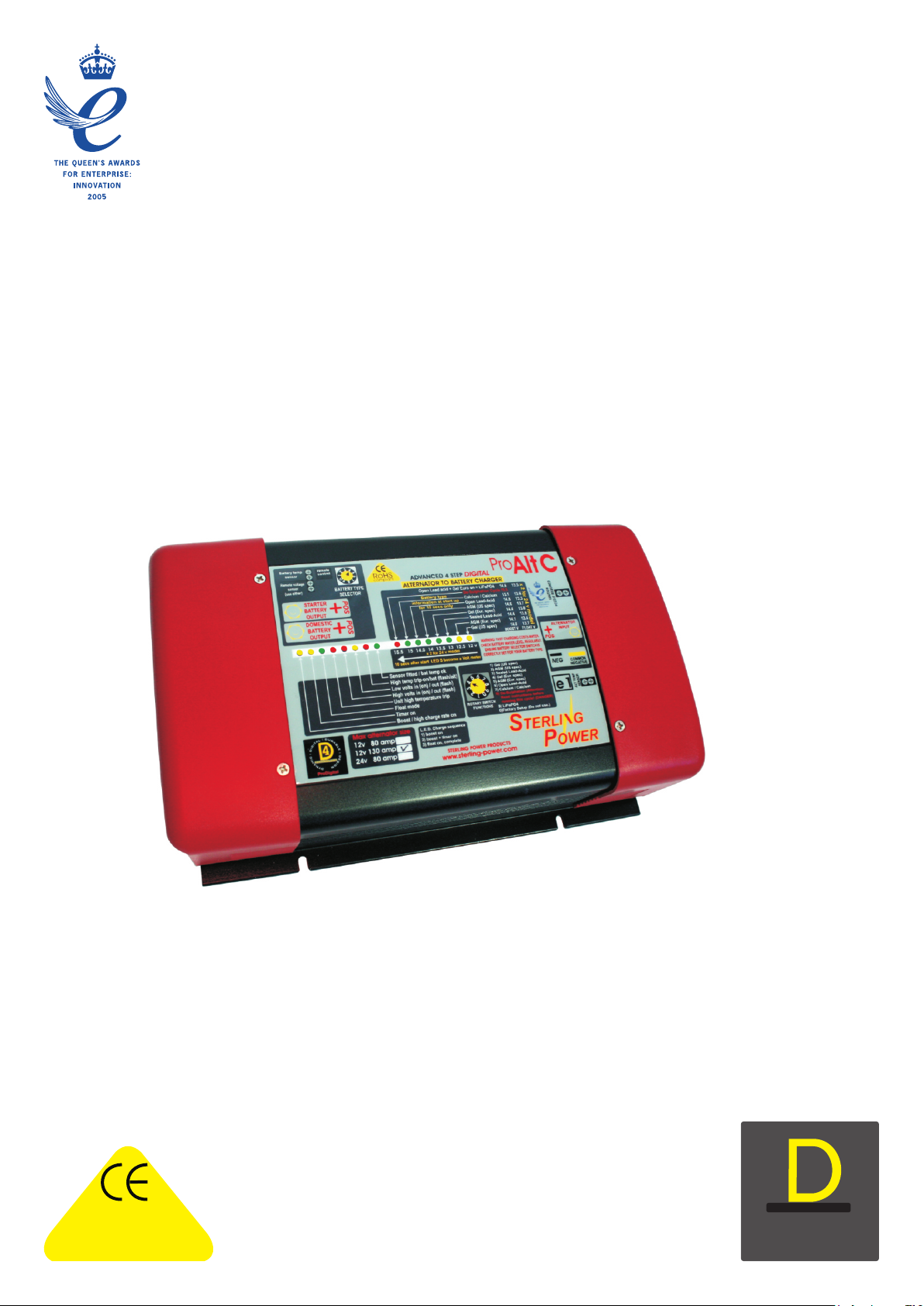
Alternator-to-Battery Chargers
and Remote Control
STERLING
POWER PRODUCTS
e1
12 v 80 - 130 amp
24 v 60 amp

Safety Instructions
General Precautions
Precautions against Gas Explosions
Precautions when Handling Batteries
Do not use on the
positive battery terminal for this connection!
Product Characteristics
Easy installation: It could not be easier. For the basic system only 4 connections are
Before connecting and running your Sterling alternator-to-battery required: one from the alternator(s), one to each battery bank and one to the common
charger, read the complete instructions and all cautionary labels negative. Apart from the additional negative connection most of these cables will be
on the unit and on the batteries. Only a correct installation on board anyway.
according to these instructions will let you take full advantage of
your alternator-to-battery charger. Advanced charging technology: Intelligent, software-controlled, 4step charging of
the domestic battery including temperature compensation.
Always install the unit in a dry, cool and well-ventilated No interference with engine electronics: Because the system does not increase the
place. Any contact with water and heavy humidity has to be avoided. Do not voltage of the starter battery there is no risk of problems with the electronic engine
cover the fans to prevent the unit from overheating. Make sure all cables management system.
have the appropriate size and are in good condition. Do not run the unit with
cables that are damaged or otherwise inappropriate. No work on the alternator required: Absolutely no changes to the alternator are
required. As a result no warranty conflicts can arise.
The alternator-to-battery charger contains Suitable for multiple alternators: Unlike other systems the alternator-to-battery
electrical components which may produce sparks in event of failure. In order charger can be used simultaneously on more than one alternator, saving even more
to avoid the risk of fire or explosion, do not install the unit in rooms installation work and money.
containing batteries or highly inflammable materials or in any place requiring
explosion-proof equipment. This includes any room with petrol, gas or diesel Starter battery priority: The system ensures that the starter battery is always kept in
driven engines or with tanks or piping used for any such substance. Before operational condition.
starting to install the charger please ensure that there is sufficient ventilation. Intelligent fault protection: The unit comprises multiple safety features and fault
In order to prevent the formation of explosive gases make sure that the indicators. Even in the unlikely event of a complete failure, the unit will still work as
batteries have not been charged for at least 4 hours prior to installation. a split charge diode.
Someone should be within earshot, i.e. Enhanced installation options: The unit comes with temperature sensors for the
close enough to come to your aid when working near a lead-acid battery. battery and the alternator. It can be enhanced by an optional remote control.
Have plenty of water and soap nearby in case battery acid comes in contact
with skin, clothes or eyes. Wear complete eye protection and protective
clothing. Avoid touching the eyes while working with a battery. Basic Installation
If battery acid contacts skin or clothing, wash immediately with soap and
water. If acid enters the eye(s), flood eye(s) with running cold water for at
least 10 minutes and seek medical attention immediately.
Never smoke or allow a spark or flame in the vicinity of a battery or the
engine.
Install the unit in a cool and well-ventilated position close to the alternator(s). Also,
Work with extra caution to reduce the risk of dropping a metal tool onto a the installation point has to be dry and free from heavy condensation since the unit is
battery. It may create sparks or short-circuit the battery or other electrical not waterproof. Do not fit it in a closed box as this might lead to overheating of the
parts that may cause an explosion. unit and reduced performance.
Remove all personal metal items such as rings, bracelets, necklaces, watches The unit has three temperature-controlled fans. Therefore they will run more often
and jewlery when working near a battery. A battery can produce a short-circuit when the unit is installed in a place with a high ambient temperature.
current high enough to weld a ring or any other metal which will lead to
Before connecting the unit to your alternator(s) make sure that your alternator-to-
serious burns.
battery charger is rated for the maximum ( combined ) output of the alternator(s).
Never charge a frozen battery.
Connect the main alternator/ s output(s) (B+) to the center stud marked
“ALTERNATOR INPUT. Then simply connect the other studs to the engine battery
General Overview and to the domestic battery, respectively. Make sure that the cables used can carry
The Sterling alternator-to-battery charger is a fully automatic, electronic the full current of the alternator(s). Choose a cable size that can carry at least twice
multi-stage split-charge system which charges two banks of batteries from one as much current than required. For example, if you have a 70A alternator, then use a
or more alternators. It combines an advanced split charge diode system with a 140A cable to reduce voltage drop in the cable and improve performance
powerful voltage amplifier. The unit has one input to connect to one or more If you are only going to charge one bank of batteries, then use the “DOMESTIC
alternators and two outputs to charge two different battery banks. BATTERY” output only. The “START BATTERY” output can remain unused
The output marked “starter battery” is a straight channel through a diode; this without affecting the performance of the unit.You can split the boosted domestic
is the channel that is connected to the boat / vehicle engine system. In order to battery side by using a Sterling Pro Split R 0 volt spliting system or the Current
avoid any conflicts with an electronic engine management system, there is no limiting VSR.
boost function on this channel. The unit has a short negative wire which has to be extended and connected directly
The output marked “domestic battery” comprises an intelligent, software- to the alternator negative (or case) or the common battery neg using a 60A cable.
controlled boost function which charges the domestic battery bank up to five If you currently have a split charge diode, then the three positive wires are already
times faster and much more efficient than a standard alternator could do. In there. Simply replace the split charge diode with the alternator-to-battery charger and
addition, the batteries will take in up to 50% more charge current, allowing connect the negative wire to the alternator neg or the nearest main comm neg.
you to utilize their full capacity. Important: If your alternator has got its own battery voltage sense wire, then this has
While the alternator-to-battery charger greatly improves the charging of the to be removed from the battery terminal and should be connected to the alternator’s
domestic battery bank, the starter battery has always priority, ensuring that the own B+ output instead. This will prevent contradictory regulation between the
engine can be started at any time. Under no circumstances will the system alternator and the alternator-to-battery charger.
allow the starter battery to drop below 13V. Extended Installation
Additional functions protect your electrical system and your batteries from For additional functions and improved performance some extra features can be
possible faults such as overcharging or over temperature caused by the installed. Note that this extended installation is optional and is not required for the
alternator to battery charger. Any fault on the system will be indicated by a unit to work.
number of LEDs or on the optional remote control unit.
Battery Temperature: Using its ring terminal end, connect one of the enclosed
temperature sensors to your domestic battery’s negative post.
In order to maximist the alternator output current, the alternator-to-battery Connect the two small wires on the
charger pulls the alternator output voltage down to about 13,3V. Then this low other end to the small terminals marked “battery temp”. Be careful not to damage or
voltage is amplified to a higher voltage suitable for effective battery charging, alter the temperature sensor in any way! The system will then sense the battery
i.e. 14.1V to 14.8V. The unit’s intelligent software automatically calculates the temperature and change the output voltage in accordance with the recommended
optimum charge cycle and absorption time. When the batteries have been temperature compensation for the selected battery type.
fully charged, the voltage is reduced to float voltage (appr. 13.5V to 13.8V) if
possible, depending on the output voltage of the alternator.
Important: All voltages indicated in these instructions refer to an ambient
temperature of 20°C. When using a battery temperature sensor these voltages will be
How it works
The temp sensor does not
need to be used for the unit to work,
Important: These guidelines refer to the connections
that have to be made for the correct installation of the Sterling Alternator-to-Battery
Charger. On an existing system you may also be required to remove some of the
original connections that were used to charge the batteries prior to the installation of
the unit.
ALTERNATOR-TO-BATTERY CHARGER
INSTRUCTIONS

different due to temperature compensation.
Alternator Temperature: Using its ring terminal end, connect one of the
enclosed temperature sensors to your alternator case or negative stud.
Connect the two small wires on
the other end to the small terminals marked “alt temp”. Be careful not to damage
or alter the temperature sensor in any way! The system will then sense the
alternator temperature and will disengage the voltage amplifier if the alternator
temperature exceeds 100°C.
Voltage Sensing: The alternator-to-battery charger in its standard
configuration senses all voltages directly at the unit. However, in order to
compensate a possible voltage drop between the unit and your domestic battery,
you can run a simple 0.5mm² wire from the positive stud of your domestic battery
to the terminal marked “dom sense”.
Starter solenoid: Some alternators will not fire up without a voltage on their
B+ terminal. Because the alternator-to-battery charger contains a split charge
diode there will be no voltage feed on the B+ terminal which means that the
engine will start but the alternator may not work. If this is the case, then simply
connect a ignition feed ( from the key switch ) which becomes live when the
engine is started. this will feed 12 v through the unit and fire up the alt
Multiple Alternators: The alternator-to-battery charger can be used on more than
one alternator at the same time. Simply connect all alternator outputs (B+) to the
alternator input terminal on the unit. Make sure that your alternator-to-battery
charger is rated for the combined maximum output of the alternators.
Remote Control: The remote control kit is an optional extra
The remote control will keep you informed about voltages, currents, temperatures
and other operating figures. In the event of a problem, it indicates what the
problem is.
Battery Type Selection FIG 7/8
Program the type of your domestic battery into the unit by using the rotary switch
. The unit has 8 different battery type settings and a de sulphation setting:
Boost Float
to be used by factory for set up
Gel usa 14 13.7
AGM 1 14.1 13.4
AGM 2 14.6 13.7
sealed lead acid 14.4 13.6
gel euro 14.4 13.8
open lead acid 14.8 13.3
calcuim 15.1 13.6
LiFePO4 14.8 v 13.8
.
(10)
(7)
(4)
(5)
(6)
Do not use
any positive terminal (B+) for this connection!
Batter Type Selector, for 24 v x voltages by 2
de sulfation 15.5 4 hrs then off
Boost 14.0V, Time 1 - 10 hrs, Float 13.7V
Boost 14.4V, Time 12 - 24 hrs, Float 13.8V
Boost 14.6V, Time 1 - 8 hrs, Float 13.7V
Boost 14.8V, Time 1 - 8 hrs, Float 13.3V
Boost 15.1V, Time 1 - 6 hrs, Float
13.6V
Boost 15.5V, Time 4 hrs, Float none/off.
Switch setting
0)
1)
2)
3)
4)
5)
6)
7)
8)
9)
Gel U.S. spec.
AGM U.S. spec. Boost 14.35V, Time 1 - 8 hrs, Float 13.35V
Sealed Lead-Acid Boost 14.4V, Time 1 - 12 hrs, Float 13.6V
European Gel / Exide spec.
European AGM spec.
Open Lead-Acid
Calcium-Calcium (liquid lead-acid):
De-sulphation Setting:
LiFePO4
Battery Charging Terminology: Boost
float
It is important to ensure that your equipment works safely at a
voltage in the region of 15.4 volts (x2 for 24V systems) before selecting this
option, most equipment does but not all.
WARNING: This is a very dangerous setting if used without understanding what
it does. First of all, the batteries should be isolated from the boat’s system as the
voltage will be pushed up close to 16 volts which will damage some onboard
equipment. The reason why you would engage this charge mode is to blast the
sulfation off old or unused batteries to regenerate them. It will probably need to
be used on an old set of batteries which are not charging or holding a charge.
This program will help a lot to remove the sulfation from the plates. It is
unlikely this setting would need to be used when the batteries are still new. Do
not use this setting on sealed, gel or AGM batteries as they will gas and you will
be unable to replace the water loss! DO NOT USE ON LIFEPO4 BATTERIES
This is the setting which most American AGM battery manufacturers would
like. Ask your battery supplier for the correct setting as this is a new battery type
which is becoming more and more popular.
Sealed lead-acid batteries are simply lead-acid batteries which have no access to
top up the water level.
This program is, as per the recommendation of Exide, set at a voltage of 14.4
volts for about 12-24 hrs. The unit then drops to float voltage to maintain the
batteries.
This is what the European AGM suppliers such as Optima want for their
batteries. Again we would strongly recommend you contact your battery
supplier to confirm which charging option they require for their batteries. This
higher voltage appears to be for AGM batteries with a higher calcium content on
the plates.
9) Lithium batteries, this is a charge of 14.8 volts and a float of 13.8
Fuses : Because the instructions refer to 12V as well as 24V units between 100
and 200 amps and there are a lot of different fuse possibilities and combinations,
it is simply not possible for us to recommend any fuse values. This will be up to
We use the word ,/ fast charge which then the installer. However, here are a few key issues to remember when choosing a
becomes absorption or equalising charge, to describe the first and second stage fuse:
of the charge cycle. All it means is that the charger is offering the boost voltage to 1) In most cases a fuse is there to protect the cable not the product, so always
the batteries (and the batteries will absorb all the current up to the max current of fuse 50% plus on the product rating. For example, if the alternator is a 100 amp
the charger) for as long as possible. Then the current will taper off. After a period alternator then fuse about 150 amps etc
of time the voltage will drop to . This is a voltage which will maintain your 2) Too small a fuse in an alternator line can cause major problems. If, for
batteries and also allows the system to act as a power pack to supply power being example, you have a 100 amp alternator and you only put a 100 amp fuse on,
used on the boat or vehicle without touching the newly charged batteries. The then on start up and when cold, a 100 amp alternator can produce about 120
time on boost is determined by the state of charge of the battery bank and the amps. This will blow the fuse and because you have open circuited the
ratio of your battery bank size and the size of the charger. The internal software alternator, this will result in the destruction of the alternator. So it is vital that an
program works this out every time the charger is used and will vary within the alternator cannot blow its fuse under normal operating parameters as this will be
parameters shown as time. an expensive mistake. Always fuse higher rather than to low
1)
American gel manufactures want a different charging regime than the European
ones. If in doubt ask the battery supplier.
2)
3)
4)
5)
6)
or sealed lead-acid batteries, where you can unscrew the lid of the battery and
are able to top it up with water. The maximum boost voltage for this type of
batteries is 14.8V.
7)
Some modern batteries have had calcium added to their plates in order to reduce
water loss in the battery. The down side with this is that you need a high charge
voltage to get the batteries charged. This setting goes up as far as 15.1 volts on
boost and can have a detrimental effect on voltage-senstive equipment on the
boat/vehicle.
8)
WHAT CABLE TO USE IN sq mm
A charger or inverter up to cable run distance 0-1.5 mtr 1.5 - 4 mtr
0-25 amps 6 mm sq 10 mm sq
25-45 amps 16 mm sq 25 mm sq
45-85 amps 25 mm sq 35 mm sq
85-125 amps 35 mm sq 50 mm sq
125- 180 amps 50 mm sq 70 mm sq
180-330 amps 70 mm sq 90 mm sq
Please note that if there is a problem obtaining for example 90 sq mm cable,
simply use 2 x 50 sq mm or 3 x 35 sq mm. The cable is simply copper, and
all you require is the copper. It does not matter if it is one cable or 10 cables
as long as the cross-section adds up. Performance of any product can be
improved by thicker cable, so if in doubt round up.
Battery type
information at start up
for 10 secs only
15.5 15 14.5 14 13.5 13 12.5 12 v
10 secs after start LED S become a Volt meter
15.1 13.6
14.8 13.3
14.6 13.7
14.4 13.8
14.4 13.6
14.1 13.4
14.0 13.7
BOOST V FLOAT V
Calcium / Calcium
Open Lead-Acid
AGM (US spec)
Gel (Eur. spec)
Sealed Lead-Acid
AGM (Eur. spec)
Gel (US spec)
De-Sulphation Cycle 15.5
Open Lead acid + Gel Euro on = LiFePO4 14.8 13.8
x 2 for 24 v model
x 2 for 24 v model
6
7
5
8
4
9
3
2
0
1
BATTERY TYPE
SELECTOR
- The battery type l.e.d.s display 2 different sets of information
1) when the unit first starts up the l.e.d.s show the battery type selected for the first 30 secs.
2) after 30 secs this block of l.e.d.s becomes volt metre showing the voltage at the output of the unit
this allow you to access if the unit is working correctly, ie after a few minuets on start up the l.e.d.s
should progress up to the preset voltages set by the Battery type adjustment. this could take a few
minuets to a few hours depending on the size and state of the battery bank

The LED meanings and functions (fig 8)
BOOST / HIGH CHARGE RATE ON
TIMER ON
FLOAT
HIGH TEMPERATURE
HIGH VOLTS IN ( ON ) / OUT ( FLASH )
LOW VOLTS IN ( ON )/ OUT ( FLASH ) : (LED on solid )
(LED flashing )
HIGH TEMP TRIP, ON / BAT ( FLASH / ALT )
SENSOR FITTED/BATTERY TEMP OK
14) : Green: This should be on from start-up (a slow flash shows that the unit is on but on standby, ie the high alt temp trip
or some other trip has switched the boost aspect off and the unit is waiting to reset if possible). When this LED is on continuously this shows that the system
should be working at it’s maximum to achieve the full preset desired output voltage . It should remain on until the green float comes on and this shows the high
charge rate is complete.
15) : Yellow: Timer Activated: This comes on, when the voltage reaches about 13.9 - 14 volts ( x 2 for 24 v ) and depending on how long it took to achieve
this voltage from start up will dictate how long the timing cycle will remain on. The software will calculate the timing for the high charge rate. This will vary from 1
- 10 hours and the time will be displayed on the remote panel as a count down . This light will remain on until the high charge rate is over, and will go out at the
same time as the high charge rate between 1-6 hrs after activation. (a slow flash shows that the unit is on but on standby, ie the high alt temp trip or some other trip
has switched the boost aspect off and the unit is waiting to reset if possible)
16) : Green Float Mode: This indicates that all the high charge cycles are now over and should remain on after all the high charge lights are out. The system is
now running at a standard float voltage rate only (about 14 volts) regulated on the battery (a slow flash shows that the unit is on but on standby, ie the high alt temp
trip or some other trip has switched the boost aspect off and the unit is waiting to reset if possible).
17) . red: ( ) This device monitors both heat sinks and in the event of that exceeding 75 deg C the unit will switch off until the
temperature has been reduced. It is important not to fit the unit inside a hot engine room or somewhere with no air flow round the unit total unit shutdown, auto reset
on unit temp dropping below 65 deg c
( ) and the current lights flashing, this means the boost has been switched off ( to reduce the heat being produced on the heat sink, if the temp
keeps increasing then the l.e.d. will come on solid and trip the unit completely , as such the unit is on standby waiting for the temp to reduce
18) : This will warn you and switch off the boost section, this means that your alternators own regulator has
failed and the alternator will now boil and destroy your batteries, there is simply nothing we can do about this except warn you:
Battery output voltage high This will warn you and switch off the boost section, this means that either this unit has failed
and was in the process of overcharging your battery bank, or you have some other charging source on your output battery bank which is overcharging the
batteries and our unit thinks it is at fault ie if there was a battery charger or solar cell which was putting out a voltage in excess of 1.5 volt above the boost
voltage of each of the different battery types. this is a fatal trip and the unit will not come back on again until reset, ie engin switched off and on again
led 2 flash, high internal voltage, fatal flaw , unit defective and must be returned
led 3 flash, high voltage starter battery, warning only no action by our unit
led 4 flash, high voltage drop from unit output to the end of the remote sensing cable, this is due to either to small a cable , to long a run, deflective crimping
, or cable broken. not fatal , find fault and fix , max voltage drop between unit output and cable end is 0.8 volts this is a warning but no action from our unit
led 5 flash short circuit on output, the parameters are , voltage below 6 volts and current in excess of 100 amps ( the software will take this as a short circuit )
19) yellow: Low Input Voltage Warning This is simply saying that there is a low voltage at the main battery
bank and has no active function. For information only, this usually indicates a defective alternator or very high demand at low r.p.m.
Battery output low voltage: Low Voltage Warning: This is saying that there is this could simply be that the output batteries are so flat that it could take a
few hrs to build up the voltage , or the unit is defective and unable to charger the batteries
Low Starter battery 2 flash then pause etc etc
20) Red : This shows that the battery temperature sensor has picked up a temperature in excess of 50 deg C at its source (
where ever you have fitted it ) this will trip the unit until it has been reset. Please find the fault before resetting, it could be a hot defective battery or a lose terminal near the
temp sensor which has overheated the terminal giving the sensor a false temp reading , the unit processes taking this reading as the actual battery temp .
21) this confirms that the battery temperature sensor is fitted and that all is o.k., if the sensor is not fitted this l.e.d. will go out#
L.E.D. on solid
L.E.D. Flashing constant
( L.E.D.on solid )
please take this warning very seriously and stop your engine as soon as possible, remove the alternator input cable to prevent damage to your batteries then
continue your journey and have the alternator inspected and repaired at next available place. this is a fatal warning and should not be ignored
( L.E.D. on flashing continually )
group
Boost / high charge rate on
Timer on
Float mode
High temp (on) bat (flash/alt)
Low volts in (on) / out (flash)
High unit temperature
High volts in (on) / out (flash)
Sensor fitted / bat temp ok
14
15
16
17
18
19
20
21
REMOTE CONTROL (OPTION)
Power
Fault
Power Alarm Function Select Enter
Sterling power
Pro Charge N Remote
for all commands
please hold the button
for about 1 sec
not used
manual scroll
switch automatic scroll on/off
switch alarm off/on
switch unit off manually

Optional Remote Control
Place of Installation
Install the remote control panel in a dry place and in such away that you can
easily read the display and access the control buttons.
The installation location should be accessible easily.
The remote panel can be flush-mounted or top-mounted with or without frame:
Drill a hole for the wires into the back board. Slide the small left and right hand
covers (A) off the front panel which will expose the screws. Unscrew, remove the
frame (B) and drill the required holes into the back board. Connect all necessary
wires to the correct terminals at the back of the unit. Mount the unit using the
frame (B) and suitably long screws onto the back board.Reattach the covers (A)
onto the front panel.
Slide the small left and right hand covers (A) off the front panel which will
expose the screws. Unscrew and remove the frame (B). Use the inside of the
frame (B) as a template for the required cutout in the back board. Carefully cut
out the back board and connect all necessary wires to the correct terminals at the
back of the unit. Mount the unit using the four short screws supplied and reattach
the covers (A) onto the front panel.en.
Remove the small left and right hand covers (A) off the front panel and make a
cutout of 134mm x 90mm into the back board. Ideally, the back board should not
be thicker than 3mm; otherwise the front panel will stand back a little. Using the
actual Power Management Panel as a template, drill the required holes with
counterbores into the back board. Connect all necessary wires to the correct
terminals at the back of the unit. Push the unit from behind into the cutout and fix
it with the screws provided..
Avoid if possible laying the remote control cable next to any 230volts a/c cables
or next to high current d/c cables. This may cause interference and erroneous data
transmission. Remember, the remote control cable is purely a data transmission
working on very low voltages.
We strongly recomend not to shorten this cable. If you cut and reconnect the
cable this may void the warranty of your unit.
When all cables have been correctly laid and connected, reconnect the batteries
and the alternator.
The alternator-to-battery charger can be switched on and off manually by
pressing the on/off key ( assumming the alternato is working. Even when the
charger has been switched off, it will remain on standby mode. Also, the batteries
will still be charged, but without the boost on the domestic battery side.
After the unit has been switched on, the remote control will show the software
release of the charger and the remote control unit. In case you are experiencing a
problem with your alternator-to-battery charger, please take a note of these
numbers before you contact us.
When the engine is restarted, the alternator-to-battery charger will also restart,
even when the charger has been switched off manually before.
The alarm sound indicating any system faults can be muted using the alarm key.
The background light of the display panel can be switched on and off using the
light key.
Important: The panel must be installed in a dry place!
Basic Functions
1) Top-Mounting with Frame
2) Top-Mounting without Frame
3) Flush-Mounting
Installation of the Remote Control
1) Switching the charger on and off
2) Alarm Sound
3) Background Light
Connect the supplied remote control cable with the remote control unit. On the
back of the remote panel is a small opening with a socket behind. Mind the
correct orientation of the plug when you connect the cable. The small clip on top
of the plug must be directed upwards. Then, connect the remote control cable
with the corresponding connector on the alternator-to-battery charger. Again,
mind the correct orientation of the plug! (clip on top).
A
B
BOX INSTALLATION INSTRUCTIONS
SLIDE PARTS A TO EXPOSE SCREW HOLES
FOR FLUSH MOUNT, REMOVE PART B
FOR SURFACE MOUNT KEEP PART B
AFTER INSTALLATION REPLACE PARTS A
FOR MORE INFORMATION PUSH THE BUTTON ON THE
REMOTE CONTROL. AND THE SCREENS WILL AUTOMATICALLY
SCROLL THROUGH,
FUNCTION
TO STOP THE AUTOMATIC SCROLLING AND LOCK ONTO ANY OF THE
BELOW SCREENS THEN SIMPLY PUSH THE FUNCTION BUTTON AGAIN
AND THE SCREEN WILL SAY SCROLL OFF AND LOCK ON THE SELECTED SCREEN
ALL VOLTAGE READINGS BELOW ARE JUST EXAMPLES
SCROLLING ON
AFTER YOU PUSH THE
FUNCTION BUTTON
SCREENS (START UP )
STERLING EUROPE
PRO MARINER USA
ABOUT 2 SECONDS
SEARCHING
****************
COMPANIES INVOLVED
IN THIS PRODUCT
SEARCHING FOR THE
COMS SIGNAL ,IF MORE
THAN A FEW SECONDS,
CHECK THE LINK CABLE
AND CONNECTORS ABOUT 2 SECONDS
ALTERN > BATTERY
IN 12V - OUT 12V
PRODUCT INFORMATION
MODEL TYPE
ABOUT 2 SECONDS
BATTERY TYPE SET
FLOODED POS 6
SHOWING INFORMATION
ON THE BATTERY TYPE
SETTING, TO CHANGE
ADJUST BATTERY TYPE
POT ABOUT 2 SECONDS
FAST CHARGE
14.8 VOLTS
SHOWING THE CHARGE
STATE & VOLTS IE
FAST/ADSORPTION/FLOAT
CHARGE.
DEFAULT SCREEN
ABOUT 2 SECONDS
STARTER OUTPUT
13.1 VOLTS
REFERS TO THE STARTER
BATTERY VOLTAGE
TAKEN AT OUR UNITS
TERMINAL
ABOUT 5 SECONDS
DOMESTIC BATTERY
NO DATA
REFERS TO THE DOMESTIC
BATTERY BANK VOLTAGE
IF THE REMOTE SENSE
WIRE IS USED ONLY. IF
NOT USED THEN NO DATA
ABOUT 5 SECONDS
POWER BOOST
20%
SHOWING BETWEEN
1-100% THIS IS THE
EFFECTIVE BOOST
1%= LITTLE WORK
100% = MAX WORK
ABOUT 5 SECONDS
UNIT INTERN TEMP
82 F 28 C
UNIT TEMP SHOWN
IN DEGREE C AND IN
DEGREE F THE UNIT WILL
SWITCH OFF AT 80 DEG C
ABOUT 5 SECONDS
ALTERNATOR TEMP
NO SENSE
ALTERNATOR TEMP
IF SENSOR FITTED, IF
SENSOR NOT FITTED THEN
NO SENSE.
ABOUT 5 SECONDS
BATTERY TEMP
NO SENSE
BATTERY TEMP
IF SENSOR FITTED, IF
SENSOR NOT FITTED THEN
NO SENSE.
ABOUT 5 SECONDS
FLOAT CHARGE
13.4 V
WHAT PART OF THE
CHARGE CYCLE THE
UNIT IS CURRENTLY ON
AND THE VOLTAGE. IE
FAST/ABSORBTION/FLOAT
ABOUT 5 SECONDS
DOMESTIC OUTPUT
14.7 VOLTS
DOMESTIC OUTPUT
VOLTAGE AT OUR STUD
ABOUT 5 SECONDS
ALTERNATOR INPUT
14.0 VOLTS
ALTERNATOR INPUT
VOLTAGE TAKEN AT THE
INPUT STUD AT
OUR UNIT
ABOUT 5 SECONDS
ADSORPTION TIME
154 MINS
WHEN THE CYCLE IS
ON ADSORPTION
MODE, THIS IS THE COUNT
DOWN TIMER UNTIL
IT GOES ONTO FLOAT
This manual suits for next models
2
Table of contents
Languages:
Other Sterling Batteries Charger manuals


