WITH 4 SPEAKERS
WITH 2 SPEAKERS
INSTALAÇÃO DA ALIMENTAÇÃO (BATERIA)
ATTENTION: USE OF EXTERNAL FUSE OR BREAKER BECAUSE THE
AMPLIFIER HAS NO INTERNAL FUSE.
*FUSE: 400A
MÁX
30 cm
For the installation of power, choose cables with 70mm ². The
positive cable should come straight from the battery with a fuse or
circuit breaker protection located 30cm from the battery. The negative
cable should have the same circumference of the positive, and
screwed into the chassis of the vehicle, taking care to avoid paint and
rust that may prevent the passage of electric current, causing power
loss and noise in the sound.
INSTALLING THE INPUT CABLES.
For the input entrance, use quality RCA cables with shield to avoid interference from the car.
(We recommend the Triple Shielded RCA Cables - STETSOM)
OVERVIEW
AUDIO INPUT, CONTROLS
AND OUTPUT AUDIO AMPLIFIED.
INPUT VENTILATION AND POWER.
1/12) VENTILATION: Allows heated air outlet of the amplifier.
2) OUTPUT - RCA OUTPUT: This output can be used optionally to play another amplifier, facilitating installation in multi-amplified
systems.
3) INPUT - INPUT RCA L and R: This entry should receive the signal by RCA cable that must be connected to the output RCA of
CD/MP3-Player.
4) LEVEL - GAIN CONTROL: Controls the level of the input signal, allowing a proper adjustment to any CD/MP3-Player of the
market. For practical purposes may be adjusted as follows:
a) CD/MP3-Player, put a musical signal and adjust the volume in 80% of maximum. For example, if the maximum volume of
CD/MP3-player is 45 (100%), adjusting for 36 (80%).
b) In the amplifier, from the LEVEL at least, increase gradually until the clipping LED flashes.
c) Return the LEVEL slowly until the LED delete completely.
5) HIGH PASS FILTER: Provides a cut in the low frequency sound (subsonic). This filter is very useful when using speakers model
woofers. In these cases, the woofers are not able to reproduce the subsonic and may even damage depending on the power and
music used. Its adjustment varies from 10Hz to 700Hz.
6) LOW PASS FILTER: This control varies frequency cut filter 50 Hz to 15KHz. This filter allows passing only the sounds below the
cut off frequency.
7) BASS: This control provides gain / attenuation ± 10dB at frequencies sound serious. Center frequency of 45Hz.
8) MID-BASS: This control provides gain / attenuation ± 10dB at frequencies of mid bass sound. Center frequency of 270Hz.
9) HIGH-MID: This control provides gain / attenuation ± 10dB at frequencies of sound medium-high. Center frequency of 2kHz.
10) OVER CLIP - ON / OFF: With this switch on, the LED will light Cliping with 15% more power end.
11) SPEAKERS OUTPUT: This output is MONO. Beware of the polarity of the connections with the speakers and check the
minimum impedance allowed in this output. Use cables of at least 10 mm2.
13/14/18) COOLER: Cools the internal components of the amplifier. The air enter in the cooler and exits through the exhaust
ventilation.
15) + BAT: Connect the terminal (+ BAT) to the positive pole of the battery (+12 V) with a cable of at least 70mm². It is extremely
important that you use a fuse or circuit breaker to protect this cable to a maximum distance of 30 cm from the battery.
16) REM - DRIVE REMOTE: Connect the REM terminal to output for remote / antenna electric of CD/MP3-Player. So when you turn
on your CD/MP3-Player, the amplifier automatically turns on. A cable of 0.5 mm² is sufficient.
17) GND - GROUND CONNECTION: Use cable with 70mm². Plug the cable into the chassis of the vehicle.
NOTE: Always connect the cable GND (-) of CD-Player, or other devices at the same point.
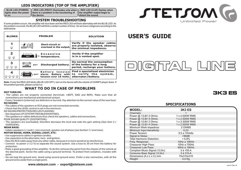
19) POWER LED (BLUE): The LED indicator lights up when the unit is triggered by the signal coming from the remote CD/MP3-
player.
20) PROT LED (RED): The LED will illuminate in the following situations:
a) Short-circuit the outputs speakers c) Low battery voltage
b) temperature above the allowed. d) High voltage battery
21) CLIP LED (RED): The LED lights up when the output signal start to distort.
The cables of the speakers should be polarized (marked) to facilitate the identification of positive and
negative. The circumference should be at least 10mm². Keep the cables from the speakers properly
insulated. Beware of metal parts that can damage the insulation of cables.
INSTALLATION OF OUTPUT SPEAKER
HIGH
PASS
FILTER
BASS
LOW
PASS
FILTER
MID
BASS
MID
HIGH
10Hz -10dB -10dB -10dB50Hz700Hz +10dB
0dB 0dB 0dB
+10dB +10dB15KHz
40Hz 90Hz60Hz 200Hz
OUTPUT
OVER
CLIP
OFF
ON
HIGH
PASS
FILTER
BASS
LOW
PASS
FILTER
MID
BASS
MID
HIGH
10Hz -10dB -10dB -10dB50Hz700Hz +10dB
0dB 0dB 0dB
+10dB +10dB15KHz
40Hz 90Hz60Hz 200Hz
OUTPUT
OVER
CLIP
OFF
ON
9K EQ - 2 OHMS / 2 x 4 Ohms
9K EQ - 1 OHM / 2 x 2 Ohms
9K EQ - 2 OHMS / 4 x 8 Ohms
9K EQ - 1 OHM / 4 x 4 Ohms
19
20
21
HIGH
PASS
FILTER
BASS
LOW
PASS
FILTER
MID
BASS
MID
HIGH
10Hz -10dB -10dB -10dB50Hz700Hz +10dB
0dB 0dB 0dB
+10dB +10dB15KHz
31 12
4 5 6 7 8 9 10 11
40Hz 90Hz60Hz 200Hz
1713 18
14 15 16
OUTPUT
OVER
CLIP
OFF
ON
2

