manuals.online logo
Brands
  1. Home
  2. •
  3. Brands
  4. •
  5. StetSom
  6. •
  7. Amplifier
  8. •
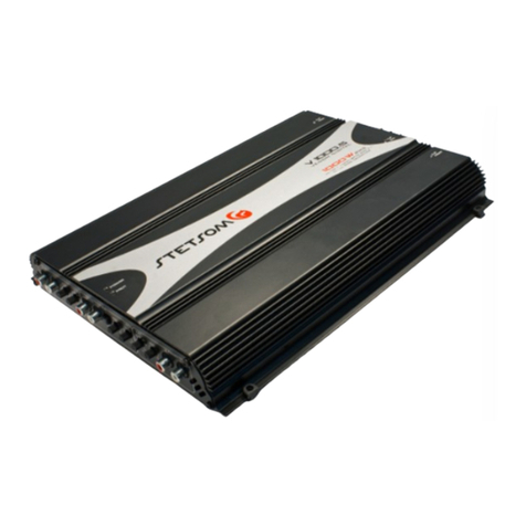
  9. StetSom V 1300.4 User manual

StetSom V 1300.4 User manual

4mH
INDUTOR
4mH
INDUTOR
REMOTE
(CD-PLAYER
/MP3-PLAYER)
30 cm
BATTERY
12 V
CHASSIS
1 Fuse 70A
2
2
2
2
22
1000uF/100V
1000uF/100V
H A L FH A L F
BRIDGEBRIDGE
H A L F
BRIDGE
VENOM LINEVENOM LINEVENOM LINE
V 1300.4V 1300.4
V 1800.4V 1800.4
V 1300.4
V 1800.4
USER’S GUIDE
TRI MODE
The Tri Mode allows the stereo and the bridge to be ON simultaneously. This way the switches are
kept in OFF position.
Phone: (786) 2651960 - www.stetsom.com - [email protected]
NOT TURN ON:
- The cables are not correctly connected (terminals BAT, GND and REM). Make sure that all connections
has mechanical and electrical contact.
- Fuses/circuit breakers (external) are defective or burned. Take care about the correct value of the
new fuse!
NO SOUND:
- The cables of speakers or plugs RCA are not connected correctly.
- Check if the LEVEL control is not in the minimum.
NO SOUND / RED LED (PROTECTION) ILLUMINATED:
- Speakers or cables (damaged), so, check speakers, cables and connections.
- Check the battery charge.
BAD SOUND QUALITY (DISTORTION):
- The speakers are overloaded, so, decrease the level and redo the gain adjustment (see iten 2/general
description).
WEAK BASS:
- Cables of speakers (+) and (-) are changed, speakers out of phase (see iten 5/general description).
HOW TO ACT IN CASE OF PROBLEMS
Note: If only the RED LED blinks (BLUE LED OFF), turn on the device with the volume of CD/MP3-player down. If
the problem persists, please contact us.
SYSTEM TROUBLESHOOTING “LED”
MODEL: V 1300.4 - 2 OHMS V 1800.4 - 2 OHMS
Channels: 4 4
Power @ 13.8V Stereo 2: 4 x 400 Watts RMS 4 x 500 Watts RMS
Power @ 13.8V Stereo 4: 4 x 260 Watts RMS 4 x 290 Watts RMS
Power @ 13.8V Bridge 4: 2 x 760 Watts RMS 2 x 1000 Watts RMS
Power @ 12.6V Stereo 2: 4 x 325 Watts RMS 4 x 450 Watts RMS
Power @ 12.6V Stereo 4: 4 x 220 Watts RMS 4 x 280 Watts RMS
Power @ 12.6V Bridge 4: 2 x 650 Watts RMS 2 x 900 Watts RMS
Minimum Output Impedance: 2 Ohms 2 Ohm
Input Impedance: 15K Ohms 15K Ohms
Minimum Input Sensitivity: 0,2V 0,2V
Total Harmonic Distortion: 0,9 % THD < 0,9 % THD
Signal to Noise: > 90 dB > 90 dB
Crossover HIGH PASS: 70 Hz to 700 Hz 70 Hz to 700 Hz
Crossover LOW PASS: 40 Hz to 700 Hz 40 Hz to 700 Hz
Frequency Resp. (-3dB) @ 2 : 10 Hz to 22 KHz 10 Hz to 22 KHz
Power: 9,5 to 15V 9,5 to 15V
Consumption Music Signal: 65A 65A
Consumo BASS Signal: 130A 130A
Dimensions (A x L x C): 40x240x365 mm 40x240x365 mm
Weght: 3,0 Kg 3,0 Kg
MAIO/2013 - R3
1 ou 2
1 ou 2
4
1 ou 2
1 ou 2
REMOTE
(CD-PLAYER
/MP3-PLAYER)
30 cm
BATTERY
12 V
CHASSIS
1 Fuse 70A
22
REMOTE
(CD-PLAYER
/MP3-PLAYER)
30 cm
BATTERY
12 V
CHASSIS
1 Fuse 70A
1 ou 2 2
REMOTE
(CD-PLAYER
/MP3-PLAYER)
30 cm
BATTERY
12 V
CHASSIS
1 Fuse 70A
1/10) INPUT – RCA R and L: This entry should receive the signal via RCA cable that should be
connected to the output RCA of CD/MP3-player. (1 REAR / 10 FRONT)
2/9) LEVEL – GAIN CONTROL: Controls the level of the input signal, allowing a proper adjustment to
any CD/MP3-player of the market. Can be regulated as follows:
a) at CD/MP3-player, put any musical signal and set the volume at 80% max.
For example: if the maximum volume of your CD/MP3-player is 45 (100%) , set to 36 (80%).
b) at amplifier, from the LEVEL in the minimum, increase gradually up until distort the signal.
c) slowly, return LEVEL until the signal is free of distortion. (2 REAR / 9 FRONT)
3/8) HIGH PASS FILTER: This control varies the filter cut off frequency from 15Hz to 2KHz. This filter
allows to pass sounds above the cut off frequency.(3 REAR / 8 FRONT)
4/7) CROSSOVER REAR/FRONT - KEY H.P.F/L.P.F/FLAT: This switch lets you choose which type
of CROSSOVER will be used by channels. (4 REAR / 7 FRONT)
5/6) LOW PASS FILTER: This control varies the filter cut off frequency from 50Hz to 15KHz. This
filter allows to pass sounds below the cut off frequency.
11) ENTRADA DE AR: Esta área deve ficar totalmente desobstruída, pois ela é a principal entrada de
ar frio do aparelho.
12/16) SAÍDA P/ ALTO-FALANTES: Devem ser ligadas aos alto-falantes com cabo paralelo
polarizado de bitola 4,0 mm² (mínimo). (12 FRONT / 16 REAR)
13) GND – EARTH CONNECTION: Use cable gauge of 21,0 mm² (AWG 4). Plug the cable into the
vehicle chassis.
OBS: Para prevenir ruídos, sempre ligue o fio GND (-) do CD/MP3-player, ou outros
aparelhos no mesmo ponto de aterramento do amplificador.
14) 6) REM – REMOTE ACTUATION: Connect the REM terminal to output remote/electrical antenna
of your CD/MP3-player. So, when turn on your CD/MP3-player, the amplifier will automatically turn
on too. Cable of 0.5 mm² is enough.
15) BAT – POSITIVE: Connect the terminal (BAT) to the positive pole of battery (+12V) with a cable
(gauge at least 21,0 mm² (AWG 4)). It is extremely important that use a fuse or breaker protection
in this cable with a maximum distance of 30 cm from the battery.
short-circuit the terminals of fuse, this may cause irrecoverable damage and loss of warranty.
18) PROTECTION INDICATOR LED (RED): This led will light up when:
a) Temperature is higher than allowed.
The sound is turned off: after the cooling-off reset the CD/MP3-PLAYER and the sound will work
again.
b) Overload or short circuit in the speakers outputs.
The sound will be turned off so the equipment won’t be damaged. Check all the
loudspeakers wires to solve the problem. Check the minimum acceptable impedance as well.
17) ON INDICATOR LED (BLUE): This led will light up when the equipment is started by an in-
coming CD/MP3-player remote signal.
H.P.F L.P.F
FLAT
H.P.F. X-OVER L.P.F. L.P.F. X-OVER H.P.F.
L.P.F H.P.F
FLAT
0 100
LEVEL
0 100
LEVEL
1
4
56 7 8 9
3
210
18
11 14
12 13 15 16
17
3 CHANNELS MODE (2 STEREO + 1 BRIDGE)
It is suggested when a complete system using only one amplifier is desired. The minimum impedance required for
the front speakers is 1 ohm for each channel, a 2 ohms one is acceptable though. The minimum subwoofer
impedance must be 2 ohms.
2 CHANNELS MODE (BRIDGE)
The amplifier can work in the bridge mode getting the power of 1 channel together in a single speaker. The
minimum speaker impedance must be 2 Ohms.
4 CHANNELS MODE
The minimum required speakers impedance is 1 Ohm for each channel; a 2 Ohms one is acceptable though. The
connections in 4 channels mode are::
INSTALLATION OUTPUT OF SPEAKERS
The amplifier can work with 2, 3 or 4 independent channels the speaker impedance varies from 1 to 4
ohms according to the chosen mode. Be aware of the correct polarity when installing the speakers.
The speaker power must be at least the same as the power delivered by amplifier channel. Notice that
the power output is stronger in 1 Ohm speakers and weaker in 2 Ohms speakers. When using the BRIDGE
connection, the power will also be stronger than in stereo mode. Use 4 mm² gauge cables with up to 3m length.
AUDIO INPUT AND CONTROLS
OVERVIEW
OUTPUT AMPLIFIED AUDIO AND POWER INPUT.
This manual suits for next models

1

Other StetSom Amplifier manuals

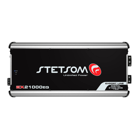
StetSom 9K EQ User manual

StetSom

StetSom 9K EQ User manual

StetSom EXPORT LINE EX5000EQ User manual

StetSom

StetSom EXPORT LINE EX5000EQ User manual

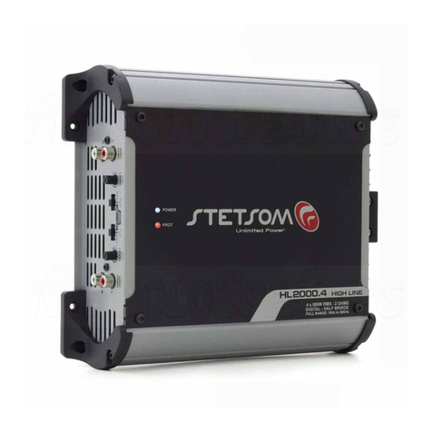
StetSom HIGH LINE HL2000.4 User manual

StetSom

StetSom HIGH LINE HL2000.4 User manual

StetSom Bravo BASS Flex 3K User manual

StetSom

StetSom Bravo BASS Flex 3K User manual

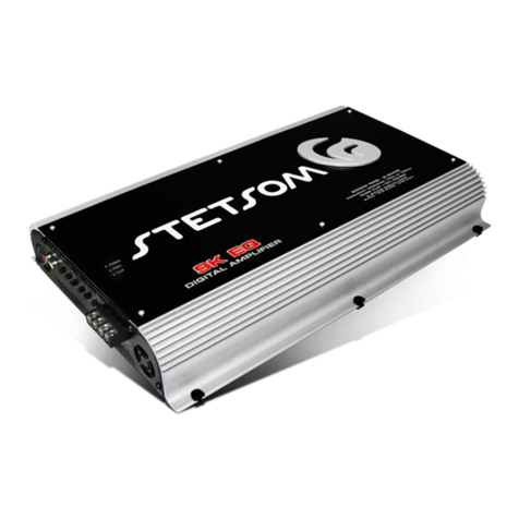
StetSom Venom V 1000.5 User manual

StetSom

StetSom Venom V 1000.5 User manual

StetSom V 1000.5 - STEREO User manual

StetSom

StetSom V 1000.5 - STEREO User manual

StetSom IR100.1 RCA User manual

StetSom

StetSom IR100.1 RCA User manual

StetSom Vulcan 8000 User manual

StetSom

StetSom Vulcan 8000 User manual

StetSom DIGITAL BASS DB2000 User manual

StetSom

StetSom DIGITAL BASS DB2000 User manual

StetSom HIGH LINE 1200.4 User manual

StetSom

StetSom HIGH LINE 1200.4 User manual

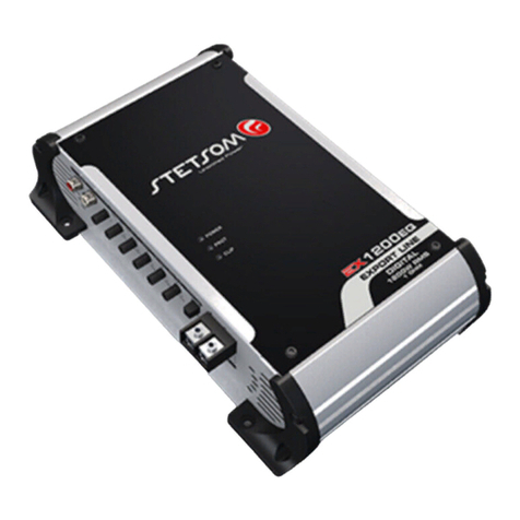
StetSom Export Line EX 1200EQ User manual

StetSom

StetSom Export Line EX 1200EQ User manual

StetSom EXPORT LINE EX1600EQ User manual

StetSom

StetSom EXPORT LINE EX1600EQ User manual

StetSom HIGH LINE 1000.2 User manual

StetSom

StetSom HIGH LINE 1000.2 User manual

StetSom Digital 3K3 ES User manual

StetSom

StetSom Digital 3K3 ES User manual

StetSom HIGH LINE HL400.4 User manual

StetSom

StetSom HIGH LINE HL400.4 User manual

StetSom 3K7 ES User manual

StetSom

StetSom 3K7 ES User manual

StetSom Export Line EX8000EQ User manual

StetSom

StetSom Export Line EX8000EQ User manual

StetSom EX3000 User manual

StetSom

StetSom EX3000 User manual

StetSom BRAVO FULL 3000 User manual

StetSom

StetSom BRAVO FULL 3000 User manual

StetSom EXPORT EX10500EQ User manual

StetSom

StetSom EXPORT EX10500EQ User manual

StetSom R400.4 User manual

StetSom

StetSom R400.4 User manual

StetSom BRAVO Full 2000 User manual

StetSom

StetSom BRAVO Full 2000 User manual

StetSom BRAVO HQ 800.4 User manual

StetSom

StetSom BRAVO HQ 800.4 User manual

StetSom DB500.1 User manual

StetSom

StetSom DB500.1 User manual

Popular Amplifier manuals by other brands

Atlantic HAL 1200 user manual

Atlantic

Atlantic HAL 1200 user manual

Teac Tascam MA-BT240 owner's manual

Teac

Teac Tascam MA-BT240 owner's manual

Detector PC2003 Programming manual

Detector

Detector PC2003 Programming manual

SmoothTalker BST1900 User instruction manual

SmoothTalker

SmoothTalker BST1900 User instruction manual

OSD Audio PAM 245 instruction manual

OSD Audio

OSD Audio PAM 245 instruction manual

RDL EZ-HDA4B Installation and operation manual

RDL

RDL EZ-HDA4B Installation and operation manual

Kenwood KAC-5001PS instruction manual

Kenwood

Kenwood KAC-5001PS instruction manual

ACL VC PANNING AMPLIFIER user manual

ACL

ACL VC PANNING AMPLIFIER user manual

OSD Audio SMPS500DSP user manual

OSD Audio

OSD Audio SMPS500DSP user manual

crescendo Evolution Seven 7A2 instruction manual

crescendo

crescendo Evolution Seven 7A2 instruction manual

Plinius Odeon instruction manual

Plinius

Plinius Odeon instruction manual

Viking PA-15 product manual

Viking

Viking PA-15 product manual

Electro-Voice CPS 4 owner's manual

Electro-Voice

Electro-Voice CPS 4 owner's manual

Marantz PM7200N1B Service manual

Marantz

Marantz PM7200N1B Service manual

Bell SMP QX Series manual

Bell

Bell SMP QX Series manual

PAC AP4-FD21 manual

PAC

PAC AP4-FD21 manual

Yamaha AX-890 owner's manual

Yamaha

Yamaha AX-890 owner's manual

Roland CUBE-STEX Service notes

Roland

Roland CUBE-STEX Service notes

manuals.online logo
manuals.online logoBrands
  • About & Mission
  • Contact us
  • Privacy Policy
  • Terms and Conditions

Copyright 2025 Manuals.Online. All Rights Reserved.