Stieber Clutch GFR Series User manual
STIEBER GmbH
PO Box 10 53 80
D-69043 Heidelberg, Tel +49 (0)6221 30 47 0, Fax +49 (0)6221 30 47 31
last changes 24.09.2009 page 1/4
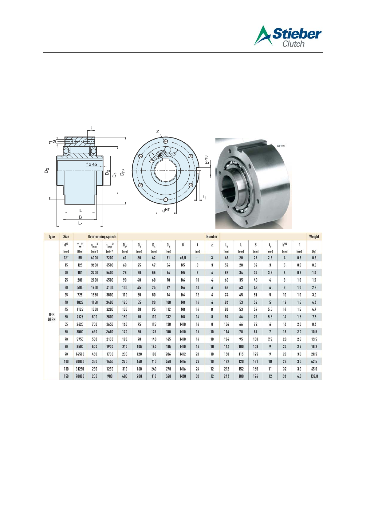
Installation and Maintenance Instructions Freewheel Type GFRN
To avoid premature failure of the freewheel or possible machine malfunction, installa-
tion of the freewheel should be carried out by suitably qualified personnel and accord-
ing to the following instructions.
STIEBER will not accept liability in cases of non-compliance with these instructions!
Description:
Freewheels of type GFRN are designed primarily for oil lubrication, and may be used as ei-
ther backstops or overrunning clutches.
The main components are: Outer race, inner race, ball bearings, drive rollers and spring
elements.

STIEBER GmbH
PO Box 10 53 80
D-69043 Heidelberg, Tel +49 (0)6221 30 47 0, Fax +49 (0)6221 30 47 31
last changes 24.09.2009 page 2/4
The basic GFRN unit may be fitted with two covers of types F1 to F7. The GFRN can be in-
stalled so that either the inner or outer race overruns. The maximum overrunning speeds
quoted in table 2 must not be exceeded.
Prior to Installation:
The freewheels should be unpacked and installed in a clean dry working environment.
For units despatched ‘dry’ the corrosion inhibitor should be removed using flushing oil.
Care must be taken that the ball bearings are not loaded radially or axially during installation.
The shaft should be to h6 or j6 tolerance. The mounting register for the outer race should be
to H7 or G7 tolerance.
The freewheeling direction should be checked prior to installation.
To reverse the freewheeling direction of a unit fitted with covers, simply remove the cover-
plates, and re-install at opposite ends of the freewheel. Tighten the bolts to the torque speci-
fied in table 1 below. The bolts supplied are of 10.9 quality.
The outer race must not be moved axially if covers are not installed.
Ensure the oil bores in plate F6 are accessible for re-lubrication.
CAUTION: RISK OF INJURY!
When cover plates are removed, the freewheel should always be held so that the bore
is horizontal, otherwise the inner race and bearings may slip from the outer race.
Installation:
The unit should be installed as an assembly.
•For installation of the outer race into its housing, remove cover F6, the screws of which
have not been secured with Loctite.
•Insert the key, install the outer race and re-install the covers.
•Tighten bolts to the torque specified in table 1 below, and secure them with Loctite 243 or
equivalent.
•Install the inner race on to the shaft ensuring alignment of the keyways. Apply any axial
load exclusively to the inner race. The inner race must be retained axially on the shaft -
circlips or a retainer plate are suitable.
Table 1:
8.8 10.9 Size Tightening Torque
[Nm]
12 - 20 M5 5,9 8,3 10 4,5
25 - 30 M6 9,9 14 16,5 7
40 - 50 M8 24 34 40 18
55 - 80 M10 47 66 79 33
90 M12 82 115 140 63
100 - 130 M16 200 280 340 150
150 M20 390 550 660 300
Oil Plugs
Tightening Torque
[Nm] ± 7%
Bolt Size
Bore Ø
[mm]

STIEBER GmbH
PO Box 10 53 80
D-69043 Heidelberg, Tel +49 (0)6221 30 47 0, Fax +49 (0)6221 30 47 31
last changes 24.09.2009 page 3/4
After Installation:
After installation, ensure the unit freewheels in the required direction.
Prior to use check that the oil is to the correct level.
The drag torque produced when freewheeling is about1/1000 of the nominal torque.
Dismantling:
To remove the unit please follow the installation section in reverse sequence.
Table 2 (Based on oil lubrication):
without sealing with sealing without sealing with sealing
12 110 4000 3100 7200 4700
15 250 3600 2800 6500 4400
20 262 2700 2400 5600 4100
25 576 2100 1600 4500 3800
28 1000 1700 1300 4100 2800
30 1000 1700 1300 4100 2800
35 1450 1550 1200 3800 2600
40 2050 1150 850 3400 2300
45 2250 1000 740 3200 2200
50 4250 800 580 2800 1950
55 5250 750 550 2650 1800
60 7000 650 530 2450 1700
70 11500 550 500 2150 1600
80 17000 500 480 1900 1500
90 29000 450 450 1700 1300
100 40000 350 350 1450 1100
130 62500 250 250 1250 900
150 140000 200 200 980 700
Size max. Torque
[Nm]
Overrunning Speed
Inner Race
[rpm]
Overrunning Speed
Outer Race
[rpm]
Lubrication and Maintenance:
Freewheels supplied with F5 and F6 covers fitted may be factory filled with oil. The oil used
has a viscosity of ISO-VG 32. An oil change may be necessary according to the application
details. Recommended lubricants are specified in the table below.
To check oil level
The cover plate F6 has 3 oil bores at the circumference.
To check oil level, the oil bores should be at 12 o'clock 6 o'clock and 8 (or 4) o'clock.
•Remove top and lateral oil plug. Top up until oil seeps from the lateral hole.
•Tighten all plugs to the torque specified in the table 1 above.
•For oil change remove all oil plugs to drain oil.
•Refill as described above.

STIEBER GmbH
PO Box 10 53 80
D-69043 Heidelberg, Tel +49 (0)6221 30 47 0, Fax +49 (0)6221 30 47 31
last changes 24.09.2009 page 4/4
•The lubricating oil should be changed after approximately 10 hours operation. Further oil
changes should be made after every 2000 hours.
In arduous applications change oil every 1000 operating hours.
•With ambient temperatures above 80°C, check lubrication regularly.
•For operating temperatures below -20°C and above 100°C contact the technical depart-
ment of your lubricant suppliers.
•For indexing applications, oil types with a kinematic viscosity of about 10mm2/s at the
normal operating temperature are recommended.
Lubricants with slip additives such as graphite, Molykote or similar agents should be
avoided
Grease Lubrication
If grease lubrication is to be used please consult your STIEBER stockist.
Drain existing oil first. 30 to 40% of the free space between the races should be grease filled,
the bearings have to be lubricated too. Excessive grease may lead to malfunction of the
freewheel! Every two years the grease has to be changed and the freewheel to be inspected.
With grease lubrication the overrunning speed must not exceed 50% of the speeds specified
in table 2.
Recommended Lubricants
-40°C to- 15°C -15°C to +15°C +15°C to +30°C +30°C to +50°C
-20°C to +20°C +10°C to +50°C +40°C to +70°C +50°C to +85°C Grease
ISO - VG
DIN 51519 10 22 46 100
ARAL SUMOROL CM10 SUMOROL CM22 MOTANOL HK46 DEGOL CL100T ARALUB HL2
BP ENERGOL CS10 ENERGOL CS22 ENERGOL CS46 ENERGOL RC100 ENERGREA SE LS2
DEA ASTRON HL10 ASTRON HL22 ASTRON HL46 ASTRON HL100 GLISSANDO 20
ESSO NUTTO H10
SPINESSO 10 NUTTO H22
SPINESSO 22 NUTTO H46
TERESSO 46 NUTTO H100 BEACON 2
FUCHS RENOLIN MR3 RENOLIN DTA22 RENOLIN DTA46 RENOLIN MR30 RENOLIT LZR2
KLÜBER CRUCOLAN 10 CRUCOLAN 22 CRUCOLAN 46 CRUCOLAN 100 POLYLUB WH2
MOBIL VELOCITE No6 VELOCITE No10 VACTRA MEDIUM VG46 VACTRA HEAVY VG100 MOBILUX 2
SHELL MORLINA 10 MORLINA 22 MORLINA 46 MORLINA 100 ALVANIA G2
TOTAL AZZOLA ZS10 AZZOLA ZS22 AZZOLA ZS46 AZZOLA ZS100 MULTIS 2
Ambient temperature
Operating temperature
Oil
The ambient temperature is to be taken as a guide line. The operating temperature is deter-
minant for the choice of the viscosity.
Corrosion inhibitor: Rivolta KSP
Time of protection: 6 to 12 months
Recommendation: Prior to use, remove corrosion inhibitor using flushing oil.
The maximum overrunning speeds given in our literature apply to oil lubricated units.
For grease lubrication the quoted speeds must be halved.
Please refer to the ‘Lubrication & Maintenance’ section in our main catalogue.
This manual suits for next models
1
Other Stieber Clutch Industrial Equipment manuals


