Stieber Clutch RSXM Series Quick guide

Assembly and maintenance manual
Type RSXM31-RSXM101
Rev.0
08.07.14
Hatschekstr.36
69126 Heidelberg
Germany
Phone +49(0)6221 30470
Fax +49(0)6221 304731
www.stieber.de
Stieber Clutch Page 2/21
M1016E_0 Assembly and maintenance manual
WARNING!
Risk of injury due to moving components!
Rotating driven components can cause the most severe injuries.
Therefore, during operation:
It is strictly forbidden for persons to loiter in the danger zone
or in its immediate vicinity.
Do not disable, render unusable or circumvent safety
equipment and / or safety functions.
Prior to entering the danger zone:
Switch off the power supply and secure it against being
switched on again.
Wait for lagging components to come to a standstill.
DANGER!
Danger due to improper operation!
Modifications to
the one-way clutch are not permitted and
may impair safety.
All tasks may only be performed by personnel with the req-
uisite training and expertise.
Repairs and maintenance tasks may only be performed
when the machine is at a standstill. To this end, the
machine is to be secured against a restart.
WARNING!
Risk of injury due to incorrect assembly!
Faulty installation and maintenance can cause severe property
damage and personal injury.
Installation, maintenance and repair work may only be performed
by personnel with the requisite training and expertise.
WARNING! Risk of injury for insufficiently qualified personnel!
Improper handling can cause significant personal injury and
property damage. Therefore:
Only ever have tasks performed by those persons to whom the
tasks have been assigned.
Table of contents Page
General safety instructions...................................................................................................2
1General.............................................................................................................................4
1.1 Information relating to the assembly and maintenance manual.................................4
1.2 Explanation of symbols ..............................................................................................4
1.3 Manufacturer..............................................................................................................5
1.4 Labeling .....................................................................................................................5
General safety instructions

Stieber Clutch Page 3/21
M1016E_0 Assembly and maintenance manual
1.5 Environmental protection ...........................................................................................5
2Safety ...............................................................................................................................5
2.1 Intended use ..............................................................................................................5
2.2 Responsibility of the operator ....................................................................................6
2.3 Assembly and maintenance personnel ......................................................................6
2.4 Personal protective equipment ..................................................................................7
2.5 Limitations of use .......................................................................................................7
3Structure and function....................................................................................................8
3.1 Structure ....................................................................................................................8
3.2 Function .....................................................................................................................8
4Transport and packaging...............................................................................................9
5Storage...........................................................................................................................10
5.1 Short-term storage ...................................................................................................10
5.2 Long-term storage....................................................................................................10
6Installation.....................................................................................................................11
6.1 Checking the direction of rotation ............................................................................11
6.2 Lubrication ...............................................................................................................12
6.2.1 Operation with oil lubrication.............................................................................12
6.2.2 Operation with grease lubrication .....................................................................13
6.3 Assembly .................................................................................................................14
6.4 Mounting example....................................................................................................15
7Maintenance ..................................................................................................................15
7.1 Disassembly in case of maintenance.......................................................................16
7.2 Test criteria in case of maintenance ........................................................................16
7.3 Assembly in case of maintenance when using grease lubrication...........................17
7.4 Assembly in case of maintenance when using oil lubrication ..................................18
8Disassembly..................................................................................................................19
9Disposal.........................................................................................................................20
10 Faults..............................................................................................................................20
11 Spare parts ....................................................................................................................20
12 Appendix........................................................................................................................20
12.1 Layout drawing RSXM31-RSXM101........................................................................21

Stieber Clutch Page 4/21
M1016E_0 Assembly and maintenance manual
1.1 Information relating to the assembly and maintenance manual
This assembly and maintenance manual provides important information regarding the
installation and commissioning of the one-way clutch.
Prerequisite for safe operation is compliance with all of the stated safety and handling
instructions.
Moreover, the relevant local accident protection guidelines and general safety provisions for
the field of application of the one-way clutch are to be complied with.
Read the assembly and maintenance manual carefully prior to installation and
commissioning. It is a product component and must be kept in the immediate vicinity of the
installation site and be accessible to personnel at all times. Furthermore, all safety
instructions stated in the assembly and maintenance manual are to be observed.
1.2 Explanation of symbols
Warnings are marked throughout this assembly and maintenance manual by symbols. These
warning symbols are introduced by signal words which indicate the extent of the danger.
Comply with these warning symbols under all circumstances and act with due care and
attention to avoid accidents, personal injury and property damage.
DANGER! ...indicates an imminently dangerous situation which can be
fatal or cause severe injuries if it is not averted.
WARNING! ...indicates a potentially dangerous situation which can be
fatal or cause severe injuries if it is not averted.
ATTENTION! ...indicates a potentially dangerous situation which can
cause minor or light injuries if it is not averted.
CAUTION! ...indicates a potentially dangerous situation which can
cause property damage if it is not averted.
NOTE! … highlights helpful tips and recommendations as well as
information for efficient and fault-free operation.
1 General

Stieber Clutch Page 5/21
M1016E_0 Assembly and maintenance manual
1.3 Manufacturer
STIEBER GmbH, D-69126 Heidelberg, Hatschekstr. 36, Germany
Phone +49 (0) 6221 3047-0, Fax -31
1.4 Labeling
Front face of the outer race
Manufacturer’s name
Type designation
Date of manufacture (coded)
1.5 Environmental protection
Energy: The one-way clutch does not use any electrical energy
Materials: Steel
Recycling: Steel parts are up to 100% recyclable
2.1 Intended use
One-way clutches of type RSXM31-RSXM101 are directional clutches, engaged and
disengaged automatically, depending on the relative direction of rotation.
The torque is transmitted by a force-locking connection. They can be used as overrunning
clutches or backstops in machinery and equipment.
Driving operation of an overrunning clutch:
When operating in torque transmission mode the driving machine element and the driven
member are connected in a force-looking manner. In this operating state, a torque will be
transferred.
Overrunning operation of an overrunning clutch:
The overrunning clutch disengages automatically when the driven member rotates faster
than the driving member.
The contact-free operation will be ensured, when the driven member connected with the
inner race runs above a defined speed. From this speed up the wear-free operation of all
function-relevant components is guaranteed.
Lockout mode of a one-way clutch:
When operating in the locking direction of the one-way clutch, the machine shaft and the
torque bracing to the machine element are connected in a force-looking manner.
In this operating state, a torque will be transferred.
2 Safety

Stieber Clutch Page 6/21
M1016E_0 Assembly and maintenance manual
Overrunning mode of a one-way clutch:
The one-way clutch disengages automatically the force-locked connection between the
machine shaft and the torque bracing to the machine element, when the machine shaft runs
in freewheeling direction. The contact-free operation will be ensured, when the machine shaft
is rotating above a defined speed. From this speed up the wear-free operation of all function-
relevant components is guaranteed.
2.2 Responsibility of the operator
The operator of the machine, in which the one-way clutch is installed, is subject to the legal
obligations concerning occupational safety.
The valid provisions for the site of operation as well as the safety and accident prevention
regulations of the trade associations are to be observed. This, in particular, means that the
operator:
is aware of the valid occupational safety provisions.
implements the necessary behavioral requirements for operation of the machine, in
which the one-way clutch is installed, at the site of operation.
clearly defines responsibilities for installation, operation, maintenance and cleaning
of the machine in which the one-way clutch is installed.
ensures that all staff members, who work at or with the machine in which the one-
way clutch is installed, are employed and have read and understood the operating
manual. Moreover, he must, at regular intervals, provide training for personnel on
how to handle the machine, in which the one-way clutch is installed, and inform
them of the potential dangers. In addition, the operator is responsible for ensuring
that the machine in which the one-way clutch is installed:
ois always in perfect technical condition.
ois maintained in accordance with the specified maintenance intervals.
ohas all its safety equipment checked regularly for completeness and
functionality.
2.3 Assembly and maintenance personnel
WARNING
Risk of injury for insufficiently qualified personnel!
Improper handling can cause significant personal injury and proper-
ty damage. Therefore:
Only ever have tasks performed by those persons to whom the
tasks have been assigned.
Qualified personnel are those persons who, owing to their training, experience and
instruction as well as their knowledge of relevant standards, provisions, accident prevention
regulations and operating conditions, have been authorized by the person responsible for the
safety of the plant to perform the requisite tasks and are able to recognize and avoid
potential dangers in doing so. Knowledge of first-aid measures and on-site emergency
equipment must also be included.

Stieber Clutch Page 7/21
M1016E_0 Assembly and maintenance manual
2.4 Personal protective equipment
It is necessary to wear personal protective equipment when handling the machine, in which
the one-way clutch is installed, to minimize health risks.
The necessary protective equipment such as work shoes, gloves, safety goggles etc. is to be
put on prior to all tasks and kept on during the task.
2.5 Limitations of use
Type
maximum
torque
[Nm]
Overrunning
speeds
[rpm]
maximum
allowable
torque
transmission
speed
[rpm]
admissible
runout (T.I.R.)
outer race
to shaft
[mm]
admissible
axial run-out
outer race
to shaft
[mm]
Number/
size
fixing screws
Bore dia.
[mm]
min. max.
31 20 200 820 20000 340 0,2 0,1
6 x M6
38 20,25 270 770 18500 320 0,2 0,1
6 x M6
46 25,30 850 530 13500 300 0,2 0,1
6 x M6
51 35,40 1050 525 12500 220 0,2 0,1
6 x M6
56 35,40 1250 500 11500 210 0,2 0,1
8 x M6
61 35,40 840 640 14000 265 0,2 0,1
6 x M8
66 35,40,45 1700 480 10000 200 0,2 0,1
8 x M8
76 40,45,50 2200 460 9000 190 0,2 0,1
8 x M8
86 45,50 2900 440 8000 180 0,2 0,1
8 x M8
101 45,55,60,70 3900 420 6500 175 0,2 0,1
8 x M10
Limits for ambient temperature: from –20°C to +50°C
Maximum operating temperature: 90°C
Overrunning: Machine shaft (inner race)
Required machine shaft tolerance: Ø h6 or j6
Required tolerance outer race centering (inner diameter) :
ØH6orG6
Oil lubrication: approved oils according Stieber catalogue / WN900
Grease lubrication: approved greases according Stieber catalogue / WN900
Stieber Clutch Page 8/21
M1016E_0 Assembly and maintenance manual
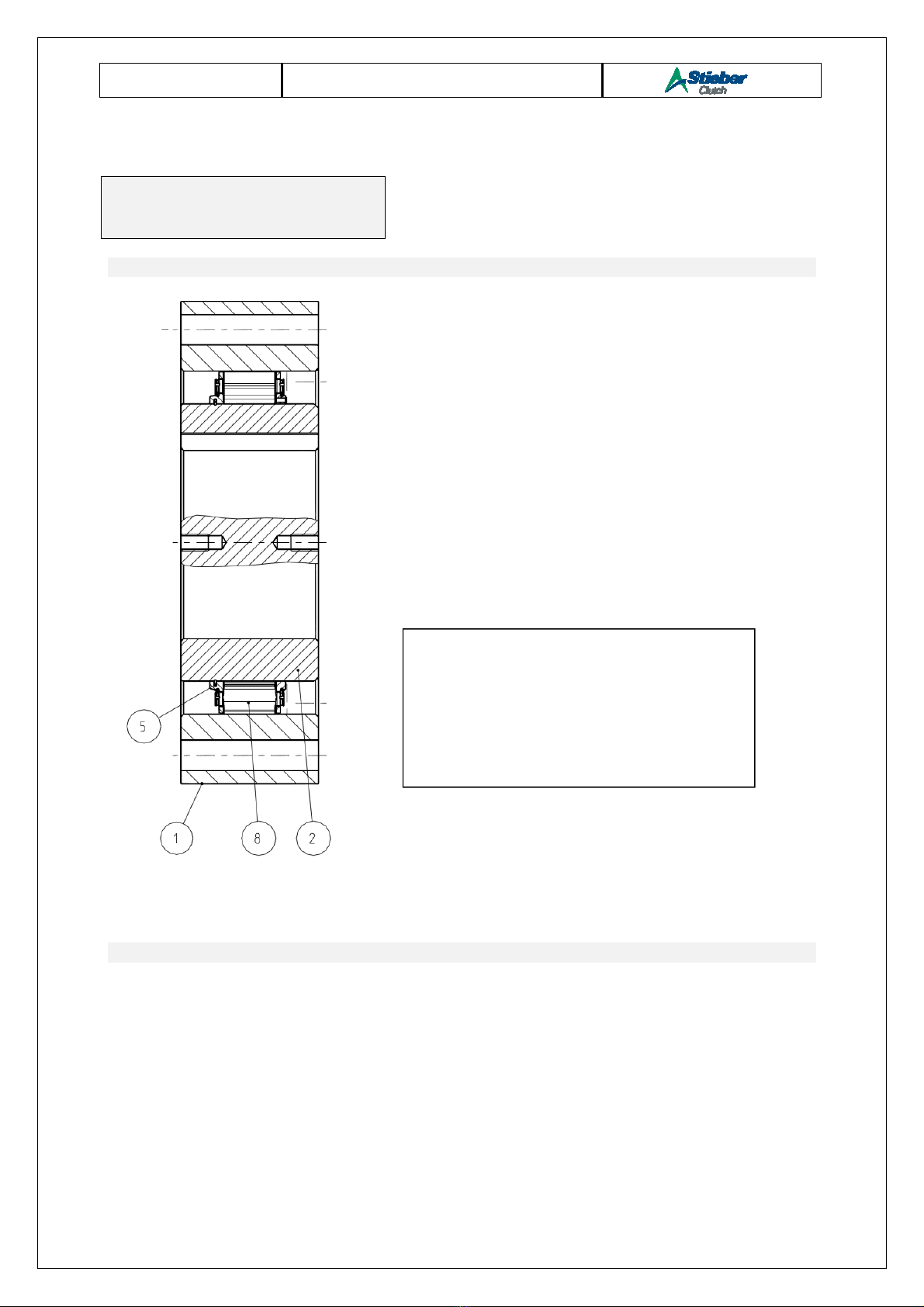
3.1 Structure
Fig. 1 Structure
3.2 Function
When the torque is transmitted through the one-way clutch, the outer race (1) and the inner
race (2) are coupled in a force-locked manner (see Fig. 2). For this purpose, clamping
elements are used, the outer contours of which generates the force-locked coupling. The
clamping elements are integrated into a cage (8) and are energized by springs into contact
with the outer and inner race. The springs ensure rapid responding behavior of the one-way
clutch at the start of torque transmission.
3 Structure and function
Freilaufkupplung
Pos. 1 Outer race
Pos. 2 Inner race
Pos. 8 Cage
Pos. 5 Spring

Stieber Clutch Page 9/21
M1016E_0 Assembly and maintenance manual
Fig.2 Torque transmission
In overrun operation, above the minimum permissible overrunning speed, the centrifugal
force, in connection with the geometry of the clamping elements, generates a force which
turns the clamping elements against the spring force (see Fig. 3). A contact-free position is
brought about in this way so that wear-free operation of the one-way clutch can be achieved.
The minimum permissible overrunning speed may only be lower for a short period during the
start-up or shut-down stage otherwise the damage to the contact partner caused by wear
and tear may lead to the failure of the one-way clutch.
Fig.3 Contact-free position
NOTE The local provisions regarding the disposal of transport and
packaging materials are to be observed.
One-way clutches of Type RSXM31-RSXM101 are packaged in non-absorbent corrosion
protection paper. All components are sent in a box.
To prevent the component from breaking or falling apart they are fixed with a cable clip.
4 Transport and packaging

Stieber Clutch Page 10/21
M1016E_0 Assembly and maintenance manual
Transport damage to the packaging and / or the one-way clutch is to be reported to the
respective transit company!
The one-way clutch must be unpacked in a clean and dry environment!
5.1 Short-term storage
One-way clutches of Type RSXM31-RSXM101 come with an oil film as corrosion protection.
This corrosion protection is to be renewed at regular intervals. The frequency of these
renewal intervals is dependent on the environmental conditions (temperature, moisture, salt
content of the air, etc.) at the storage site.
The maximum storage period (short-term storage) is 6 months. Moreover, the one-way clutch
must have long-term storage corrosion protection applied to it.
Store packages under the following conditions:
Do not keep outdoors.
Keep dry and free from dust.
Do not expose to aggressive media.
Keep away from direct sunlight.
Avoid mechanical shocks and vibrations.
Storage temperature: −10 to +60 °C.
Relative humidity: maximum 95%, non-condensing.
5.2 Long-term storage
To this end the one-way clutch must be welded in PE foil with desiccant agent. The corrosion
protection must be checked after a period not exceeding one year or else depending on the
environmental conditions (temperature, moisture, salt content of the air, etc.) at the storage
site.
Store packages under the following conditions:
Do not keep outdoors.
Keep dry and free from dust.
Do not expose to aggressive media.
Keep away from direct sunlight.
Avoid mechanical shocks and vibrations.
Storage temperature: −10 to +60 °C.
Relative humidity: maximum 95%, non-condensing.
5 Storage

Stieber Clutch Page 11/21
M1016E_0 Assembly and maintenance manual
6.1 Checking the direction of rotation
WARNING
Risk of injury due to incorrect assembly!
Faulty installation and maintenance can cause severe property
damage and personal injury.
Installation, maintenance and repair work may only be performed
by personnel with the requisite training and expertise.
WARNING
Risk of injury due to moving components!
Rotating driven components can cause the most severe injuries.
Therefore, during operation:
It is strictly forbidden for persons to loiter in the danger zone
or in its immediate vicinity.
Do not disable, render unusable or circumvent safety
equipment and / or safety functions.
Prior to entering the danger zone:
Switch off the power supply and secure it against being
switched on again.
Wait for lagging components to come to a standstill.
CAUTION
Risk of injury due to falling components!
The outer race or inner race can fall down if the transportation lock
has been removed.
Fasten the outer / inner race axially.
The direction of rotation at idle speed is marked as FREE on the cage (8). The direction of
rotation can be changed by turning the inner race (2) including cage (8).
Procedural steps:
Place the one-way clutch facing upward the label "FREE" on an assembly table
Remove the cable clip
Lift the inner race (2) including the cage (8) out of the outer race (1). Use
appropriate lifting gear at the threaded hole of the inner race for this
Place the inner race (2) including the cage (8) facing downwards the label "FREE"
on an assembly table
Secure (see Fig. 4 and 5) the clamp bodies in lift-off position (against the spring
force) using an O-ring / cable connector as an assembly aid
6 Installation
Stieber Clutch Page 12/21
M1016E_0 Assembly and maintenance manual
Insert the inner race (2) with cage (8) into the outer race (1) until half of the clamp
body is covered
NOTE
The assembly aid (O-ring / cable connector) must be completely
removed. Non-observance of this note can cause functional
impairment and even failure.
Remove the assembly aid (O-ring / cable connector) completely and lower the inner
race and cage completely.
Check overrunning. The one-way clutch must be able to be turned easily in the
overrun direction of rotation.
6.2 Lubrication
One-way clutches of Type RSXM31-RSXM101 do not require any lubrication in overrun
operation above the lift-off speed as they operate without contact.
Similarly, no lubrication is required in lockout operation as only a minimal degree of rolling
motion in the clamp bodies occurs.
Additional lubrication is required if the one-way clutch runs with frequently repeated or
permanent working cycles below the lift-off speed. To this end, a lubricating film, which coats
the clamp bodies and tracks of the outer race, is mandatory. The lifetime is limited under
these operating conditions!
6.2.1 Operation with oil lubrication
An oil mist is sufficient for mounting inside a gear box.
If the one-way clutch runs with frequently repeated or permanent working cycles below the
lift-off speed, splash lubrication or oil supply between the cage and the outer track is
necessary. The lifetime is limited under these operating conditions!
The oil volume which is necessary for splash lubrication depends on the surrounding
construction.
Figure 5: Clamp bodies “after lift-off”
Figure 4: Clamp bodies “neutral position“

Stieber Clutch Page 13/21
M1016E_0 Assembly and maintenance manual
The level should be up to a maximum of 10 mm to an inside diameter of the outer race.
6.2.2 Operation with grease lubrication
NOTE Excessive lubrication may negatively affect the one-way clutch
functionality! Note the required grease quantities!
NOTE Unsuitable lubricants can negatively affect the one-way clutch func-
tionality! Only use greases approved by Stieber!
Select only lubricating greases complying with product catalogue/ Stieber WN900.
Procedural steps for greasing:
Place the one-way clutch facing upward the label "FREE" on an assembly table
Remove the cable clip
Lift the inner race (2) including the cage (8) out of the outer race (1). Use
appropriate lifting gear at the threaded hole of the inner race for this
Grease the outer track with a layer thickness of approx. 1 mm
oUse grease of NLGI class 000 to 2 with a maximum base oil viscosity
of 42 mm2/s
Secure (see Fig. 5 and 6) the clamp bodies in lift-off position (against the spring
force) using an O-ring / cable connector as an assembly aid
Insert the inner race (2) with cage (8) into the outer race (1) until half of the clamp
body is covered
NOTE
The assembly aid (O-ring / cable connector) must be completely
removed. Non-observance of this note can cause functional
impairment and even failure.
Remove the assembly aid (O-ring / cable connector) completely and lower the inner
race and cage completely.
Check overrunning. The one-way clutch must be able to be turned easily in the
overrun direction of rotation.
Stieber Clutch Page 14/21
M1016E_0 Assembly and maintenance manual
6.3 Assembly
WARNING
Risk of injury due to incorrect assembly!
Faulty installation and maintenance can cause severe property
damage and personal injury.
Installation, maintenance and repair work may only be performed
by personnel with the requisite training and expertise.
WARNING
Risk of injury due to moving components!
Rotating driven components can cause the most severe injuries.
Therefore, during operation:
It is strictly forbidden for persons to loiter in the danger zone
or in its immediate vicinity.
Do not disable, render unusable or circumvent safety
equipment and / or safety functions.
Prior to entering the danger zone:
Switch off the power supply and secure it against being
switched on again.
Wait for lagging components to come to a standstill.
CAUTION
Risk of injury due to falling components!
The outer race or inner race can fall down if the transportation lock
has been removed.
Fasten the outer / inner race axially.
Procedural steps :
Lift up the one-way clutch using suitable lifting gear and push it onto the oiled
machine shaft
Remove the cable clip
Fasten the one-way clutch axially on the machine shaft
Center the outer race in the torque-supporting machine element
NOTE Screw qualities 12.9 must not be used!
Secure the outer race in the torque-supporting machine element with the
appropriate fixing screws (e.g. as per standard DIN EN ISO 4762) and with screw
quality 10.9 or 8.8; tightening torque (see Table Tightening torque)
Tightening torque [Nm]
Size 8.8 10.9
M6 10 14
M8 25 34
M10 48 68
Table: Tightening torque (according VDI 2230 Sheet1, µ=0.12 metric standard thread)

Stieber Clutch Page 15/21
M1016E_0 Assembly and maintenance manual
Check overrunning. The one-way clutch must be able to be turned easily in the
overrun direction of rotation.
6.4 Mounting example
Figure 6: Mounting at the end of the shaft
WARNING
Risk of injury due to incorrect assembly!
Faulty installation and maintenance can cause severe property
damage and personal injury.
Installation, maintenance and repair work may only be performed
by personnel with the requisite training and expertise.
7 Maintenance

Stieber Clutch Page 16/21
M1016E_0 Assembly and maintenance manual
WARNING
Risk of injury due to moving components!
Rotating driven components can cause the most severe injuries.
Therefore, during operation:
It is strictly forbidden for persons to loiter in the danger zone
or in its immediate vicinity.
Do not disable, render unusable or circumvent safety
equipment and / or safety functions.
Prior to entering the danger zone:
Switch off the power supply and secure it against being
switched on again.
Wait for lagging components to come to a standstill.
CAUTION
Risk of injury due to falling components!
The outer race or inner race can fall down if the transportation lock
has been removed.
Fasten the outer / inner race axially.
One-way clutches of Type RSXM31-RSXM101 must be checked for damage and serviced
after an operating period not exceeding 5 years.
7.1 Disassembly in case of maintenance
Procedural steps:
Loosen the fastening screws of the outer race (1)
Remove the axial retention of the inner race (2)
CAUTION
Risk of injury due to falling components!
The outer race or inner race can fall down if the transportation
lock has been removed. Therefore:
In certain cases install the transportation lock!
Pull the one-way clutch from the machine shaft. Use suitable lifting gear for this
Place the one-way clutch facing upward the label "FREE" on an assembly table
Remove the cable clip
Lift the inner race (2) including the cage (8) out of the outer race (1). Use
appropriate lifting gear at the pull holes of the inner race for this
7.2 Test criteria in case of maintenance
Procedural steps:
Pre-clean the outer race (1) and inner race including cage (8) with a petroleum-
based industrial cleaning agent and degrease with an acetone-based cleaning
agent
Check for damage, wear and cracks (see the testing criteria):

Stieber Clutch Page 17/21
M1016E_0 Assembly and maintenance manual
oThe outer race track must not exhibit any signs of damage / ruptures
oIncreased diameter due to wear in the outer race track maximum
0,05 mm compared to the area free from wear
oTraces of deformation / indentations to the track diameters of the inner
and outer race maximum 0,05 mm deep
oCompleteness of all spring elements ( 2 per clamp body)
oSpring elements free of damage / deformation
oSmooth rotation of the clamp bodies from stop to stop
oMaximum width of the wear facet on the clamp bodies (see Figure 7)
Figure 7: wear zone
oThe one-way clutch can continue to be used only if all of the test
criteria are met
7.3 Assembly in case of maintenance when using grease lubrication
Procedural steps:
Grease the outer track with a layer thickness of approx. 1 mm
oUse grease of NLGI class 000 to 2 with a maximum base oil viscosity
of 42 mm2/s
Secure (see Fig. 4 and 5) the clamp bodies in lift-off position (against the spring
force) using an O-ring / cable connector as an assembly aid
Insert the inner race (2) with cage (8) into the outer race (1) until half of the clamp
body is covered
Remove the assembly aid (O-ring / cable connector) completely and lower the inner
race and cage completely.
NOTE
The assembly aid (O-ring / cable connector) must be completely
removed. Non-observance of this note can cause functional
impairment and even failure.
Lift up the one-way clutch using suitable lifting gear and push it onto the oiled
machine shaft observing the overrun direction of rotation in the process
Fasten the one-way clutch axially on the machine shaft
p
ermissible width:1 mm
Area of wear under the lift-off speed
Area of wear under torque
permissible width:1 mm

Stieber Clutch Page 18/21
M1016E_0 Assembly and maintenance manual
Center the outer race in the torque-supporting machine element
NOTE Screw qualities 12.9 must not be used!
Secure the outer race in the torque-supporting machine element with the
appropriate fixing screws (e.g. as per standard DIN EN ISO 4762) and with screw
quality 10.9 or 8.8; tightening torque (see Table Tightening torque)
Tightening torque [Nm]
Size 8.8 10.9
M6 10 14
M8 25 34
M10 48 68
Table: Tightening torque (according VDI 2230 Sheet1, µ=0.12 metric standard thread)
Check overrunning. The one-way clutch must be able to be turned easily in the
overrun direction of rotation
7.4 Assembly in case of maintenance when using oil lubrication
Procedural steps:
Secure (see Fig. 4 and 5) the clamp bodies in lift-off position (against the spring
force) using an O-ring / cable connector as an assembly aid
Insert the inner race (2) with cage (8) into the outer race (1) until half of the clamp
body is covered
Remove the assembly aid (O-ring / cable connector) completely and lower the inner
race and cage completely.
NOTE
The assembly aid (O-ring / cable connector) must be completely
removed. Non-observance of this note can cause functional
impairment and even failure.
Lift up the one-way clutch using suitable lifting gear and push it onto the oiled
machine shaft observing the overrun direction of rotation in the process
Fasten the one-way clutch axially on the machine shaft
Center the outer race in the torque-supporting machine element
NOTE Screw qualities 12.9 must not be used!

Stieber Clutch Page 19/21
M1016E_0 Assembly and maintenance manual
Secure the outer race in the torque-supporting machine element with the
appropriate fixing screws (e.g. as per standard DIN EN ISO 4762) and with screw
quality 10.9 or 8.8; tightening torque (see Table Tightening torque)
Tightening torque [Nm]
Size 8.8 10.9
M6 10 14
M8 25 34
M10 48 68
Table: Tightening torque (according VDI 2230 Sheet1, µ=0.12 metric standard thread)
Check overrunning. The one-way clutch must be able to be turned easily in the
overrun direction of rotation
WARNING
Risk of injury due to incorrect assembly!
Faulty installation and maintenance can cause severe property
damage and personal injury.
Installation, maintenance and repair work may only be performed
by personnel with the requisite training and expertise.
WARNING
Risk of injury due to moving components!
Rotating driven components can cause the most severe injuries.
Therefore, during operation:
It is strictly forbidden for persons to loiter in the danger zone
or in its immediate vicinity.
Do not disable, render unusable or circumvent safety
equipment and / or safety functions.
Prior to entering the danger zone:
Switch off the power supply and secure it against being
switched on again.
Wait for lagging components to come to a standstill.
CAUTION
Risk of injury due to falling components!
The outer race or inner race can fall down if the transportation lock
has been removed.
Fasten the outer / inner race axially.
Procedural steps:
Loosen the fastening screws of the outer race (1)
Remove the axial retention of the inner race (2)
8 Disassembly

Stieber Clutch Page 20/21
M1016E_0 Assembly and maintenance manual
CAUTION
Risk of injury due to falling components!
The outer race or inner race can fall down if the transportation
lock has been removed. Therefore:
Install the transportation lock!
Pull the one-way clutch from the machine shaft. Use suitable lifting gear for this
NOTE The local provisions regarding the disposal of metallic components
and any lubricants present are to be observed.
The one-way clutch is comprised of metallic materials which are coated with grease or oil.
Metallic materials are fully recyclable. Lubricants and anticorrosive agents are to be disposed
of separately. The local disposal provisions are to be observed in this regard.
The manufacturer is to be contacted immediately should any faults arise.
STIEBER GMBH, D-69126 Heidelberg, Hatschekstr. 36, Germany
Phone +49 (0) 6221 3047-0, Fax -31
WARNING
Risk of injury due to incorrect spare parts!
Incorrect or faulty spare parts can cause damage, malfunctions or
total failure as well as impair safety. Therefore:
Only use original spare parts from the manufacturer.
Procure spare parts only from authorized dealers or from the manufacturer directly.
9 Disposal
10 Faults
11 Spare parts
12 Appendix
Table of contents
Other Stieber Clutch Industrial Equipment manuals


