Stiga STS 520 User manual

Escalade® Sports products may be manufactured and/or licensed under the following patents.6120397, 5816957, 5769744, 5119741, 4911085, 4717157, D460140, D420563, 8414431Additional patents may be pending. One or more of the listed patents and/or pending patents may cover specific product.OWNER'S MANUALPlease Do Not Return This Product To The Store!Contact Escalade® Sports customer service department at:Phone:1-866-873-3528Toll – Free !Fax:1-866-873-3533Toll – Free !E-mail:tabletennis@escaladesports.comMailing Address (correspondence only):Escalade SportsPO Box 889Evansville, IN 47706Please visit our World Wide Web site at: www.escaladesports.comON-LINE TROUBLE SHOOTINGTECHNICAL ASSISTANCEON-LINE PARTS REQUESTSFREQUENTLY ASKED QUESTIONSADDITIONAL ESCALADE® SPORTS PRODUCT INFORMATION1. Read this manual carefully before starting assembly. Read each step completely before beginning each step.2. Some smaller parts may be shipped inside larger parts. Check inside all parts and cartons before assembling or ordering parts. 5. Tools required for assembly: Phillips Screwdriver, Two 9/16” Wrenches, One 7/16” Wrench. Note: Adjustable wrenches can be substituted for wrenches.6. Save this instruction manual and your proof of purchase (receipt) in the event that the manufacturer has to be contacted for replacement parts.3.To make assembly easier, use the Hardware Identifier on page 2 to identify and sort allfasteners. Check all cartons for kits. All hardware may not be located in one kit.4.Do not tighten hardware until instructed to do so. If hardware is tightened too soon, mounting holesmay not align and parts may not easily fit together. Leave locknuts slightly loose until you are instructed totighten them.TABLE TENNIS TABLEMODEL NO.T85252L-4140-042013 Escalade SportsDownloaded from www.Manualslib.com manuals search engine

ATTACHING RUBBER PAD1.Attach Lock Lever Cap #21 to Lock Levers on the Name Panel # 8 as shown.21LockLever82173/8 Push Nut(Qty. 4) 1/4-20 X 3 Hex Head Bolt27(Qty. 4)1/4-20 X 2 Hex Head Bolt26(Qty. 8)221/4-20 X 4 Hex Head Bolt(Qty. 4)1/4-20 X 3 1/4 Hex Head Bolt(Qty. 4)2925(Qty. 4)5/16-18 x 3 Hex Head Bolt281/4-20 Locknut(Qty. 20)233/8” Washer(Qty. 4)20Spacer(Qty. 8)Spacer Bushing (Qty. 4)19Nylon Spacer(Qty. 8)18M12 Hex Nut(Qty. 4)33Downloaded from www.Manualslib.com manuals search engine

ATTACHING LEGS TO TABLE TOPSAT LEAST TWO ADULTS ARE NEEDED TOCOMPLETE THE FOLLOWING STEPS!3
CAUTION
2. Leave top halves #1 in shipping carton as shown above or lay them on a carpeted floor (to protect them from damage and scratches ). 3. Attach leg assembly #10 to brackets #6 located on the bottom of the first top half #1. (See above). Use bolts #29, spacers #20 and locknuts #28. (See Detail A and Detail B).4. Screw Nuts #33 onto leg levelers # 9 and Put Levelers #9 on bottom end of leg assembly #10. (See Detail A)NOTE: Be sure brace on leg assembly #10 is against table (See above). Tighten these locknuts snug but DO NOT OVERTIGHTEN THEM. JOINT MUST MOVE!6. If not already installed, slide Right # 30 and Left #31 Rail caps onto the end of the rails as shown.7. With a helper , set the first top half #1 on its side against a wall. ( Be sure to put a piece of cardboard, cloth, or carpeting on the floor first to protect the top's edges). Turn the second top half #1 over and repeat steps 3-6 to assemble it.5. Attach upright assembly #11 to remaining brackets #6 on the bottom of the first top half #1. (See above). Use bolts #26, spacers #20, and locknuts #28. (See Detail A and C). Tighten locknuts snug but DO NOT OVERTIGHTEN them. JOINT MUST MOVE!339Rail not shown for clarity.2930311
Use Upper Middle hole furthest away from the bottom of the table.
Use Lower Middle hole closest to the bottom of the table.
2928
Detail B
Detail C

CAUTION
AT LEAST TWO ADULTS ARE NEEDED TO COMPLETE THEFOLLOWING STEPS! DO NOT LEAVE TABLE UNATTENDED UNTILASSEMBLY IS COMPLETE!ATTACHING NAME PANELS TO LEGS4 HELPFUL HINT: Start at the bottom and insert two bolts #26 UPWARD through upright assemblies #11 and name panel #8. Then attach the upper name panel #8. Insert bolts #26 DOWNWARD. Detail DNOTE: Use ONLY TWO bolts #26 and locknuts #28 on each name panel. (Two other bolts #27 and nuts #28 will be used in the next section to attach the other half of the name panels and linkages #24 at the same time. See next page).Do not tighten these locknuts completely tight yet .8. With a helper , hold top halves about 14 ½ inches apart. Attach only top half of name panels #8 to upright assemblies #11 as shown in Detail D.Downloaded from www.Manualslib.com manuals search engine

ATTACHING LINKAGE TO LEGS5
28182724111822102824
NOTE: If you have trouble inserting bolts #27 through name panels #8, slightly loosen bolts #26 (that you used in the previous section to attach name panels #8). (See previous page).10. Attach linkages #24 to upright assembly #11 using bolts #27, spacers #18, and locknuts #28. (See Detail E).NOTE: TIGHTEN LOCKNUTS SNUG, BUT DO NOT OVERTIGHTEN. JOINTS MUST BE ABLE TO MOVE!11. Attach other end of linkages #24 to leg assembly #10 using bolts #22, spacers #18, and locknuts #28. (See Detail F). Tighten these locknuts snug, but DO NOT OVERTIGHTEN THEM. THIS JOINT MUST BE ABLE TO MOVE! 12.Repeat steps 10 and 11 on other top half #1.
182210282411
Detail EDetail F

ATTACHING CASTERS13.Put caps #15 into ends of caster
beams #12 (see Detail
G).14 .Attach one non-locking caster #13and one locking caster #14 to eachcaster beam #12 with push nuts #17.(See Detail G). Note: Use a hammerto tap push nuts onto casterssecurely.615. Attach caster beams to upright assemblies #11 with bolts #25, washers #23, and spacer bushings #19.NOTE: Spacers bushings #19 slide INSIDE caster beams #12 to keep beams from crushing. (See Detail H). Tighten bolts #25 tight.16. Lock both locking casters #14. (See Below). NOTE: Casters should always be locked unless moving table.Detail GDetail HTo Lock Turn Counter- ClockwiseTo Unlock Turn ClockwiseDownloaded from www.Manualslib.com manuals search engine

6. MAKING FINAL ADJUSTMENTSSETTING TABLE UPRIGHTAt least two adults are needed to complete the followingsteps. Be sure top halves are locked in safety latches! Be surethat both locking casters are locked!You must use a 8" stack of magazines (or similar block) toprotect the casters when lifting table upright!
CAUTION
720.Loosen the six bolts shownbelow and adjust table sothat the space between thetwo table top halvesmeasure a 1/2 inch or less.21.Retighten these bolts.22.Check over entire assemblyto be sure all nuts and boltsare secure. Remember, donot overtighten bolts atjoints that move.If your gap between table halves is greater than 1/2" or uneven adjust it as follows.17.Before lifting table, be sure both top halves are locked in safety latches! Be sure casters are locked! Put a 8 inch stack of magazines, wood, etc. under caster beam nearest the floor to protect casters. (See Detail K).19.Once upright, release safety latch and lower table top halves. See Detail M and OPERATING INSTRUCTIONS on next page.18.With the help of one other adult, brace lower caster beam with your foot and lift table upright. (See Detail L). 8”1/2” or less

NOT E:
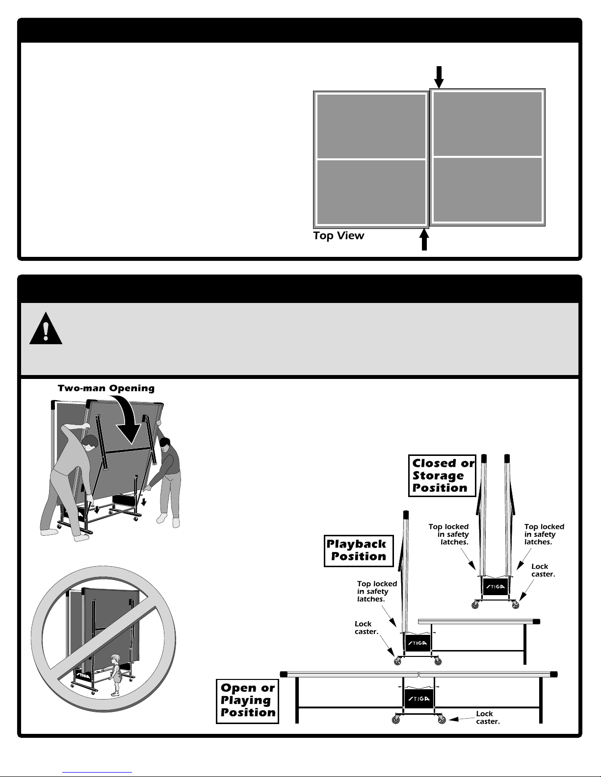
If sides of table are not even with one
another, loosen the bottom four bolts that
were loosened in the previous page and push
both sides inward as shown until they are even.
Retighten bolts when sides are even.
FINISHING THE ASSEMBLYOPERATING INSTRUCTIONS
CAUTION
ALWAYS LOCK TABLE TOP HALVES IN SAFETY LATCHES WHEN STORING,ALWAYS LOCK TABLE TOP HALVES IN SAFETY LATCHES WHEN STORING,ALWAYS LOCK TABLE TOP HALVES IN SAFETY LATCHES WHEN STORING,ALWAYS LOCK TABLE TOP HALVES IN SAFETY LATCHES WHEN STORING,ALWAYS LOCK TABLE TOP HALVES IN SAFETY LATCHES WHEN STORING,MOVING, OR USING TABLE IN ITS PLAYBACK POSITION!MOVING, OR USING TABLE IN ITS PLAYBACK POSITION!MOVING, OR USING TABLE IN ITS PLAYBACK POSITION!MOVING, OR USING TABLE IN ITS PLAYBACK POSITION!MOVING, OR USING TABLE IN ITS PLAYBACK POSITION!!!!!! ALWAYS LOCK CASTERS, EXCEPT WHEN MOVING TABLE!ALWAYS LOCK CASTERS, EXCEPT WHEN MOVING TABLE!ALWAYS LOCK CASTERS, EXCEPT WHEN MOVING TABLE!ALWAYS LOCK CASTERS, EXCEPT WHEN MOVING TABLE!ALWAYS LOCK CASTERS, EXCEPT WHEN MOVING TABLE!!!!!! DO NOT SIT, STAND, WALK OR JUMP ON THIS TABLE!DO NOT SIT, STAND, WALK OR JUMP ON THIS TABLE!DO NOT SIT, STAND, WALK OR JUMP ON THIS TABLE!DO NOT SIT, STAND, WALK OR JUMP ON THIS TABLE!DO NOT SIT, STAND, WALK OR JUMP ON THIS TABLE!!!!!! DO NOT ALLOW CHILDREN TO PLAY ON OR NEAR TABLE! SERIOUS OR FATALDO NOT ALLOW CHILDREN TO PLAY ON OR NEAR TABLE! SERIOUS OR FATALDO NOT ALLOW CHILDREN TO PLAY ON OR NEAR TABLE! SERIOUS OR FATALDO NOT ALLOW CHILDREN TO PLAY ON OR NEAR TABLE! SERIOUS OR FATALDO NOT ALLOW CHILDREN TO PLAY ON OR NEAR TABLE! SERIOUS OR FATALINJURY COULD RESULT.INJURY COULD RESULT.INJURY COULD RESULT.INJURY COULD RESULT.INJURY COULD RESULT.To open table:To open table:To open table:To open table:To open table:1.1.1.1.1.Lock both locking casters.2.2.2.2.2.With the aid of another adult, hold table halfwith one hand and release safety latches(both at the same time).3.3.3.3.3.Open table half slightly, until free of safetylatches.4.With both hands on table half, lower table tophalf.5.Repeat on other half.To close table:To close table:To close table:To close table:To close table:1.1.1.1.1.Be sure both locking casters are locked.2.2.2.2.2.Lift table top half until edge of table half lockssecurely in safety latches.DO NOT ALLOWDO NOT ALLOWDO NOT ALLOWDO NOT ALLOWDO NOT ALLOWCHILDREN TO PLAYCHILDREN TO PLAYCHILDREN TO PLAYCHILDREN TO PLAYCHILDREN TO PLAYON OR AROUNDON OR AROUNDON OR AROUNDON OR AROUNDON OR AROUNDTABLE! SERIOUS ORTABLE! SERIOUS ORTABLE! SERIOUS ORTABLE! SERIOUS ORTABLE! SERIOUS ORCOULD RESULT!COULD RESULT!COULD RESULT!COULD RESULT!COULD RESULT!8
FATAL INJURY
!!Downloaded from www.Manualslib.com manuals search engine

ONE YEAR LIMITED WARRANTYThis consumer warranty extends to the original consumer purchase of any ESCALADE® SPORTS Product(hereinafter referred as the "Product").WARRANTY DURATION: This Product is warranted to the original consumer purchase of a period of one (1) year from the originalpurchase.WARRANTY COVERAGE:ESCALADE SPORTS warrants to the original Consumer Purchaser that any Product of its manufacture is free fromdefects in material and workmanship when used for the intended purpose under normal use and conditions. THIS WARRANTY IS VOID IF THEPRODUCT HAS BEEN DAMAGED BY ACCIDENT, UNREASONABLE USE, NEGLIGENCE, IMPROPER SERVICE, FAILURE TO FOLLOW IN-STRUCTIONS PROVIDED WITH THE PRODUCT OR OTHER CAUSES NOT ARISING OUT OF DEFECTS IN MATERIAL AND WORK-MANSHIP.WARRANTY PERFORMANCE:During the above one (1) year warranty period, ESCALADE SPORTS shall repair or replace with acomparable model, and Product, or component thereof, which may prove defective under normal use and proper care, and which ourexamination shall disclose to our satisfaction to be thus defective, please contact our Warranty Dept.arranty Dept.Or Write us at:Escalade® Sports, Inc. - P.O. Box 889, Evansville, IN 47706 - Attn: Warranty Dept.Or E-mail us at:customerservice@escaladesports.comOther than shipping requirements no charge will be made for such repair or replacement of in-warranty Products. ESCALADE® SPORTSstrongly recommends that the Product is insured for value prior to mailing.WARRANTY DISCLAIMERS: ANY IMPLIED WARRANTIES ARISING OUT OF THIS SALE, INCLUDING BUT NOT LIMITED TO THEIMPLIED WARRANTIES OF MERCHANTABILITY AND FITNESS FOR A PARTICULAR PURPOSE, ARE LIMITED IN DURATION TO THEABOVE ONE (1) YEAR WARRANTY PERIOD. ESCALADE® SPORTS SHALL NOT BE LIABLE FOR LOSS OF USE OF THE PRODUCT OROTHER CONSEQUENTIAL OR INCIDENTAL COSTS, EXPENSES OR DAMAGES INCURRED BY THE CONSUMER OF ANY OTHER USE.Some states do not allow the exclusion or limitation of implied warranties or consequential or incidental damages, so the abovelimitations or exclusions may not apply to you.LEGAL REMEDIES: This warranty gives you specific legal rights and you may also have other rights which may vary from state to state.CARE AND MAINTENANCEYou have purchased a quality product that will give you years of enjoyment. By following these simple maintenance steps, you will add to the life of your new table.THE TABLE TOPThe top (playing surface) of your table is made of particle board or MDF. Like all products made of wood, it can be affected by atmospheric changes in both temperature and humidity. This may cause a slight sag or distortion as the top expands or contracts. This is normal and should not cause concern as it does not detract from the play or utility value of the table. After assembly of the table, you can minimize the effects of temperature and humidity changes by storing the table in the folded up position in a dry area when table is not in use.STORAGE OF YOUR TABLEThis table must be stored indoors to prevent damage to the playing surface. Dampness and extreme temperature changes can cause the wood to warp, swell, crack or blister. When your table is not in use, it should be folded up in a dry area. Due to the nature of particle board, table top may bow. Damp and humid conditions will amplify this. This is normal and will not affect playability of table.CLEANING YOUR TABLETo clean your table use a soft, damp (NOT WET) cloth only. To prevent damage to your table's playing surface, DO NOT USE ANY CHEMICALS, ABRASIVE OR CLEANING PRODUCTS on your table's playing surface.MAINTENANCE OF YOUR TABLEBe sure to oil all moving parts of your table including the pivot points. This will insure the safety and ease of use of your table.This table must be kept indoors to prevent damage to the playing surface. Dampness and extreme temperature changes which occur on patios or similar areas can cause wood to warp, swell, crack or blister.UNLEVEL FLOORSIf table does not seem level, it is probably due to uneven or unlevel floors. Set the table in its PLAYING POSITION and move table several inches in different directions to find the best location for the table then use leg levelers provided to level table. If the floor is extremely unlevel, table may not play or operate properly.1-866-873-3528 / W9Downloaded from www.Manualslib.com manuals search engine

T8525 PARTS LISTUse PART # columnwhen calling forreplacement parts.QTY. column refers tothe total number ofpieces in product.ITEM # PART# DESCRIPTION QTY.ITEM # PART# DESCRIPTIONQTY12345678910111213141516174A-6324-012S-4668-022S-4668-032S-5136-023M-4167-002S-6139-011B-4082-994A-6161-082Q-6467-001A-4128-011A-4130-018S-6503-022Q-4025-012Q-4026-013M-6248-002L-4140-042B-4043-02Table Top HalfSide Rail - Right HandSide Rail - Left HandBall Holder End RailCorner ProtectorMounting Bracket#8 x 9/16 ScrewName PanelLeg Leveler M12Leg AssemblyUpright AssemblyCaster BeamCaster (Non-locking)Caster (Locking)Tube PlugOwner's Manual3/8 Push Nut2222481342222222414181920212223242526272829303132337B-4059-027B-6240-037B-4046-023M-4143-001B-4159-022B-5045-008S-6504-031B-6047-02WB-1110-021B-5012-022B-4047-021B-6477-023M-4150-003M-4151-005A-4276-002B-6284-00Nylon SpacerSpacer BushingSpacerLock Lever Cap¼ -20 x 4 Hex Head Bolt3/8 Heavy WasherLinkage5/16-18 x 3 Hex Head Bolt¼ -20 x 2 Hex Head Bolt¼ -20 x 3 Hex Head Bolt¼ -20 Locknut¼ -20 x 3-1/4 Hex Head BoltRH Rail End CapLH Rail End CapNet and Post SetHex Nut M12848444448420422142L-4140-0410
282817141327
18
15122319252882026453612129282028221810273031779
33(Nut)
2424118
This manual suits for next models
1
Table of contents
Other Stiga Accessories manuals

Stiga
Stiga RIM 45 CM Installation guide

Stiga
Stiga GOAL SCORER Installation guide

Stiga
Stiga Jr User manual

Stiga
Stiga 79-2500-01 User manual

Stiga
Stiga SensorScore T1830 User manual

Stiga
Stiga 78-1000 Series User manual

Stiga
Stiga GUARD 61-4820-34 Installation guide

Stiga
Stiga King Size GT User manual

Stiga
Stiga GOAL PRO Installation guide

Stiga
Stiga SNOW RACER User manual