Maintenance Guide HPC 3 / 17
Similarly, the Manufacturer shall report faults discovered on the machines produced, with
recommendations for the most suitable procedures to remediate the same.
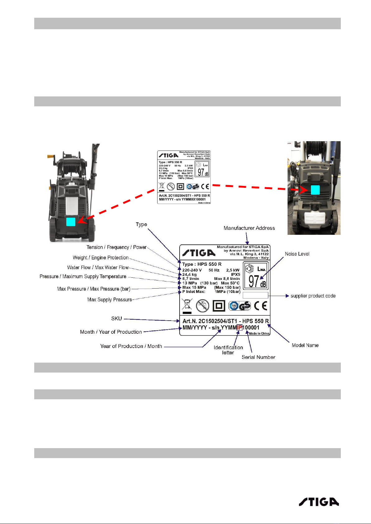
2.5 Spare parts request
When requesting spare parts, the code number must be given, referring to the exploded charts for
the year of manufacture, shown on the identification label [2.1Identification]
3. Safety regulations
General information:
This chapter covers the main aspects of a servicing procedure and the general rules for guaranteeing
a successful service, which respects the safety of the machine.
A) Qualification of operators
All maintenance, disassembly and repairs must be carried out by expert mechanics who are familiar
with all the accident prevention and safety regulations after reading through the procedures in this
manual.
B) Safety measures
All the machines are manufactured in accordance with the strict European safety regulations in force.
To maintain these levels of safety in the long term, the Service Centres should work to this end by
making appropriate checks every time there is the chance to do so.
In particular, every time work is performed on the machine, the Service Centre should:
1) check:
that the casings and protection guards have not been removed;
that the labels bearing instructions or provisions have not been removed or have become
illegible (these form an integral part of the safety system).
2) they should also:
reassemble inefficient, damaged or missing casings and protection guards;
replace illegible labels;
not endorse any repair or modification on the machine which results in a change in
performance or use that is improper or different from the purpose for which it was
designed and approved;
warn the Customer that failure to comply with the above points shall result in the
automatic cancellation of the Warranty whereby the Manufacturer is relieved from all
and any responsibility.
C) Precautions during servicing
The operations described in this manual do not entail particularly hazardous situations besides the
normal hazard relatedto mechanical operations and that can be avoided by taking the necessary care
and attention normally required for this type of work.
As well as following the usual accident prevention regulations that apply to most repair shops, we
recommend you:
ensure that other persons cannot accidentally carry out actions that may physically
endanger those working on the machine;
always use original spare parts and accessories;
disconnect the electrical power supply before carrying out user maintenance;
high pressure jets can be dangerous. Never direct the water jet at persons, pets, live
electrical equipment or towards the machine itself;
never try to clean clothes or footwear on yourself or other persons;
ENSURE that all people or animals are kept at a minimum distance of 16 yd. (15m).
D) Necessary equipment
All the operations can be carried out with the tools normally used in a reputable workshop