Stiga 13-6216-14 User manual

8211-0084-70
INSTRUCTIONS FOR USE
MODE D’EMPLOI
SAFETY REGULATIONS
SAFETY RULES ANSI
CONSIGNES DE SECURITE
RÈGLES DE SÉCURITÉ ANSI
EN ... 5
FR .. 12
EN...19
EN...23
FR....25
FR....29

2
A
B
S
I
FG
IHG
D, E
C
MON
P
1
3
5
2
4
6

3
U
T
Q
R
0
1
7
9
11
8
10
12

4
K L
13
15
17
14
16
18

5
ENGLISH EN
1 GENERAL
This symbol indicates WARNING.
Personal injury and/or damage to
property may result if the instructions
are not followed carefully.
You must read these instructions for use
and the accompanying pamphlet
“SAFETY INSTRUCTIONS”
carefully, before starting up the
machine.
1.1 SYMBOLS
The following symbols appear on the machine.
They are there to remind you of the care and
attention required in use.
This is what the symbols mean:
Warning!
Read the instruction manual and the safety
manual before using the machine.
Warning!
Watch out for discarded objects. Keep
onlookers away.
Warning!
Always wear hearing protectors.
Warning!
This machine is not designed to be driven
on public roads.
Warning!
The machine, equipped with original
accessories, may not be driven on slopes
greater than 10º in any direction.
Warning!
Risk of burn injuries. Do not touch the
silencer.
1.2 GENERALHD
This machine is available in two versions.
• Manual transmission, designated Man.
• Hydrostatic transmission, designated HD.
1.3 References
The figures in these instructions for use are
numbered 1, 2, 3, etc.
Components shown in the figures are marked A, B,
C, etc.
A reference to component C in figure 2 is written
“2:C”.
2 ASSEMBLY
To avoid injury and damage to people
and property, do not use the machine
until all the measures under “ASSEM-
BLY” have been carried out.
2.1 ACCESSORIES BAG
The machine is supplied with a plastic bag contain-
ing components which must be installed prior to
use. The bag contains (fig. 1):
Pos. No. Designation Dimension
A 1 Drawing plate
B 2 Screw 8 x 20
C 1 Tension pin 6 x 36
D 1 Shim washer 16 x 38 x 0.5
E 1 Shim washer 16 x 38 x 1.0
F 2 Shoulder washer
G 4 Screw 8 x 20
H 2 Screw knob
I 2 Washer 8.4 x 24 x 2.0
J 1 Spare key
K 1 Battery belt
2.2 ENGINE CASING
To fill with fuel and to inspect and maintain the en-
gine and battery, open the engine casing.
The engine must not be running when
the casing is opened.
2.2.1 Opening
1. Ensure that the control arms are in their forward
positions.
2. Raise the seat lock (2:S) and fold the seat for-
wards.
3. Grasp the front edge of the engine casing and
fold up the casing (fig. 3).
2.2.2 Closing
Grasp the front edge of the engine casing and fold
down the casing (fig. 3).
The machine may not be operated un-
less the engine casing is folded down.
Risk of burns and crushing injuries.
2.3 Battery
Position the battery (14:L) in the appropriate place
under the engine casing, secure with the battery
belt (14:K) and connect the battery cables.
See “6.8 Battery”.
The battery must be fully charged be-
fore being used for the first time. The
battery must always be stored fully
charged. If the battery is stored while
discharged, serious damage will occur.

6
ENGLISH
EN
2.4 Seat
Release the catch (2:S) and fold up the seat brack-
et.
Install the mounting in the rear (upper) holes as
follows:
1. Install the shoulder washers (2:F) on the screws
(2:G).
2. Insert the screws through the slots in the brack-
et. Place a washer (2:I) between the seat and the
bracket.
3. Tighten the screws in the seat. Tightening
torque: 9±1.7 Nm.
If the screws are tightened more than
9±1.7 Nm, the seat will be damaged.
4. Check that the seat moves easily in the slots in
the bracket.
Install the mounting in the front (lower) holes as
follows:
1. Install the screw knobs (2:H) on the screws
(2:G).
2. Install a washer (2:I) on each screw.
3. Insert the screws through the slots in the bracket
and tighten by hand in the seat.
4. Fold the seat down and place it in the desired
position.
5. Tighten the screw knobs (2:H) by hand.
The screw knobs (2:H) and the seat will
be damaged if tools are used.
The seat can be folded. If the machine is parked
outside when it is raining, fold the seat forward to
protect the seat cushion from getting wet.
The seat is locked. To fold the seat up or down, re-
lease the catch (2:S).
2.5 Steering wheel
In order to minimise the axial play in the steering
column, the shim washers (4:D) and/or (4:E) must
be installed on the steering column between the
steering column jacket and the bracket as follows.
1. Install the steering column jacket on the steer-
ing column and secure by knocking in the cotter
pin (4:C) approximately 1/3 of its length.
2. Pull the steering column jacket and the steering
column up.
3. From the outside, check whether no washers,
the 0.5 mm washer, the 1.0 mm washer or both
washers can be inserted into the gap. The wash-
er/washers must not be forced in, as there must
be a little axial play.
4. Pull out the cotter pin and dismantle the steering
wheel jacket.
5. Install the washer/washers in accordance with
point 3 above.
6. Install the steering column jacket on the steer-
ing column and secure by knocking in the cotter
pin fully. Use a counterhold.
2.6 TOWING HITCH
Screw the towing hitch (5:A) into the two holes on
the underside of the rear axle using screws 5:B).
Tighten the screws properly.
Tightening torque: 22 Nm.
2.7 TYRE PRESSURE
Check the air pressure in the tyres. Correct air
pressure:
Front: 0.4 bar (6 psi)
Rear: 1.2 bar (17 psi)
2.8 ACCESSORIES
For the installation of accessories, see separate in-
stallation guide supplied with each accessory.
Note: The cutting deck is regarded as an accessory
here.
3 CONTROLS
3.1 Implement lifter, mechanical
(6:P)
To switch between working position and transport
position:
1. Depress the pedal fully.
2. Release the pedal slowly.
3.2 SERVICE BRAKE/CLUTCH
(6:HM (Man)
A pedal that combines both service brake and
clutch. There are 3 positions:
1. Pedal released – forward drive
engaged. The machine will
move if a gear is engaged.
Service brake not activated.
2. Pedal depressed halfway –
forward drive disengaged, gear
shifting can be performed.
Service brake not activated.
3. Pedal fully depressed –
forward drive disengaged.
Service brake fully activated.
NOTE! You must never regulate the operating
speed by slipping the clutch. Use a suitable gear
instead, so that the right speed is obtained.

7
ENGLISH EN
3.3 Clutch-parking brake (6:M)
(HD)
The pedal (6:M) has the follow-
ing three positions:
•Released. The clutch is not activated. The park-
ing brake is not activated.
•Depressed halfway. Forward drive disengaged.
The parking brake is not activated.
•Pressed down. Forward drive disengaged. The
parking brake is fully activated but not locked.
•
3.4 Inhibitor, parking brake (6:N)
The inhibitor locks the (6:M) pedal in the
depressed position. This function is used
to lock the machine on slopes, during
transport, etc.
The parking brake must always be re-
leased during operation.
Locking:
1. Depress the pedal (6:M) fully.
2. Move the inhibitor (6:N) up.
3. Release the pedal (6:M).
4. Release the inhibitor (6:N).
Unlocking:
Press and release the “clutch-brake” (6:M) pedal.
3.5 Driving-service brake (6:O)
(HD)
The pedal (6:O) determines the gearing ratio be-
tween the engine and the drive wheels (= the
speed). When the pedal is released, the service
brake is activated.
1. Press the pedal forward –
the machine moves forward.
2. No load on the pedal – the ma-
chine is stationary.
3. Press the pedal backward –
the machine reverses.
4. Reduce the pressure on the
pedal – the machine brakes.
3.6 THROTTLE/CHOKE CONTROL
(7:T)
A control for setting the engine speed and to choke
the engine when starting from cold.
1. Choke – for starting a cold engine. The
choke is located in the top of the groove.
Avoid operating the machine in this
position, taking care to move the control
to full throttle (see below) when the
engine is warm.
2. Full throttle – when the machine is in
operation, full throttle should always be
used.
3. Idling.
3.7 IGNITION LOCK (7:U)
Ignition lock used for starting/stopping the engine.
Four positions:
1. Stop position – the engine is short-
circuited. The key can be removed.
2/3. Operating position.
4. Start position – the electric start motor
is activated when the key is turned to the
spring-loaded start position. Once the
engine has started, let the key return to
operating position 2/3.
3.8 GEAR LEVER (7:R) (Man)
A lever for selecting one of the five forward gears
in the gearbox (1-2-3-4-5), neutral (N) or reverse
(R).
The clutch pedal must be kept pressed in when
changing gear.
NOTE! You must make sure the machine is quite
stationary before changing from reverse to forward
gear or vice versa. If a gear does not engage
immediately, release the clutch pedal and then
press it in once again. Engage the gear once again.
Never force a gear in.
3.9 POWER TAKE-OFF (7:Q)
A lever for engaging and disengaging the power
take-off for operating the cutting deck. Two
positions:
1.Forward position – power take-off
disengaged.
2. Backward position – power take-off
engaged.

8
ENGLISH
EN
3.10CLUTCH RELEASE LEVER
(fig. 8) (HD)
A lever for disengaging the variable transmission.
Enables the machine to be moved by hand without
the help of the engine. Two positions:
1. Lever pressed in –
transmission engaged for normal
operation.
2. Lever pulled out –
transmission disengaged. The
machine can be moved by hand.
The machine may not be towed over long distances
or at high speeds. The transmission could be
damaged.
4 AREAS OF USE
The machine may only be used for the following
tasks using the genuine STIGA accessories stated.
Mowing:
With cutting deck 13-2940 (85M).
The maximum vertical load on the towing hitch
must not exceed 100 N.
The maximum over-run load on the towing hitch
from towed accessories must not exceed 500 N.
NOTE! Before using a trailer – contact your
insurance company.
NOTE! This machine is not intended to be driven
on public roads.
5 STARTING AND OPERATION
5.1 ENGINE CASING
See “2.2 ENGINE CASING”.
The machine may not be operated
unless the engine casing is folded down.
Risk of burns and crushing injuries.
5.2 FILLING THE FUEL TANK
Open the engine casing as above. Unscrew the
filler cap and fill with clean, lead-free petrol. You
must never use 2-stroke petrol mixed with oil (fig.
9).
NOTE! Bear in mind that ordinary lead-free petrol
is a perishable; do not purchase more petrol than
can be used within thirty days.
Environmental petrol can be used, i.e. alkylate
petrol. This type of petrol has a composition that is
less harmful for people and nature.
Petrol is highly inflammable. Always
store fuel in containers that are made
especially for this purpose.
Only fill or top up with petrol outdoors,
and never smoke when filling or
topping up. Fill up with fuel before
starting the engine. Never remove the
filler cap or fill with petrol while the
engine is running or still warm.
Never completely fill the petrol tank. Leave an
empty space (= at least 2-3 cm at the top of the
tank) to allow the petrol to expand when it warms
up without overflowing.
5.3 CHECKING THE ENGINE OIL
LEVEL
On delivery, the crankcase is filled with SAE 30
oil.
Check the oil level every time before using to
ensure it is correct. The machine should be
standing on level ground.
Wipe clean around the oil dipstick.
Unscrew and pull it up. Wipe off the
dipstick. Slide it down completely and
tighten it.
Then unscrew it and pull it up again. Read off the
oil level. Top up with oil to the “FULL” mark, if
the level comes below it (fig. 10).
5.4 SAFETY SYSTEM
This machine is equipped with a safety system that
consists of:
- a switch on the gearbox (only Man).
- a switch on the break pedal (only HD).
- a switch in the seat/seat bracket (all).
In order to start the machine, the following are
necessary:
- gear lever in neutral (only Man).
- brake pedal pressed down.
- driver sitting on seat.
- power take-off disengaged.
Always check the operation of the
safety system before using the machine!
With the engine running and the driver sitting on
the seat, check as follows:
- select a gear, lift your weight off the seat – the
engine must stop (only Man).
- press the drive pedal so that the machine starts
to move, release the drive pedal – the machine
should stop (only HD).
- engage the power take-off, lift your weight off
the seat – the engine should stop.
Do not use the machine if the safety
system is not working! Take the
machine to a service workshop for
inspection!

9
ENGLISH EN
5.5 STARTING ENGINE
1. Open the fuel cock (fig. 11).
2. Make sure that the spark plug cable is properly
in place.
3. Check to make sure that the power take-off is
disengaged.
4a. Man:Put the gear lever in neutral.
4b. HD: Do not keep your foot on the drive pedal.
5. Starting cold engine – put the throttle control in
the choke position. Starting warm engine – put the
throttle control at full throttle (approx. 1 cm behind
the choke position).
6. Depress the brake pedal fully.
7. Turn the ignition key and start the engine.
8. Once the engine has started, move the throttle
control gradually to full throttle if the choke has
been used.
9. When starting from cold, do not make the
machine work under load immediately, but let the
engine run for a few minutes first. This will allow
the oil to warm up.
When in use, always operate the engine at full
throttle.
5.6 STOPPING
Disengage the power take-off. Apply the parking
brake.
Allow the engine to idle 1 - 2 mins. Stop the engine
by turning off the starter key.
Shut off the petrol cock. This is particularly
important if the machine is to be transported on a
trailer for example.
If the machine is left unattended,
remove the ignition key. Also remove
the spark plug cable from the spark
plug.
The engine may be very warm
immediately after it is shut off. Do not
touch the silencer, cylinder or cooling
fins. This can cause burn injuries.
5.7 DRIVING TIPS
Make sure that there is the correct quantity of oil in
the engine when driving on slopes (oil level on
“FULL”).
Be careful when driving on slopes. No
sudden starting or stopping when
moving up or down a slope. Never drive
across a slope. Move from the top down,
and from the bottom to the top.
The machine, equipped with original
accessories, may not be driven on slopes
greater than 10º in any direction.
Reduce the speed on slopes and when
making sharp turns to prevent the
machine from tipping over or you
losing control of the machine.
Do not turn the steering wheel to full
lock when driving in top gear and at full
throttle. The machine can easily topple
over.
Keep hands and fingers well away from
the seat bracket. Risk of crushing
injuries. Never drive with the engine
casing open.
Never drive with the cutting deck in the
raised position. This damages the deck
drive belt.
6 MAINTENANCE
6.1 SERVICE PROGRAM
In order to keep the machine in good condition, as
regards reliability and operational safety as well as
from an environmental perspective, STIGA’s
service program should be followed.
We recommend that all service work is carried out
by an authorised workshop. This guarantees that
the work is performed by trained personnel and
with genuine spare parts.
6.2 PREPARATIONS
Unless otherwise stated, all service and
maintenance must be carried out on a stationary
machine when the engine is not running.
Prevent the machine from rolling by
always applying the parking brake.
Prevent unintentional starting of the
motor by disengaging the drive,
shutting off the engine and
disconnecting the spark plug cable or
removing the starter key.
6.3 CLEANING
To reduce the risk of fire, keep the
engine, silencer, battery and fuel tank
free from grass, leaves and oil.
To reduce the risk of fire, regularly
check the machine for oil and/or fuel
leakage.
When washing the machine with water under high
pressure, do not point the jet directly at the
transmission.
Do not point jets of water directly at the engine.
Use a brush or compressed air in order to clean it.

10
ENGLISH
EN
6.4 ENGINE OIL
Change engine oil the first time after 5 hours of
operation, and subsequently after every 50 hours
of operation or once a season.
Change the oil more often (after 25 hours of
operation or at least once a season) if the engine
has to operate under demanding conditions or if
the ambient temperature is high.
Change oil when the engine is warm. Always use
a good grade of synthetic oil (service grade SF, SG
or SH).
The engine oil may be very hot if it is
drained off directly after the engine is
shut off. So allow the engine to cool a
few minutes before draining the oil.
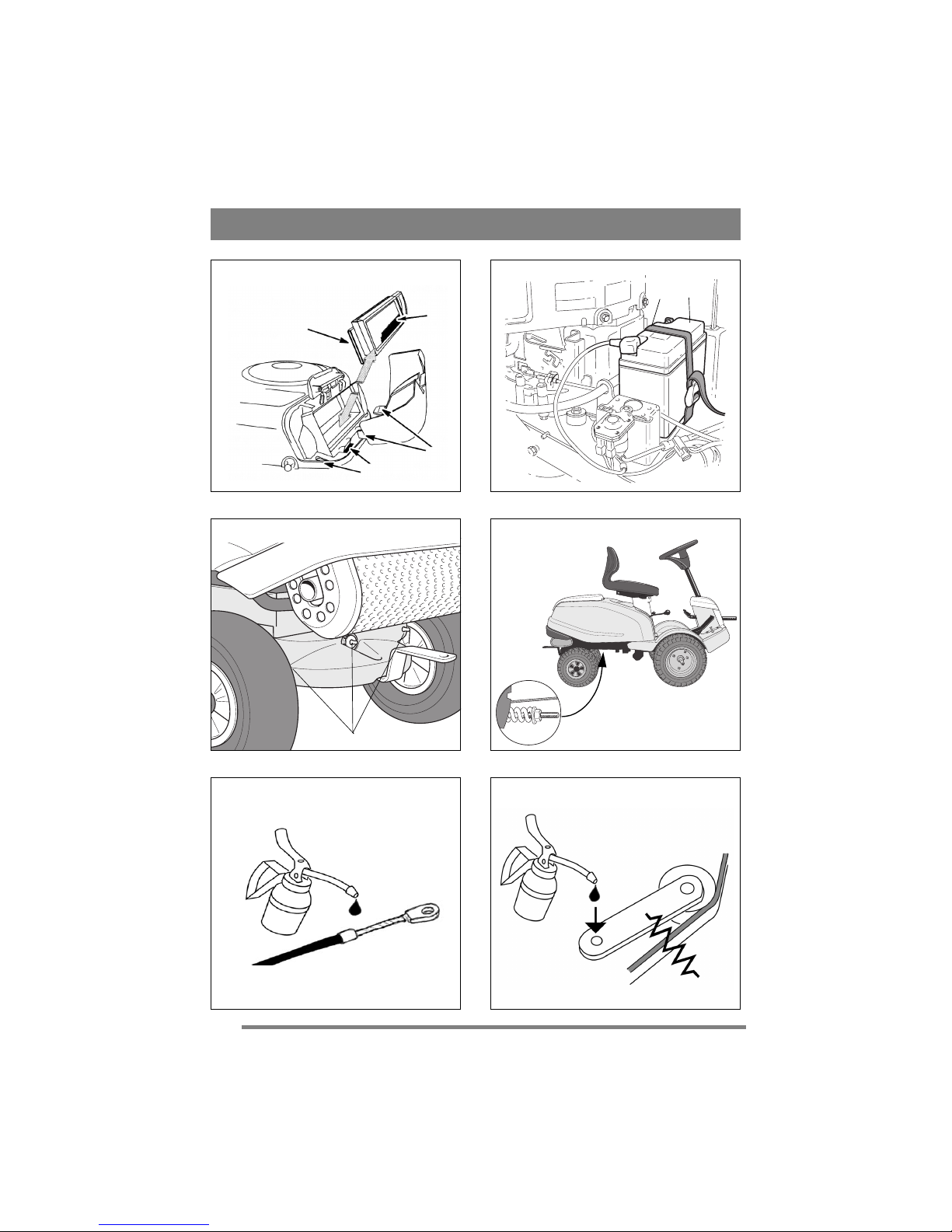
Unscrew the oil drain plug (fig. 12). It is situated
on the left of the engine (machine viewed from the
rear).
Collect the oil in a collection vessel. Then take
the oil to a recycling station. Do not allow oil to
get on the V-belts.
Screw in the oil drain plug.
Remove the dipstick and fill up with new oil to the
“FULL” mark.
Oil capacity: 1.4 litres
Oil type, summer (> 4ºC): SAE-30
(SAE 10W-30 can also be used. However, oil
consumption may increase somewhat if 10W-30 is
used. Therefore, check the oil level more regularly
if you use this type of oil).
Oil type, winter (< 4ºC): SAE 5W-30
(if this oil is not available, use SAE 10W-30).
Use oil without any additives.
Do not fill with too much oil. This can cause the
engine to overheat.
6.5 AIR FILTER - ENGINE
Change the pre-filter once a year or every 25 hours
of operation.
Clean the paper filter insert once a year or after
every 100 hours of operation, whichever comes
first.
NOTE! Both filters should be replaced/cleaned
more often if the machine operates on dusty
ground.
1. Remove the protective cover on the air filter
(fig. 13).
2. Dismantle the paper filter insert and the foam
pre-filter. Make sure that no dirt gets into the
carburettor. Clean the air filter housing.
3. Replace the pre-filter.
4. Clean the paper filter insert as follows: Knock it
lightly against a flat surface. If the filter is very
dirty, change it.
5. Assemble in the reverse order.
Petroleum-based solvents such as kerosene may
not be used for cleaning the paper filter insert.
These solvents can destroy the filter.
Do not use compressed air for cleaning the paper
filter insert. The paper filter insert must not be
oiled.
6.6 SPARK PLUG
Clean the spark plug after every 100 hours of
operation or once a season.
The engine manufacturer recommends:
Champion RC12YC.
Correct spark gap: 0.7 - 0.8 mm.
6.7 COOLING AIR INTAKE - ENGINE
The engine is air-cooled. A blocked cooling
system can damage the engine. The engine should
be cleaned at least once a year or every 100 hours
of operation.
Remove the fan casing. Clean the cooling fins on
the cylinder, the fan and the rotating protective
grille. Clean more frequently if mowing dry grass.
6.8 Battery
Do not short circuit the battery’s termi-
nals. Sparks occur which can result in
fire. Do not wear metal jewellery which
can come into contact with the battery
terminals.
In the event of damage to the battery
casing, cover, terminals or damage to
the strip covering the valves, the bat-
tery should be replaced.
The battery is a valve-regulated battery with 12 V
nominal voltage. The battery fluid does not need to
and cannot be checked or topped up. The only
maintenance that is required is charging, for exam-
ple after extended storage.
After charging the battery must be stored in a cool
place.
The battery must be fully charged be-
fore being used for the first time. The
battery must always be stored fully
charged. If the battery is stored while
discharged, serious damage will occur.
6.8.1 Charging with the engine
The battery can be charged using the engine’s gen-
erator as follows:
1. Install the battery in the machine as shown be-
low.
2. Place the machine outdoors or install an extrac-
tion device for the exhaust fumes.
3. Start the engine according to the instructions in
the user guide.

11
ENGLISH EN
4. Allow the engine to run continuously for 45
minutes.
5. Stop the engine. The battery will now be fully
charged.
6.8.2 Charging using battery charger
When charging using a battery charger, a battery
charger with constant voltage must be used.
Contact your dealer to purchase a battery charger
with constant voltage.
The battery can be damaged if a standard type
battery charger is used.
6.8.3 Removal/Installation
The battery is placed under the engine casing. Dur-
ing removal/installation, the following applies re-
garding connection of the cables:
• During removal. First disconnect the black ca-
ble from the battery’s negative terminal (-).
Then disconnect the red cable from the battery’s
positive terminal (-).
• During installation. First connect the red cable
to the battery’s positive terminal (+). Then con-
nect the black cable to the battery’s negative ter-
minal (-).
If the cables are disconnected/connect-
ed in the wrong order, there is a risk of
a short-circuit and damage to the bat-
tery.
If the cables are interchanged, the gen-
erator and the battery will be damaged.
The engine must never be driven with
the battery disconnected. There is a risk
of serious damage to the generator and
the electrical system.
6.8.4 Cleaning
If the battery terminals are coated with oxide, they
should be cleaned. Clean the battery terminals with
a wire brush and grease them.
6.9 LUBRICATION - CHASSIS
The machine has three grease nipples on the rear
axle which are lubricated with universal grease
every 25 hours of operation
(fig. 15).
Apply universal grease to all the plastic bearings a
couple of times per season.
Apply universal grease to the control arm joints a
couple of times each season (fig. 18).
Apply a coating of engine oil to the tension arm
joints a couple of times each season.
Apply a few drops of engine oil to both ends of the
throttle control cables a couple of times a season
(fig. 17).
HD:
The hydrostatic transmission is filled with oil
(10W-40) on delivery from the factory. Unless it is
opened (only to be performed by a specialist), and
provided no leakage occurs, no topping up with oil
should normally be carried out. Transmission oil
does not normally need to be changed.
6.10STEERING CABLE
The steering cables should be adjusted for the first
time after the machine has been in operation for 2
- 3 hours, and then after every 25 hours of
operation.
Tension the steering cables by tightening up the
nut (fig. 16). Important! The screws in the ends of
the cable should be held firmly during adjustment
so that the cable is not twisted. Using an adjustable
wrench or similar, grasp the key handle on the
screws in the ends of the cable.
Adjust the steering cables until all play is removed.
Do not tension the steering cables too hard.
Otherwise the steering will be heavy and wear and
tear on the cables will increase.
7 PATENT - DESIGN
REGISTRATION
This machine or parts thereof is covered by the
following patent and design registration:
9901091-0 (SE), 9901730-3 (SE)
00921248.1 (EPC), 00931809.8 (EPC)
Manufacturer reserves the right to make
alterations to the product without prior
notification.

12
FRANÇAIS
FR
1 GÉNÉRALITÉS
Ce symbole est un AVERTISSEMENT.
Risque de blessure ou de dégât matériel
en cas de non-respect des instructions.
Avant de démarrer la machine, lire
attentivement les instructions ainsi que
les consignes contenues dans le fascicule
« RÈGLES DE SÉCURITÉ » ci-joint.
1.1 SYMBOLES
Les symboles suivants figurent sur la machine. Ils
attirent votre attention sur les dangers d’utilisation
et les mesures à respecter.
Explication des symboles :
Attention!
Lire le mode d’emploi et le manuel de
sécurité avant d’utiliser la machine.
Attention!
Attention aux projections. Travailler à une
distance suffisante de toute présence.
Attention !
Porter des protections auditives.
Attention !
Cet engin n’est pas conçu pour circuler sur
la voie publique.
Attention !
La machine, équipée d’accessoires
d’origine, ne peut en aucun cas être
utilisée sur des pentes dont l’inclinaison
est supérieure à 10°.
Attention !
Risque de brûlure. Ne pas toucher le
silencieux.
1.2 Généralités
La machine est disponible en deux versions.
• Transmission manuelle, appelée Man.
• THDransmission hydrostatique, appelée HD.
1.3 Références
Dans les instructions qui suivent, les figures sont
numérotées 1, 2, 3, etc.
Les composants illustrés sont indiqués par A, B, C,
etc.
Une référence renvoyant à l’élément C de la figure
2 sera indiqué « 2:C ».
2 ASSEMBLAGE
Pour éviter les risques de blessures ou
de dégâts matériels, ne pas utiliser la
machine avant d’avoir exécuté toutes
les instructions reprises dans lechapitre
« ASSEMBLAGE ».
2.1 ACCESSOIRES
La machine est livrée avec un sac en plastique qui
contient des éléments à installer avant la première
utilisation. Le sac contient (fig. 1) :
Pos. N° Désignation Dimensions
A 1 Plaque d’accouplement
B 2 Vis 8 x 20
C 1 Goupille de tension 6 x 36
D 1 Rondelle de réglage 16 x 38 x 0,5
E 1 Rondelle de réglage 16 x 38 x 1,0
F 2 Rondelle de butée
G 4 Vis 8 x 20
H2 Papillon
I 2 Rondelle 8,4 x 24 x 2,0
J 1 Clé supplémentaire
K 1 Sangle de batterie
2.2 CARTER DE MOTEUR
Pour faire le plein de carburant et procéder à
l’inspection et à l’entretien du moteur et de la
batterie, ouvrir le carter de moteur.
Le moteur doit être coupé pour ouvrir
le carter.
2.2.1 Ouverture
1. Vérifier que les bras sont orientés vers l’avant.
2. Rabattre le siège vers l’avant en levant le dispo-
sitif de verrouillage (2:S).
3. Saisir l’avant du carter moteur et le soulever
(fig. 3).
2.2.2 Fermeture
Saisir l’avant du carter moteur et le refermer (fig.
3).
Ne pas utiliser la machine si le carter de
moteur n’est pas fermé. Risque de brû-
lure et de blessure par écrasement.
2.3 Batterie
Mettre la batterie (14:L) en place sous le carter du
moteur, l’attacher au moyen de la sangle (14:K) et
connecter les cosses.
Voir “6.8 BATTERIE”.
Charger complètement la batterie
avant la première utilisation. La batte-
rie doit être chargée au maximum lors-
qu’on l’entrepose. Une batterie remisée
totalement déchargée risque d’être sé-
rieusement endommagée.

13
FRANÇAIS FR
2.4 Siège
Relâcher la sécurité (2:S) et replier le support du
siège.
Visser le support par les orifices arrière
(supérieurs), comme suit :
1. Mettre les rondelles (2:F) sur les vis (2:G).
2. Guider les vis par les encoches du support. Pla-
cer une rondelle (2:I) entre le siège et le support.
3. Serrer les vis dans le siège. Couple de serrage :
9±1,7 Nm.
Serrer davantage les vis endommagera
le siège.
4. Vérifier que le siège coulisse facilement dans
les encoches du support.
Visser le support par les orifices arrière
(inférieurs), comme suit :
1. Placer les papillons (2:H) sur les vis (2:G).
2. Placer une rondelle (2:I) sur chaque vis.
3. Guider les vis par les encoches du support et les
engager à la main.
4. Rabattre le siège et le placer dans la position
souhaitée.
5. Serrer les papillons (2:H) à la main.
Ne pas utiliser d’outils sous peine d’en-
dommager les papillons (2:H) et le siè-
ge.
Le siège est rabattable. Si la machine reste à
l’extérieur sous la pluie, rabattre le siège pour
éviter de mouiller les coussins.
Le siège possède un dispositif de verrouillage.
Pour le replier, tirer la sécurité (2:S) vers le haut.
2.5 Volant
Placer les rondelles de réglage (4:D) et/ou (4:E)
entre la partie inférieure de la colonne de direction
et le support comme suit pour minimiser le jeu
latéral.
1. Monter le support sur la colonne ; le fixer enga-
geant la goupille (4:C) sur environ le tiers de sa
longueur.
2. Lever l’ensemble support/colonne.
3. De l’extérieur, vérifier si vous pouvez placer,
entre les pièces, les deux rondelles, celle de 1
mm, celle de 0,5 mm ou aucune. Ne pas forcer ;
un jeu axial limité est nécessaire.
4. Retirer la goupille et démonter la partie infé-
rieure de la colonne.
5. Monter la ou les rondelles comme décrit au
point 3 ci-dessus.
6. Remonter le support sur la colonne ; le fixer en
engageant la goupille à fond. Utiliser une clé.
2.6 BARRE D’ATTELAGE
Visser la barre d’attelage (5:A) au moyen des vis
(5:B) dans les deux trous situés sous l’essieu
arrière. Serrer fermement les vis.
Couple de serrage : 22 Nm.
2.7 PRESSION DES PNEUS
Vérifier la pression des pneus. Pressions correctes
:
À l’avant : 0,4 bar (6 psi).
À l’arrière : 1,2 bar (17 psi)
2.8 ACCESSOIRES
Pour le montage des accessoires, voir le manuel
d’installation fourni séparément avec chaque
élément.
Remarque : le plateau de coupe est considéré ici
comme un accessoire.
3 RÉGLAGES
3.1 Dispositif de levage, mécanique
(6:P)
Pour passer de la position de travail à la position de
transport :
1. Enfoncer à fond la pédale.
2. Relâcher la pédale progressivement.
3.2 Frein de service/embrayage
(6:M) (Man)
Le frein de service et l’embrayage sont actionnés
par une seule pédale. Trois positions sont possibles
1. Pédale relâchée – marche
avant enclenchée. La machine
avance si une vitesse est
engagée. Le frein de service
n’est pas activé.
2. Pédale enfoncée à mi-course –
la marche avant est
désenclenchée, on peut changer
de vitesse. Le frein de service
n’est pas activé.
3. Pédale enfoncée à fond –
marche avant désenclenchée. Le
frein de service est totalement
activé.
REMARQUE ! Ne pas faire patiner l’embrayage
pour régler la vitesse de service. Il est préférable de
sélectionner un rapport adéquat pour atteindre la
vitesse souhaitée.

14
FRANÇAIS
FR
3.3 Embrayage - frein de station-ne-
ment (6:M) (HD)
La pédale (6:M) se règle sur
trois positions :
•Relâchée. L'embrayage n'est pas activé. Le
frein de stationnement n'est pas activé.
•Enfoncée à moitié. La marche avant est désac-
tivée. Le frein de stationnement n'est pas activé.
•Enfoncée . La marche avant est désactivée. Le
frein de stationnement est tout à fait activé mais
n'est pas verrouillé.
3.4 Inhibiteur, frein de stationne-
ment (6:N)
L'inhibiteur bloque la pédale (6:M) en
position enfoncée. Cette fonction permet
de circuler sur des terrains en pente, de
transporter la machine, etc.
Le frein de stationnement doit toujours
être relâché pendant l'utilisation de
l'engin.
Verrouillage :
1. Enfoncer à fond la pédale (6:M).
2. Déplacer l’inhibiteur vers le haut (6:N).
3. Relâcher la pédale (6:M).
4. Relâcher l'inhibiteur (6:N).
Déverrouillage :
Enfoncer et relâcher la pédale (6:M).
3.5 Conduite - frein de service
(6:O) (HD)
La pédale (6:O) détermine le rapport de
transmission entre le moteur et les roues motrices
(= vitesse). Le frein de service est activé lorsque la
pédale est relâchée.
1. Pédale enfoncée vers l'avant –
la machine avance.
2. Pas de pression sur la pédale –
la machine reste immobile.
3. Pédale enfoncée vers
l'arrière– la machine recule.
4. Pression réduite sur la pédale
– la machine freine.
3.6 PLEIN RÉGIME/CHOKE (7:T)
Réglage du régime moteur, permettant d’enrichir
le mélange pour le démarrage à froid
1. Choke – pour les démarrages à froid. Le
choke est situé dans la partie supérieure de
la rainure. Éviter d’utiliser la machine
dans cette position. Veiller à passer en
mode plein régime (voir ci-dessous)
lorsque le moteur est chaud.
2. Plein régime – le mode plein régime
doit toujours être enclenché lorsque la
machine fonctionne.
3. Ralenti.
3.7 BLOCAGE DE L’ALLUMAGE
(7:U)
Le contact permet de démarrer et d’arrêter le
moteur. Quatre positions :
1. Arrêt – le moteur est court-circuité. La
clé peut être retirée.
2/3. Position de conduite.
4. Démarrage – le démarreur électrique est
activé lorsque la clé est tournée à fond
dans la position de démarrage. Lorsque le
moteur tourne, laisser revenir clé en
position de marche 2/3.
3.8 LEVIER DE VITESSES (7:R)
(Man)
Levier permettant d’enclencher l’une des cinq
vitesses en marche avant (1-2-3-4-5), le point mort
(N) ou la marche arrière (R).
L’embrayage doit être maintenu enfoncé pendant
le changement de vitesse.
REMARQUE ! Veiller à ce que la machine soit à
l’arrêt complet pour passer de marche avant en
marche arrière et vice versa. Si une vitesse ne
s’enclenche pas immédiatement, relâcher
l’embrayage et l’enfoncer à nouveau. Ré-
enclencher la vitesse. Ne jamais forcer le passage
des vitesses.
3.9 PRISE DE FORCE (7:Q)
Levier permettant d’enclencher et de débloquer la
prise de force actionnant le plateau de coupe. Deux
positions sont possibles :
1.Levier vers l’avant – prise de force
désengagée.
2. Levier vers l’arrière – prise de force
engagée.

15
FRANÇAIS FR
3.10LEVIER DE DÉBRAYAGE
(fig. 8) (HD)
Levier permettant de débrayer la transmission
variable, ce qui permet de bouger la machine à la
main, moteur éteint. Deux positions sont possibles
:
1. Levier enfoncé – la
transmission est activée pour un
fonctionnement normal.
2. Levier tiré – débrayage de la
transmission. La machine peut
être déplacée manuellement.
Ne pas remorquer la machine sur
de longues distances ou à des vitesses élevées pour
éviter d’endommager la transmission.
4 UTILISATION
L’usage de la machine est réservé aux travaux
suivants, avec les accessoires STIGA d’origine
renseignés.
Tonte :
Avec plateau de coupe 13-2940 (85M).
La charge verticale maximum exercée sur la boule
de remorquage doit être inférieure à 100 N.
La charge d’inertie maximum exercée sur la boule
de remorquage par les accessoires tractés doit être
inférieure à 500 N.
REMARQUE ! Avant d’utiliser un tracteur,
contactez votre compagnie d’assurance.
REMARQUE ! Cette machine n’est pas conçue
pour circuler sur la voie publique.
5 DÉMARRAGE ET
FONCTIONNEMENT
5.1 CARTER DE MOTEUR
Voir “2.2 CARTER DE MOTEUR”.
Ne pas utiliser la machine si le carter de
moteur n’est pas fermé. Risque de
brûlure et de blessure par écrasement.
5.2 REMPLISSAGE DU RÉSERVOIR
DE CARBURANT
Ouvrir le carter moteur comme décrit ci-dessus.
Dévisser le bouchon du réservoir et remplir
d’essence sans plomb neuve. Ne jamais utiliser de
mélange carburant-huile 2 temps (fig. 9).
REMARQUE ! L’essence sans plomb ne se
conserve pas indéfiniment. Ne pas l’utiliser au-
delà de trente jours après l’achat.
Des carburants respectueux de l’environnement,
par ex. l’essence alkylate, peuvent également être
utilisés. Par leur composition, ils ont un impact
réduit sur la nature et la santé.
L’essence est très inflammable et doit
être conservée dans des récipients
spécialement conçus à cet effet.
Faire le plein d’essence uniquement à
l’extérieur, et ne pas fumer pendant
l’opération. Faire le plein de carburant
avant de démarrer le moteur. Ne jamais
enlever le bouchon du réservoir ou
procéder au remplissage quand le
moteur tourne ou est encore chaud.
Ne pas remplir le réservoir à ras bord. Laisser un
espace (= au moins 2 à 3 cm par rapport au-dessus
du réservoir) pour que le carburant puisse se dilater
sans déborder lorsqu’il se réchauffe.
5.3 NIVEAU D’HUILE MOTEUR
À la livraison, le carter est rempli d’huile SAE 30.
Vérifier le niveau d’huile avant chaque
utilisation. Placer la machine sur un sol plat.
Nettoyer la zone autour de la jauge
d’huile. La dévisser et la sortir du carter.
Essuyer la jauge au moyen d’un chiffon,
Réintroduire la jauge dans le carter et la
visser à fond.
Dévisser la jauge et la ressortir. Lire le niveau
d’huile sur la jauge. Si le niveau d’huile descend
en dessous du repère « FULL », faire l’appoint
(fig. 10).
5.4 DISPOSITIFS DE SÉCURITÉ
La machine est équipée des dispositifs de sécurité
suivants :
- un disjoncteur sur la boîte de vitesse
(uniquement Man).
- un disjoncteur sur la pédale de frein
(uniquement HD).
- un interrupteur dans le siège/support du siège
(tous les modèles).
Pour démarrer la machine, vérifier que les points
suivants sont respectés :
- mettre le levier de vitesses au point mort
(uniquement Man).
- enfoncer la pédale de frein.
- le conducteur doit être assis sur le siège.
- Prise de force désactivée.
Vérifier le bon fonctionnement des
dispositifs de sécurité avant toute
utilisation de la machine!
Lorsque le moteur tourne et que le conducteur est
assis sur le siège, procéder aux vérifications
suivantes :
- enclencher une vitesse, et se lever du siège – le
moteur doit s’arrêter (modèle Man).
- enfoncer la pédale d’accélération pour mettre la
machine en mouvement, puis la relâcher – la
machine doit s’arrêter (uniquement HD).
- enclencher la prise de force et se lever du siège
– le moteur doit s’arrêter.

16
FRANÇAIS
FR
Ne pas utiliser une machine dont les
dispositifs de sécurité sont déficients !
Faire contrôler la machine dans un
atelier agréé !
5.5 DÉMARRAGE DU MOTEUR
1. Ouvrir le robinet de carburant (fig. 11).
2. Vérifier que le câble de la bougie d’allumage est
bien branché.
3. Vérifier que la prise de force n’est pas activée.
4a. Man:Mettre le levier de vitesse en position
neutre.
4b. HD: Ne pas laisser le pied sur l’accélérateur.
5. Démarrage à froid – mettre le réglage du régime
en position choke. Démarrage à chaud – mettre la
manette sur plein régime (environ 1 cm plus loin
que la position choke).
6. Enfoncer à fond la pédale de frein.
7. Démarrer le moteur en tournant la clé de contact.
8. Lorsque le moteur a été démarré en utilisant le
choke, ramener progressivement la manette en
position de plein régime.
9. Ne pas utiliser la machine pour des travaux sous
charge immédiatement après un démarrage à froid.
Laisser d'abord tourner le moteur pendant
quelques minutes pour permettre à l’huile de
chauffer.
Le moteur doit toujours être utilisé à plein
rendement.
5.6 ARRÊT
Désactiver la prise de force. Serrer le frein de
stationnement.
Laisser tourner le moteur au ralenti pendant 1 à 2
minutes. Arrêter le moteur en tournant la clé.
Fermer le robinet de carburant. Ce point est
particulièrement important si la machine doit être
transportée par camion, par exemple.
Si la machine est abandonnée sans
surveillance, retirer la clé de contact.
Débrancher également le câble de la
bougie.
Le moteur peut être très chaud
immédiatement après l’arrêt. Ne pas
toucher le pot d’échappement, le
cylindre ni les ailettes de
refroidissement. Risque de brûlure.
5.7 CONSEILS DE CONDUITE
Pour la tonte sur terrains en pente, s’assurer que le
moteur contient suffisamment d’huile (niveau
d’huile sur « FULL »).
Être particulièrement vigilant sur les
terrains en pente. Ne pas démarrer ou
s’arrêter brutalement sur un terrain en
pente. Ne jamais circuler
perpendiculairement à une pente. Se
déplacer de haut en bas, et de bas en
haut.
La machine, équipée d’accessoires
d’origine, ne peut en aucun cas être
utilisée sur des pentes dont l’inclinaison
est supérieure à 10°.
Ralentir dans les pentes et dans les
virages pour éviter de basculer ou de
perdre le contrôle de la machine.
Ne pas braquer à fond lorsque la
machine est en vitesse supérieure et à
plein régime. Dans cette situation, elle
pourrait facilement basculer.
Garder les mains et les doigts à distance
du support du siège. Risque de blessure
par écrasement. Ne jamais utiliser la
machine lorsque le carter moteur est
ouvert.
Ne jamais rouler avec le plateau de
coupe en position levée pour ne pas
endommager sa courroie
s’entraînement.
6 ENTRETIEN
6.1 PROGRAMME D’ENTRETIEN
Respecter le programme d’entretien STIGA pour
conserver la machine en bon état de marche, qui
respecte l’environnement et reste sûre et fiable.
Il est recommandé de confier les entretiens à des
services agréés. Les travaux y seront effectués par
du personnel expérimenté n’utilisant que des
pièces d’origine.
6.2 PRÉCAUTIONS
Sauf indication contraire, les interventions et
entretiens doivent s’effectuer sur des machines
immobilisées dont le moteur est à l’arrêt.
Bloquer la tondeuse en serrant le frein à
main.
Pour éviter le démarrage intempestif
du moteur, enclencher la position
neutre, arrêter le moteur et débrancher
le câble de la borne négative de la
batterie ou retirer la clé de contact.

17
FRANÇAIS FR
6.3 NETTOYAGE
Pour réduire le risque d’incendie,
dégager l’herbe, les feuilles et
l’excédent d’huile se trouvant sur le
moteur, le pot d’échappement, la
batterie et le réservoir de carburant.
Pour réduire le risque d’incendie,
contrôler régulièrement que la machine
ne présente aucune fuite d’huile et/ou
de carburant.
En cas de nettoyage de la machine avec de
l’eau sous haute pression, ne pas diriger le jet
directement vers la transmission.
Ne pas diriger les jets d’eau directement sur le
moteur. Nettoyer le moteur à la brosse ou à l’air
comprimé.
6.4 HUILE MOTEUR
Remplacer l'huile une première fois après 5 heures
d'utilisation, puis toutes les 50 heures d'utilisation
ou une fois par saison.
Augmenter la fréquence des vidanges (toutes les
25 heures ou une fois par saison) si le moteur est
soumis à rude épreuve ou si la température
ambiante est élevée.
Vidanger l’huile quand le moteur est chaud.
Toujours utiliser de l’huile de bonne syntetic
qualité (grade SF, SG ou SH).
L’huile moteur peut être très chaude si
on l’évacue aussitôt après l’arrêt. Il est
donc recommandé de laisser refroidir le
moteur pendant quelques minutes
avant d’effectuer la vidange.
Dévisser le bouchon de vidange d’huile (fig. 12). Il
est situé sur le côté gauche du moteur (machine
vue de dos).
Récupérer l’huile dans un récipient. Déposer
ensuite l’huile usagée dans une station de
recyclage. L’huile ne peut pas entrer en contact
avec les courroies trapézoïdales.
Revisser le bouchon de vidange.
Retirer la jauge et ajouter de l’huile jusqu’à
atteindre la limite supérieure marquée « FULL ».
Contenance : 1,4 litres
Type d’huile d’été (> 4° C): SAE-30
(De l’huile SAE 10W-30 peut également être
utilisée. Toutefois, la consommation d’huile peut
augmenter légèrement avec des grades 10W-30.
Vérifier donc régulièrement le niveau d’huile en
cas d’utilisation de ces grades).
Type d’huile d’hiver (< 4° C): SAE 5W-30
(si cette huile n’est pas disponible, utiliser SAE
10W-30).
Choisir une huile sans additifs.
Ne pas trop remplir le réservoir d’huile pour éviter
la surchauffe du moteur.
6.5 FILTRE À AIR - MOTEUR
Remplacer le préfiltre une fois par an ou toutes les
25 heures d’utilisation.
Nettoyer le filtre en papier au moins une fois par an
et après un maximum de 100 heures d’utilisation.
REMARQUE ! augmenter la fréquence de
remplacement ou de nettoyage des filtres si la
machine est utilisée sur des terrains poussiéreux.
1. Retirer le couvercle du filtre à air (fig 13).
2. Démonter la partie amovible du filtre à papier
ainsi que le préfiltre en mousse. Veiller à ce
qu’aucune saleté ne tombe dans le carburateur.
Nettoyer le support du filtre à air.
3. Remplacer le préfiltre.
4. Pour nettoyer l’élément en papier du filtre,
procéder comme suit : le tapoter légèrement contre
une surface lisse. En cas d’encrassage intense,
remplacer le filtre.
5. Pour remonter le filtre, répéter les opérations
dans l’ordre inverse.
Ne pas utiliser de solvants à base de pétrole (par
ex. du kérosène) pour nettoyer le filtre en papier.
Ces solvants sont susceptibles d’endommager le
filtre.
Ne pas nettoyer à l’air comprimé l’élément en
papier du filtre. L’élément en papier ne doit pas
être huilé.
6.6 BOUGIE D’ALLUMAGE
Remplacer la bougie d’allumage après 100 heures
d’utilisation ou une fois par saison.
Recommandations du fabricant de moteur :
Champion RC12YC.
Écartement correct : 0,7 – 0,8 mm.
6.7 ENTRÉE D’AIR DE REFROIDIS-
SEMENT – MOTEUR
Le moteur est refroidi à l’air. Il peut être
endommagé en cas de défaillance du système de
refroidissement. Le moteur doit être nettoyé toutes
les 100 heures d’utilisation et au moins une fois par
an.
Retirer le carter du ventilateur. Nettoyer les ailettes
de refroidissement situées sur le cylindre, le
ventilateur et la calandre. Augmenter la fréquence
du nettoyage en cas de tonte de gazon sec.
6.8 BATTERIE
Ne pas provoquer de court-circuit aux
bornes de la batterie. Cela provoquerait
des étincelles susceptibles de mettre le
feu. Éviter également tout contact entre
les bijoux en métal et les bornes de la batterie.
Si l’extérieur, le couvercle ou les bornes de la
batterie sont endommagés ou qu’il y a de dégâts
au niveau des barrettes de connexion, rempla-
cer immédiatement la batterie.

18
FRANÇAIS
FR
La batterie est du type à soupape avec une tension
nominale de 12 V. Il ne faut pas vérifier le niveau
ou faire l’appoint de la batterie. Rien n’est
d’ailleurs prévu pour le faire. Le seul entretien
nécessaire est la charge, par exemple après un
remisage prolongé.
Après la charge, la batterie doit être stockée au
frais.
Charger complètement la batterie
avant la première utilisation. La batte-
rie doit être chargée au maximum lors-
qu’on l’entrepose. Une batterie remisée
totalement déchargée risque d’être sé-
rieusement endommagée.
6.8.1 Charge à l’aide du moteur
Pour recharger la batterie à l’aide du générateur de
la machine :
1. Placer la batterie dans la machine comme illus-
tré ci-dessous.
2. Installer la machine à l’extérieur ou raccorder
un système d’extraction d’air au pot d’échappe-
ment.
3. Suivre les instructions du manuel pour démarrer
le moteur.
4. Laisser tourner le moteur de manière ininter-
rompue pendant 45 minutes.
5. Arrêter le moteur. La batterie est à présent com-
plètement rechargée.
6.8.2 Pour recharger la batterie à l’aide
d’un chargeur
En cas d’utilisation d’un chargeur de batterie,
utiliser un modèle à tension constante
(disponible chez votre fournisseur).
L’utilisation d’un chargeur de type standard risque
d’endommager la batterie.
6.8.3 Dépose/Installation
La batterie est placée sous le carter moteur. Durant
la dépose/installation, brancher les câbles comme
suit :
• Dépose. D’abord débrancher le câble noir à la
borne négative (-). Débrancher ensuite le câble
rouge à la borne positive (-).
• Installation. D’abord brancher le câble rouge à
la borne positive (+). Brancher ensuite le câble
noir à la borne négative (-).
Un ordre incorrect de branchement/dé-
branchement peut provoquer un court-
circuit et endommager la batterie.
Intervertir les câbles endommagera la
génératrice et la batterie.
Le moteur ne peut jamais fonctionner sans
batterie raccordée. Il y a risque sérieux
d’endommager la génératrice et le
système électrique.
6.8.4 Nettoyage
Nettoyer les traces d’oxydation qui peuvent
apparaître sur les bornes. Nettoyer les bornes au
moyen d’une brosse en métal, puis les graisser.
6.9 LUBRIFICATION - CHÂSSIS
La machine possède trois points de graissage sur
l’essieu arrière. Les lubrifier à la graisse
universelle toutes les 25 heures d'utilisation
(fig. 15).
Plusieurs fois par saison, appliquer de la graisse
universelle sur les paliers en plastique.
Plusieurs fois par saison, appliquer de la graisse
universelle sur les joints des bras de commande
(fig. 18).
Plusieurs fois par saison, enduire d’huile moteur
les joints du bras oscillant.
Plusieurs fois par saison, appliquer quelques
gouttes d’huile moteur aux deux extrémités du
câble de réglage du régime (fig. 17).
HD:
À la sortie d’usine, la transmission hydrostatique
est remplie d’huile (10W-40). En principe, il ne
faut pas faire l’appoint, sauf si elle a été ouverte
(uniquement par un expert) ou si elle fuit.
Normalement, l’huile de transmission ne doit pas
être remplacée.
6.10CÂBLE DE DIRECTION
Resserrer les câbles de direction après les 2 – 3
premières heures de fonctionnement de la
machine, puis toutes les 25 heures d’utilisation.
Régler la tension des câbles de direction en serrant
l’écrou (fig. 16). Important ! Pendant le réglage,
maintenir fermement les vis aux extrémités du
câble pour éviter qu’il ne se vrille. Pour cela,
utiliser une clé à molette ou un outil similaire pour
bloquer les vis à l’extrémité des câbles.
Retendre les câbles pour supprimer tout jeu.
Ne pas appliquer une tension trop forte sur les
câbles pour éviter de durcir la direction et
d’augmenter l’usure des câbles.
7 BREVET - ENREGISTREMENT
Cette machine et les pièces qui la composent sont
enregistrées sous le n° de brevet :
9901091-0 (SE), 9901730-3 (SE)
00921248.1 (EPC), 00931809.8 (EPC)
Manufacteur se réserve le droit de modifier le
produit sans avis préalable.

19
ENGLISH GB
SAFETY INSTRUCTIONS
GENERAL
• Please read through these instructions carefully.
Learn all the controls and the correct use of the
machine.
• Before use, all drivers must apply for and
receive practical training in the operation of the
machine. Particular emphasis should be placed
on the fact that:
a. The use of ride-on lawnmowers requires care
and concentration.
b. On slopes, it is not possible to control a
sliding ride-on lawnmower by braking. The
main reasons for losing control are insufficient
traction, excessively high speed, insufficient
braking, the machine not being suited to the
task, lack of attention to the surface or incorrect
use as a towing vehicle.
• Never let children or anyone who is not familiar
with these instructions to use the machine.
Local regulations may impose restrictions as
regards the age of the driver.
• Never use the machine if others, particularly
children or animals, are in the vicinity.
• Remember that the driver is responsible for
accidents that happen to other people or their
property.
• Do not let children or other passengers to ride
with you on the machine. They might fall off
and be seriously injured, or they might prevent
the machine being driven safely.
• Do not use the machine if you are under the
influence of alcohol, drugs or medication.
Neither should you use it when you are tired or
feeling unwell.
PREPARATIONS
• Wear strong shoes and long trousers when using
the machine. Do not operate it barefoot or
wearing sandals.
• Wear appropriate clothing when using the
machine. Do not wear loose, hanging clothes,
jewellery, scarves, ties, etc., which can get
caught in rotating parts. Tie up long hair.
• Carefully check the area that is to be cut/cleared
of snow. Remove all loose stones, sticks, steel
wire and other foreign objects which the
machine could throw out.
• Warning – Petrol is highly inflammable.
a. Always store petrol in containers that are
made especially for this purpose.
b. Only fill or top up with petrol outdoors, and
never smoke when filling or topping up.
c. Fill with petrol before starting the motor.
Never remove the filler cap or fill with petrol
while the engine is running or still warm.
d. If petrol is spilt, do not try to start the engine
but instead move the machine away from the
place where the spillage occurred and avoid any
possible causes of sparks until the petrol fumes
have evaporated.
e. Do not forget to screw the cap on the petrol
tank and the storage container after filling.
• Replace faulty silencers.
• Before use, always check that blades and
mounting devices are not worn or damaged.
Replace worn or damage parts as a set so that
the correct balance is maintained.
• The battery (on electrically started machines)
gives off explosive gases. Keep sparks, flames
and cigarettes away. Ensure there is sufficient
ventilation during charging.
• The battery contains toxic material. Do not
damage the battery casing. If the casing is
damaged, avoid contact with the content of the
battery.
• Do not throw out old, defective batteries with
the rubbish. Contact the local authorities for
correct waste management.
• Do not short circuit the battery. Sparks occur
which can result in fire.
DRIVING
• Start the engine according to the instructions in
the user guide. Keep your feet away from the
blades.
• Do not run the engine in confined areas where
hazardous carbon monoxide gases can collect.
• Only use the machine in daylight or where there
is good lighting.
• Always use hearing protectors.
• Take care when approaching obstacles which
obscure your vision.
• Always keep children away from the machine’s
working area. Get another adult to keep the
children under supervision.
• Take care when reversing. Look behind you
both before and during reversing to check for
any obstacles. Look out for small children.

20
ENGLISH
GB
• Disengage the blade(s) and the connection
before starting the engine.
• Never have your hands or feet near or under
rotating parts. Watch out for the blades. Do not
stand right in front of the discharge opening.
• Avoid using the machine on wet lawns.
• Be careful when driving on slopes. No sudden
starting or stopping when moving up or down a
slope.
• Release the clutch pedal slowly. Always drive
with the gear engaged, and do not disengage
when driving down slopes.
• Never cut across a slope. Move from the top
down, and from the bottom to the top.
• Use low acceleration when engaging the drive,
especially in long grass. Reduce the speed on
slopes and when making sharp turns to prevent
the machine from tipping over or you losing
control of the machine.
• Watch out for holes in the ground and other
hidden dangers.
• Do not drive too near ditches or high edges.
The machine can turn over if a wheel drives
over the edge or the edge breaks.
• Take care when towing and when using heavy
equipment.
a. Only use an approved towing device.
b. Limit the load so that it can be controlled
safely.
c. Do not make any sudden turns. Take care
when reversing.
d. Use wheel weights or front weight when
recommended in the user instructions.
• Look out for traffic at crossings or when driving
near roads.
• Stop the blade(s) when crossing a surface other
than grass during mowing.
• When using any of the accessories, never direct
the discharge at somebody standing beside it,
and do not allow anyone to stand near the
machine when it is running.
• Never operate the machine with insufficient
protection or without the safety devices in
place.
• Existing safety devices may not be
disconnected or disengaged. Check that the
safety devices work each time before using the
machine.
• Do not alter the engine’s regulator setting and do
not race the engine. The danger of personal injury
increases when the engine is run at high revs.
• Do not touch engine components which become
warm during use. Risk of burn injuries.
• Do not leave the driving seat without:
a. Disengaging the power take-off and lowering
the accessories.
b. Putting the gear in neutral and activating the
parking brake.
c. Stopping the engine and removing the key.
• Only use accessories that are approved by the
machine’s manufacturer.
• The machine may not be used without
accessories/tools being installed in the
machine’s tool mounts. Driving without
accessories can have a negative effect on the
stability of the machine.
• Take care when using grass collectors and other
accessories. These can alter the machine’s
stability. Particularly on slopes.
• Disengage the drive to the accessories, shut off
the engine and disconnect the spark plug cable
or remove the starter key:
a. To remove sticks and rubbish or when the
discharge has become clogged.
b. To check, clean or service the machine.
c. To check whether damage has occurred and
to carry out any repairs before starting and
using the machine again after a collision with a
foreign object.
d. To check the machine if it begins to vibrate
excessively. (Check immediately).
• Disengage the drive to accessories during
transport or when the machine is not in use.
• Shut off the engine and disconnect the drive to
the accessories:
a. Before filling with petrol.
b. Before removing the grass collector.
c. Before adjusting the height setting, assuming
this cannot be done from the driver’s position.
• Reduce the acceleration when the engine is to
be stopped, and if the engine is equipped with a
fuel shut-off valve, this should be switched off
when the work is finished.
• Take care with multiple blade decks as one
rotating blade can cause other blades to rotate.
• The machine, equipped with original
accessories, must not be driven in any direction
on slopes with a gradient greater than 10º.
This manual suits for next models
1
Table of contents
Languages:
Other Stiga Tractor manuals