the design, engineering and appearance of our
products periodically.
Therefore, some changes, modifications and
improvements may not be covered in this man‐
ual.
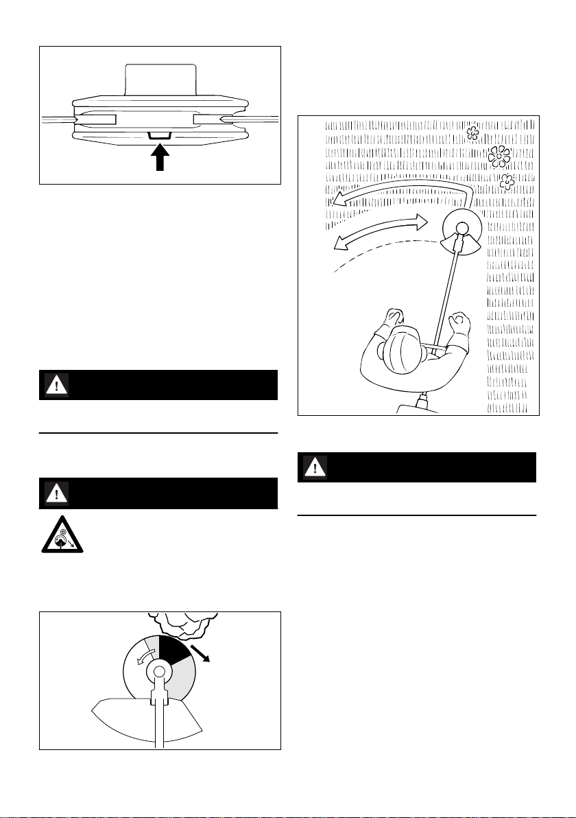
2 Safety Precautions and
Working Techniques
Because the machine is a high-speed
fast-cutting power tool, special safety
precautions must be observed to
reduce the risk of personal injury.
It is important you read and under‐
stand the User Manual before com‐
missioning and keep it in a safe place
for future reference. Non-compliance
with the User Manual may cause seri‐
ous or even fatal injury.
Observe all applicable local safety regulations,
e.g. by trade organizations, social insurance
institutions, labor safety authorities etc.
If you have never used a power tool before:
Have your dealer or other experienced user
show you how to operate your machine – or
attend a special course to learn how to operate
it.
Minors should never be allowed to use the
machine – except for apprentices over the age of
16 when working under supervision.
Children, animals and bystanders must remain at
a distance.
When not using the machine, it must be laid
down in such a way that it does not endanger
anyone. Ensure that the machine cannot be
used without authorization.
The user is responsible for accidents or risks
involving third parties or their property.
Do not lend or rent your power tool without the
User Manual. Be sure that anyone using it under‐
stands the information contained in this manual.
The use of machines that emit noise may be limi‐
ted to certain hours of the day as specified by
national and/or regional or local regulations.
Anyone operating the machine must be well res‐
ted, in good physical health and in good mental
condition.
If you have any condition that might be aggrava‐
ted by strenuous work, check with your doctor
before operating a machine.
If you have a pacemaker: The ignition system of
your machine produces an electromagnetic field
of very low intensity. This field may interfere with
some pacemakers. STIHL recommends that per‐
sons with pacemakers consult their physician
and the pacemaker manufacturer to reduce any
health risk.
Anyone who has consumed alcohol or drugs or
medicines affecting their ability to react must not
operate a power tool.
Depending on the cutting attachment fitted, use
your power tool only for cutting grass, wild
growth, shrubs, scrub, bushes, small diameter
trees and similar materials.
The machine must not be used for any other pur‐
poses – risk of accidents!
Only use cutting attachments and accessories
that are explicitly approved for this power tool
model by STIHL or are technically identical. If
you have any questions in this respect, consult
your dealer. Use only high quality parts and
accessories. in order to avoid the risk of acci‐
dents and damage to the machine.
STIHL recommends the use of original STIHL
tools and accessories. They are specifically
designed to match the product and meet your
performance requirements.
Never attempt to modify your power tool in any
way since this may increase the risk of personal
injury. STIHL excludes all liability for personal
injury and damage to property caused while
using unauthorised attachments.
The guard provided with your machine may not
protect the operator from all foreign objects
(gravel, glass, wire etc.) ejected by the revolving
cutting attachment. Ejected objects may also ric‐
ochet and strike the operator.
Do not use a high-pressure washer to clean the
power tool. The solid jet of water may damage
parts of the unit.
2.1 Clothing and equipment
Wear proper protective clothing and equipment.
Clothing must be sturdy but allow
complete freedom of movement.
Wear close-fitting clothes such as a
boiler suit, not a loose jacket.
Do not wear clothing which could become trap‐
ped in wood, brush or moving parts of the
machine. Do not wear a scarf, necktie or jewelry.
2 Safety Precautions and Working Techniques English
0458-593-8321-C 3