Contents
1 KombiSystem..............................................2
2 Guide to Using this Manual.........................2
3 Safety Precautions and Working Techni‐
ques............................................................ 2
4 Using the Unit............................................. 6
5 Approved KombiEngines............................ 7
6 Assembling the Unit.................................... 7
7 Mounting the KombiTool............................. 9
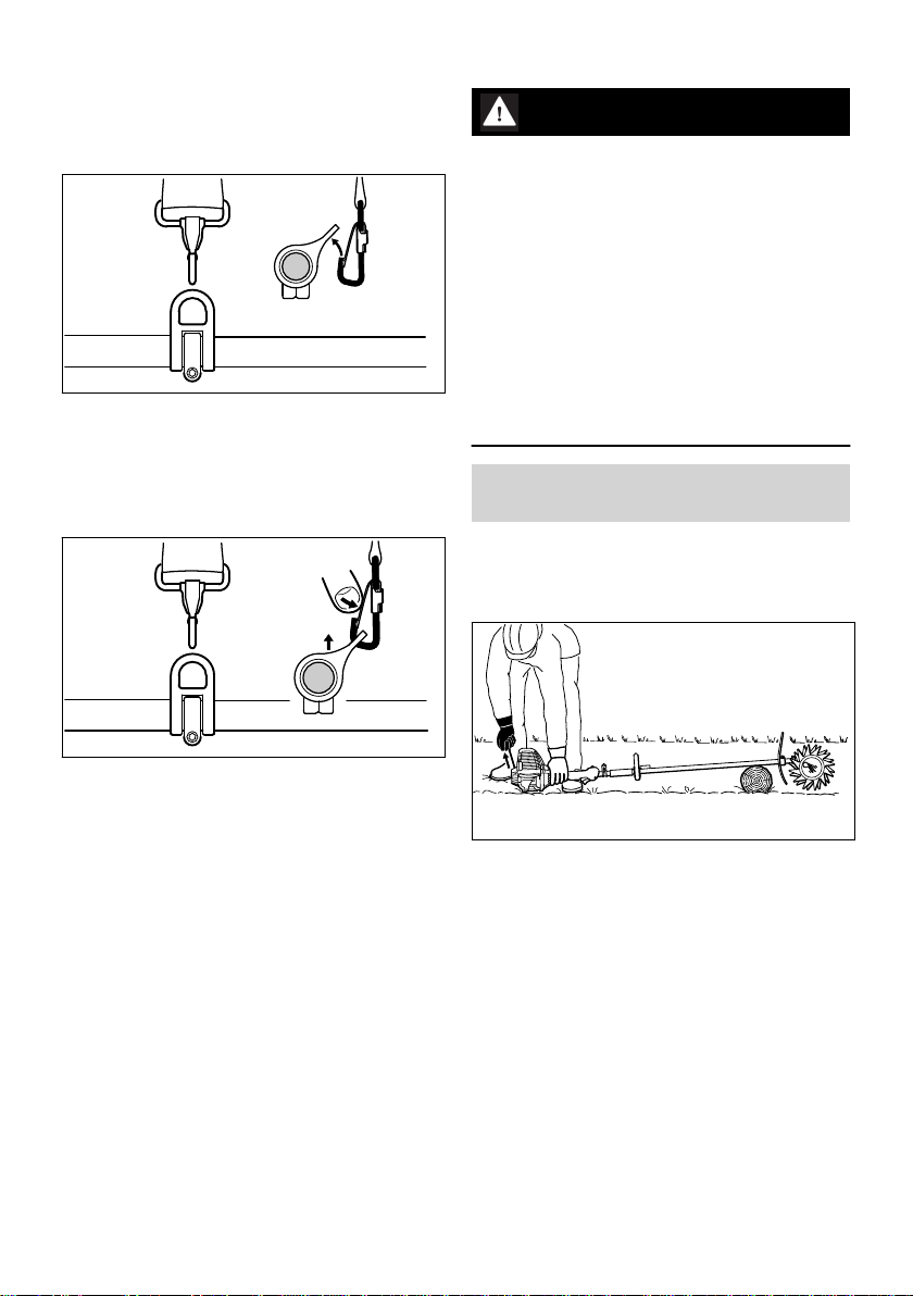
8 Fitting the Harness......................................9
9 Starting / Stopping the Engine.................. 10
10 Storing the Machine.................................. 11
11 Maintenance and Care..............................11
12 Minimize Wear and Avoid Damage...........11
13 Main Parts.................................................12
14 Specifications............................................12
15 Maintenance and Repairs......................... 13
16 Disposal.................................................... 13
17 EC Declaration of Conformity................... 13
18 UKCA Declaration of Conformity.............. 14
1 KombiSystem
In the STIHL KombiSystem a number of different
KombiEngines and KombiTools can be com‐
bined to produce a power tool. In this instruction
manual the functional unit formed by the Kom‐
biEngine and KombiTool is referred to as the
power tool.
Therefore, the separate instruction manuals for
the KombiEngine and KombiTool should be used
together for the power tool.
Always read and and make sure you understand
both instruction manuals before using your
power tool for the first time and keep them in a
safe place for future reference.
2 Guide to Using this Manual
2.1 Pictograms
All the pictograms attached to the machine are
shown and explained in this manual.
2.2 Symbols in text
WARNING
Warning where there is a risk of an accident or
personal injury or serious damage to property.
NOTICE
Caution where there is a risk of damaging the
machine or its individual components.
2.3 Engineering improvements
STIHL's philosophy is to continually improve all
of its products. For this reason we may modify
the design, engineering and appearance of our
products periodically.
Therefore, some changes, modifications and
improvements may not be covered in this man‐
ual.
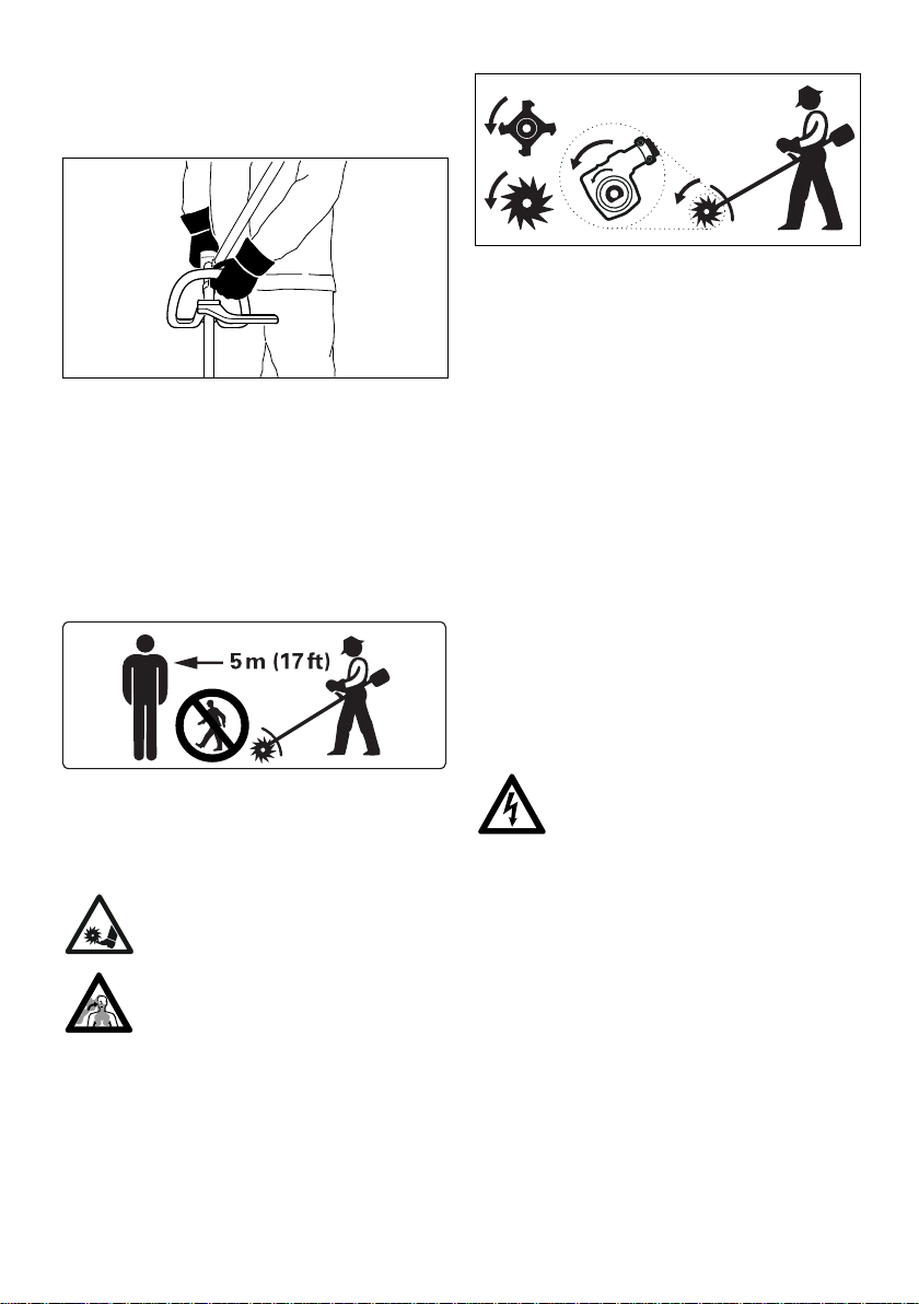
3 Safety Precautions and
Working Techniques
Special safety precautions must be
observed when working with the culti‐
vator because its pointed and sharp-
edged rotor blades rotate at high
speed.
Always read and and make sure you
understand both user manuals (Kom‐
biEngine and KombiTool) before
using your power tool for the first time
and keep them in a safe place for
future reference. Non-compliance
with the user manuals may cause
serious or even fatal injury.
Lend or rent your machine only to persons who
are familiar with this model and its operation – do
not lend or rent your machine without the Kom‐
biEngine and KombiTool user manuals.
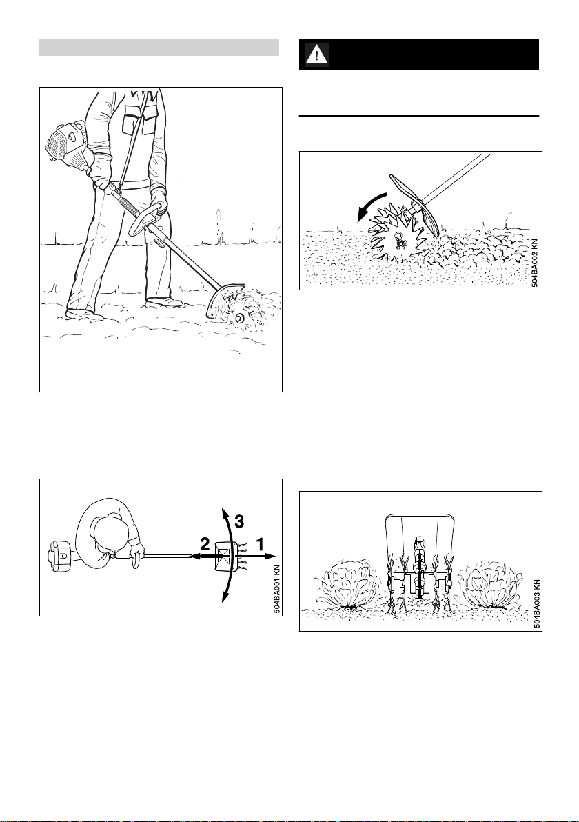
Use the cultivator only for tilling previously culti‐
vated, packed or loose soil, furrowing and work‐
ing in mulches.
The machine must not be used for any other pur‐
poses – risk of accident!
Only mount rotor blades and accessories that
are explicitly approved for this power tool by
STIHL or are technically identical. If you have
any questions in this respect, consult your
dealer.
Use only high-quality parts and accessories. Oth‐
erwise, there is a risk of accidents and damage
to the machine.
English
2 0458-478-0121-D
© ANDREAS STIHL AG & Co. KG 2022
0458-478-0121-D. VA0.G22.
Printed on chlorine-free paper
Printing inks contain vegetable oils, paper can be recycled.
Original Instruction Manual
0000000666_022_GB