STIHLER ELECTRONIC ASTOTHERM plus Setup guide

ASTOTHERM®plus
Blood and Infusion Warmer
Models AP200, AP220 and AP260
Models AP200S, AP220S and AP260S with ASTOLINE
Repair Instructions
REVISION 6, 03/2010
STIHLER ELECTRONIC GmbH
Julius-Hoelder-Strasse 36
D-70597 Stuttgart
Phone: +49 (0)711-720670
Fax: +49 (0)711- 7206757 Part-No. 9950.9000.12

ASTOTHERM PLUS Repair Instructions
Page 2 Revision: 6 – 03/2010

ASTOTHERM PLUS Repair Instructions
Revision: 6 – 03/2010 Page 3
Table of Contents
1TECHNICAL DESCRIPTION...............................................................................................................................5
1.1 General ............................................................................................................................................................5
1.2 Structure ..........................................................................................................................................................6
1.3 Description of the electronics...........................................................................................................................7
1.4 Technical Data.................................................................................................................................................9
1.5 Terminal connecting plan...............................................................................................................................11
1.6 ASTOTHERM PLUS spare parts...................................................................................................................12
2GENERAL GUIDELINES AND PRINCIPLES FOR THE REPAIR OF ASTOTHERM PLUS BLOOD AND
INFUSION WARMERS......................................................................................................................................19
2.1 Technical Service and Ordering Spare Parts ................................................................................................19
2.2 Guarantee repairs..........................................................................................................................................19
2.3 Liability...........................................................................................................................................................19
2.4 Important instructions.....................................................................................................................................20
2.5 Procedure for ASTOTHERM PLUS repairs ...................................................................................................21
3CLEANING AND DISINFECTING .....................................................................................................................22
4FUNCTIONAL CHECK......................................................................................................................................22
4.1 Check display devices (LCD and LED):.........................................................................................................23
4.2 Check heating-up time...................................................................................................................................23
4.3 Check display temperature fluctuation...........................................................................................................23
4.4 Check temperature in control state................................................................................................................24
4.5 Test temperature overshoot on heating.........................................................................................................24
4.6 Alarm test functions .......................................................................................................................................25
4.7 Checking safety cut-offs.................................................................................................................................25
4.8 Measuring resistance of ASTOLINE active insulation ...................................................................................27
4.9 Testing ASTOLINE connection......................................................................................................................27
5TROUBLESHOOTING.......................................................................................................................................28
6DISMANTLING ..................................................................................................................................................30
6.1 Dismantling for troubleshooting in assemblies ..............................................................................................30
6.2 Dismantling bottom part assembly.................................................................................................................31
6.2 Dismantling bottom part assembly.................................................................................................................32
6.3 Dismantling the top part assembly.................................................................................................................33
6.4 Dismantling the heat exchanger cylinder assembly.......................................................................................33
6.5 Dismantling the device fixing assembly .........................................................................................................34
7ASSEMBLING THE DEVICE.............................................................................................................................35
7.1 Assembling the device fixing assembly .........................................................................................................35
7.2 Assembling the heat exchanger assembly ....................................................................................................35
7.3 Assembly of the top part assembly................................................................................................................37
7.4 Assembling the bottom part assembly...........................................................................................................39
7.5 Final assembly of assemblies........................................................................................................................41
8ELECTRICAL SAFETY TEST...........................................................................................................................43
9CONTINOUS DUTY TEST.................................................................................................................................44
10 RETURN AND/OR DISPOSAL OF DEVICES OR ASSEMBLIES....................................................................44
11 APPENDIX.........................................................................................................................................................45

ASTOTHERM PLUS Repair Instructions
Page 4 Revision: 6 – 03/2010
User information:
Test results which must be achieved to ensure safe operation are outlined by a frame.
The description for dismantling covers every possible assembly group and step. If a defective
component or an assembly group are to be replaced, only the steps necessary for this should
be performed.

ASTOTHERM PLUS Repair Instructions
Revision: 6 – 03/2010 Page 5
1 Technical description
1.1 General
Applications
The ASTOTHERM PLUS allows fluids supplied to patients to be heated, either to avoid or reduce
hypothermia or to increase well-being. Applications include transfusions, infusions, dialysis,
haemofiltration and apheresis.
The warmer works in accordance with the principle of flow heating, i.e. the heat is transmitted by the
heat exchanger via the sterile infusion extension to the fluid flowing within it.
If the full heating capacity is not required, two infusion extensions can also be inserted into the first and
second halves of the heat exchanger. A check on heat exchanger temperature at the inlet and outlet
avoids fluids being overheated, even if they have different inlet temperatures.
The patented heat protection sleeve insulates the heat exchanger cylinder and the infusion extension
against the effects of ambient cold (e.g. air-conditioning systems) and thus increases the degree of
efficiency. There is an opening in the centre of the heat protection sleeve for use of a second infusion
extension. This is where extensions can be routed in and out and secured with the hand grips.
Overheating is reliably prevented by the following measures:
C2 separate temperature sensors for temperature control, temperature display and excessive
temperature cut-off,
Can additional independent temperature sensor for excessive temperature cut-off,
Coptical and acoustic alarms.
On models 220(S) and 260(S), the temperature of the ASTOTHERM PLUS can be set alternatively at
three fixed temperature steps up to 43 C. On the model 200(S), the temperature is fixed at 40 C. The
temperature display always shows the current mean temperature of the heat exchanger.
Heating of the medium is based on flow speed and inlet temperature. For an optimum heat transfer we
recommend the original infusion extension ASTOTUBE. (see outlet temperature diagrams in the operating
instructions).
If on the models 220(S) and 260(S) the displayed temperature of the heat exchanger drops by more than
4 C below the selected set temperature, the inadequate temperature alarm is activated. On the model
200(S), the inadequate temperature alarm is fixed at 32 C.

ASTOTHERM PLUS Repair Instructions
Page 6 Revision: 6 – 03/2010
There are ASTOTHERM PLUS in the following variations
Order no Heat exchanger
groove
Temperature Power
consumption
ASTOLINE
actively-heated
insulation up to
the patient
AP 200* 4 mm 40°C (fixed) 250 W -
AP 200 S* 4 mm 40°C (fixed) 250 W U
AP 220
4 mm
37°C, 39°C, 41°C (selectable)
or
39°C, 41°C, 43°C (selectable)
450 W
-
AP 220 S
4 mm
37°C, 39°C, 41°C (selectable)
or
39°C, 41°C, 43°C (selectable)
450 W
U
AP 260
6,8 mm
37°C, 39°C, 41°C (selectable)
oder
39°C, 41°C, 43°C (selectable)
450 W
-
AP 260 S
6,8 mm
37°C, 39°C, 41°C (selectable)
oder
39°C, 41°C, 43°C (selectable)
450 W
U
*no more in the actual sales program
Description of ASTOLINE (optional accessory)
Using the active ASTOLINE insulation, it is possible to limit cooling of the fluid en route from the warmer to
the patient. The heated flexible silicone body surrounds the infusion extension over a distance of up to 130
cm, ensuring that the part of the infusion line which would otherwise be exposed to the cool ambient air is
both insulated and heated. Its special shape also enables infusions and transfusions to be observed all the
way to the patient.
1.2 Structure
In the top part of the housing underneath the front panel is the board with the components for electronic
control, the keys for operation and the associated LEDs and LCD for actual and selected temperature
displays. The board is operated exclusively with low-voltage power.
Depending on model type, the heat exchanger cylinder has either 11 (models 200(S) and 220(S)) or 9
windings (model 260(S)). Approximately 40 cm of infusion extension are required for one winding. The
heating system is attached to the inner surface of the aluminium heat exchanger cylinder. The three
temperature sensors for temperature control, display and safety cut-offs are located in the end faces of the
cylinder.
The transformer board is inserted in the heat exchanger cylinder. On this board are the fuses, the
connections for the mains cable and the heating and the heating control LED.
WARNING! This board is live (100 V AC to 240 V AC)!
The transformer board is secured in the heat exchanger cylinder by the intermediate ring and the fixing
strip.
A universal mounting is fitted to the bottom part of the housing, allowing the device to be attached to an
infusion stand (dia. 12 mm to dia. 35 mm) or to a standard medical rail. Warmers with ASTOLINE active
insulation (models 200S, 220S and 260S) have the board and the device socket for the ASTOLINE fitted in
the bottom part.

ASTOTHERM PLUS Repair Instructions
Revision: 6 – 03/2010 Page 7
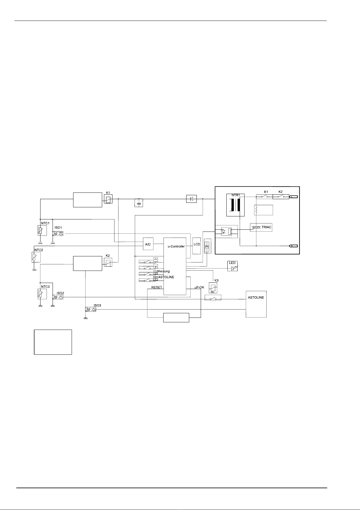
1.3 Description of the electronics
CTemperature control:
The temperature at the heat exchanger cylinder is controlled by a control unit consisting of a
microprocessor, an A/D converter and a triac unit. The actual temperature is determined by two NTC
sensors at the inlet (NTC1) and outlet (NTC2) (cf. Fig. 1, Block Diagram).
CTemperature display:
The actual temperature is displayed in the LCD as a mean value. At a temperature below 15 C, only
three bars at the bottom are shown and above 50 C, only three bars at the top. The three small displays
on the 220(S) and 260(S) models show the user-selectable temperatures. The frame outlines the current
selection according to which the temperature of the heat exchanger is being controlled.
On the model 200(S), the temperature of the heat exchanger is fixed.
CSafety cut-off at warmer inlet (heat exchanger rear side):
The safety cut-off at the warmer inlet is a device independent of the microcontroller. It checks whether NTC1
is hotter than the alarm limit (temperature value of second excessive temperature cut-off, see Section 1.4) In
the event of an alarm, the safety cut-off switches off relay K1. This interrupts the heating current and the
power supply for K1 and K2. Drop-out of the relay is indicated by the flashing alarm LED and the alarm tone.
If the heat exchanger cylinder cools to below the alarm limit, the device can be re-started manually. NTC1
cannot be affected by any conceivable defect of the safety cut-off at the warmer outlet or of NTC3.
CSafety cut-off at warmer outlet (heat exchanger front side):
The safety cut-off at the warmer outlet works according to the same principle as the safety cut-off at the inlet,
though it checks NTC3 (temperature value of the first excessive temperature cut-off, see Section 1.4) located
at the outlet and controls relay K2. NTC3 cannot be affected by any conceivable defect of the control system,
the safety cut-off at the warmer inlet, NTC1 or NTC2. The drop-out of the relay is indicated by the flashing
alarm LED and the alarm tone. If the heat exchanger cylinder cools to below the alarm limit, the device can
be re-started manually.
CTest devices:
Pressing the Start key checks whether relays K1 and K2 reliably cut power if so required. A fault signal is
sent to the safety cut-off at the warmer inlet followed by the safety cut-off at the warmer outlet. The
safety cut-offs react with an audible click. Following a successful test, the device switches on the
heating.
With alarm tests 1 and 2, the safety cut-offs at the warmer inlet and outlet can be tested individually (cf.
operating instructions, Section “PERIODICALLY RECURRING TEST MEASURES”).
CEEPROM memory:
An EEPROM is provided to store constants and operating states. Calibration data are also stored here.
ASTOTHERM PLUS Repair Instructions
Page 8 Revision: 6 – 03/2010
CWatchdog device:
The microprocessor is continuously monitored by a so-called watchdog circuit. If the microprocessor
becomes defective due to a malfunction, the watchdog circuit emits a signal and the device goes to
stand-by mode.
CMains power failure bridging:
This is used to restart the device automatically in the previously selected state in the event of a brief
power failure. Automatic start is effected in the event of a power failure lasting up to 5 seconds, 30
seconds at most.
CASTOLINE active insulation:
ASTOLINE is an auxiliary heating system controlled by current and voltage. If voltage or current are
above or below the permissible limit values, an alarm is activated. The board is operated with low-voltage
power.
Fig. 1 Electronics block diagram
Safety cut-off at
warmer outlet
Safety cut-off at
warmer inlet
Watch-Dog
Heater
Power supply
electronic
ASTOTHERM PLUS Repair Instructions
Revision: 6 – 03/2010 Page 9
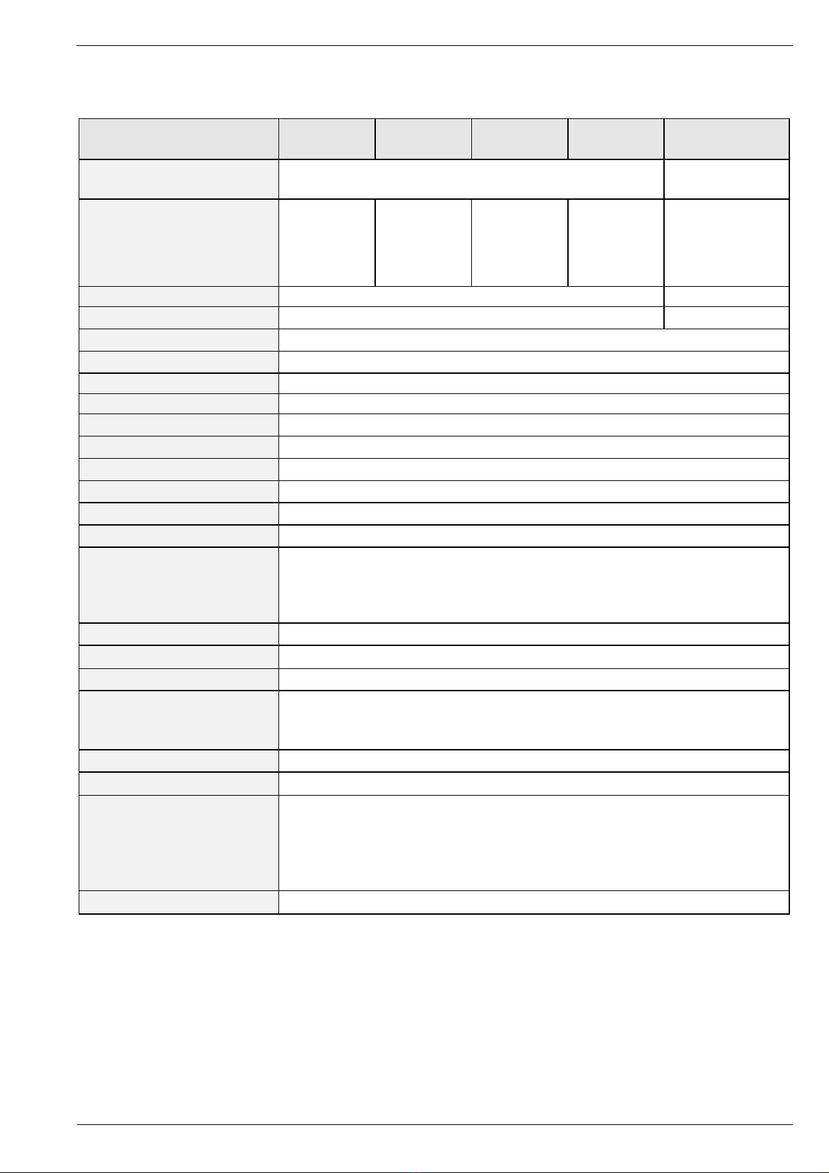
1.4 Technical Data
1.4.1 ASTOTHERM PLUS 200 and 200S
ASTOTHERM PLUS 200(S)
AP200(S) EU
AP200(S) UK
AP200(S) CH
AP200(S) DK
AP200(S) NA
Line voltage 230-240 VAC "10%
47-63 Hz
100-115 VAC "10%
47-63 Hz
Power supply cord
SCHUKO -
plug
H 05 VVF
3x0.75
BS - plug
13A Fuse
H 05 VVF 3x1
Schweiz plug
H 05 VVF
3x0,75
DK - plug
DK2-Ia, DK2-
5a
H 05 VVF
3x0.75
Hospital Grade Plug
NEMA 5-15P
SJO, SJT 18/3
Impedance of protective earth ≤0.2 Ohm ≤0.2 Ohm
Insulation resistance > 2 MOhm > 2 MOhm
AC leakage current
≤0.2 mA
Primary Fuses 2 x 4 A
Secondary Fuses 2 x 0.63 A
Power input 250 W
Selfstart after mains power failure 5 to 30 sec.
Protection class I
Protection level (IEC 601-1) defibrillation-proof applied part of type B
Humidity protection IPX4
Classification as per appendix IX IIb (Rule 9)
UMDNS Code 10-447
Dimensions
height
width
depth
145 mm
135 mm
295 mm
Weight 2.9 kg
Warm- up time approx. 1 min (20 C to 35 C)
Operating mode continous operation
Permissible ambient temperature
for operation
for storage
+16 C to +30 C
-40 C to +70 C
Ambient operating humidity 10 % to 90 %
Operation temperature 40 C ("0.5 °C)
1. safety cut-off
2. safety cut-off
heater bimetal cut-off
42.5 C ("0.5 °C)
43.5 C ("0.5 °C)
65 C ("5 °C)
inadequate temperature alarm below 32 C
ASTOTHERM PLUS Repair Instructions
Page 10 Revision: 6 – 03/2010
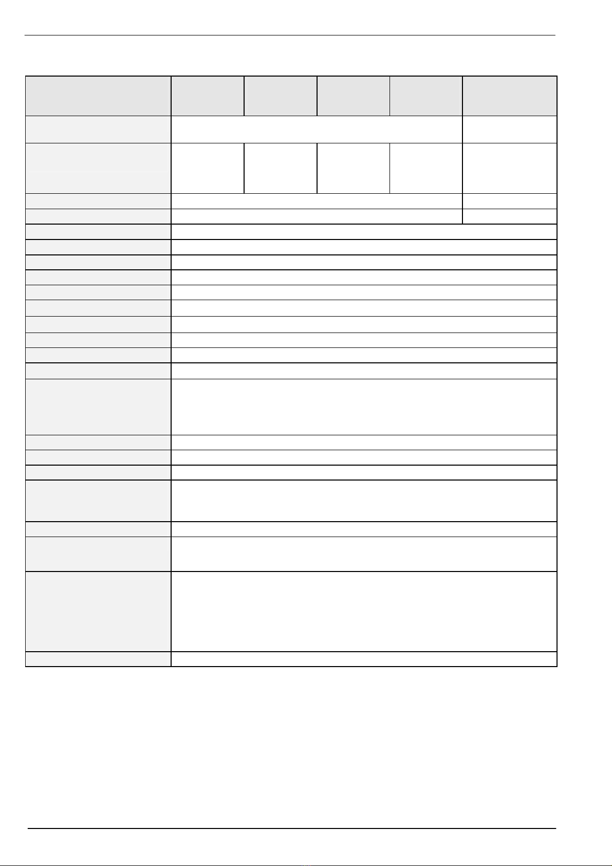
1.4.2 ASTOTHERM PLUS 220, 220S and 260, 260S
ASTOTHERM PLUS 220(S)
ASTOTHERM PLUS 260(S)
AP220(S) EU
AP260(S) EU
AP220(S) UK
AP260(S) UK
AP220(S) CH
AP260(S) CH
AP220(S) DK
AP260(S) DK
AP220(S) NA
AP260(S) NA
Line voltage 230-240 VAC "10%
47-63 Hz
100-115 VAC "10%
47-63 Hz
Power supply cord
SCHUKO-
plug
H 05 VVF
3x0.75
BS - plug
13A Fuse
H 05 VVF 3x1
Swiss plug
H 05 VVF
3x0.75
DK-plug
DK2-Ia, DK2-5a
H 05 VVF
3x0.75
Hospital Grade Plug
NEMA 5-15P
SJO, SJT 18/3
Impedance of protective earth
≤0.2 Ohm
≤0.2 Ohm
Insulation resistance > 2 MOhm > 2 MOhm
AC leakage current
≤0.2 mA
Primary Fuses 2 x 4 A
Secondary Fuses 2 x 0.63 A
Power input 450 W
Selfstart after mains power failure 5 to 30 sec.
Protection class I
Protection level (IEC 601-1) defibrillation-proof applied part of type B
Humidity protection IPX4
Classification as per appendix IX IIb (Rule 9)
UMDNS Code 10-447
Dimensions
height
width
depth
145 mm
135 mm
295 mm
Weight 2.9 kg
Warm- up time approx. 1 min (20 C to 35 C)
Operating mode continous operation
Permissible ambient temperature
for operation
for storage
+16 C to +30 C
-40 C to +60 C
Ambient operating humidity 10 % to 90 %
Operation temperature 37 C ("0,5°C) / 39 C ("0,5 °C) / 41 C("0,5 °C) up to SN ≤5000
or
39 C ("0.5°C) / 41 C ("0.5 °C) / 43 C("0.5 °C) from SN ≥5001
1. safety cut-off
2. safety cut-off
heater bimetal cut-off
41°C-devices: 42.5 C ("0.5 °C)
43°C-devices: 45.5 C ("1°C)
41°C-devices: 43.5 C ("0.5 °C)
43°C-devices: 46.0 C ("1 °C)
65 C ("5 °C)
inadequate temperature alarm 4 C ("0.5 °C) below operation temperature
ASTOTHERM PLUS Repair Instructions
Revision: 6 – 03/2010 Page 11
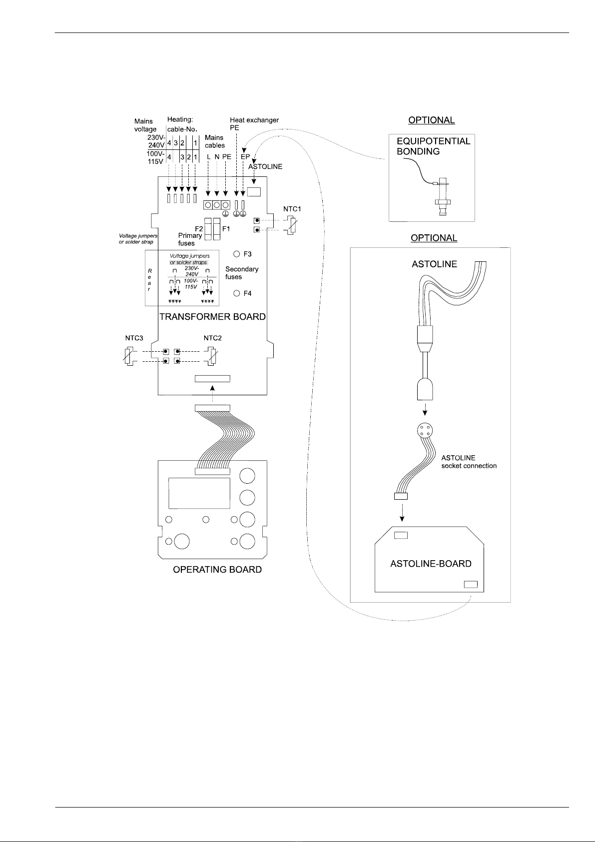
1.5 Terminal connecting plan
Fig. 2 Connections between electronic components
ASTOTHERM PLUS Repair Instructions
Page 12 Revision: 6 – 03/2010
1.6 ASTOTHERM PLUS spare parts
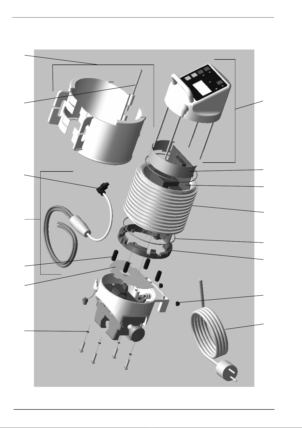
Fig. 3 Cross section of the ASTOTHERM PLUS
20
8
33
2318
31
34
1
22
7
21
1914
10
12
ASTOTHERM PLUS Repair Instructions
Revision: 6 – 03/2010 Page 13
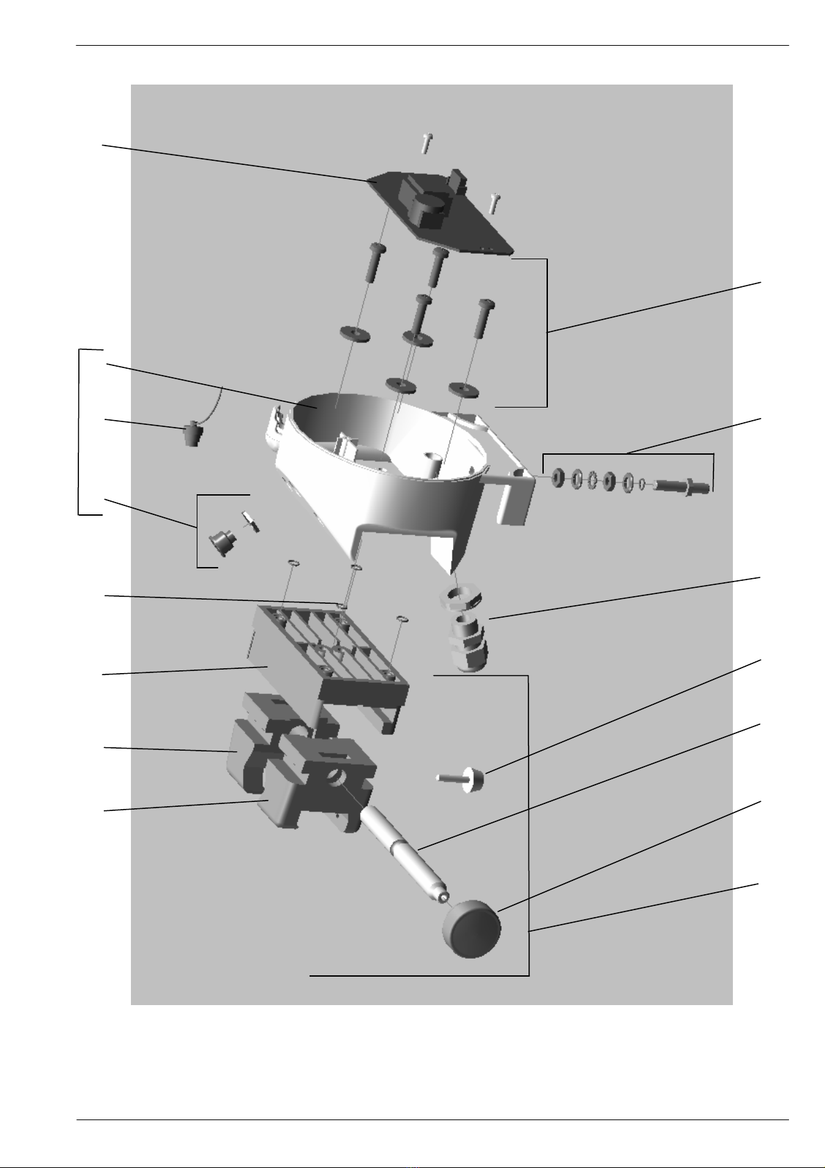
Fig. 4 Cross-section of bottom part assembly with optional components
13a
30
13
28
29
3517
25
16
(27)
32
11
2415
26
27
ASTOTHERM PLUS Repair Instructions
Page 14 Revision: 6 – 03/2010
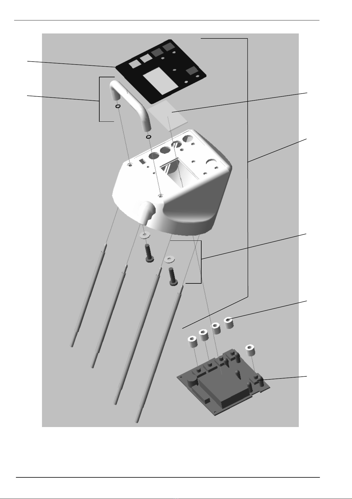
Fig. 5 Cross-section of top part assembly with optional components
4
2
3
1
(2)
6
5
ASTOTHERM PLUS Repair Instructions
Revision: 6 – 03/2010 Page 15
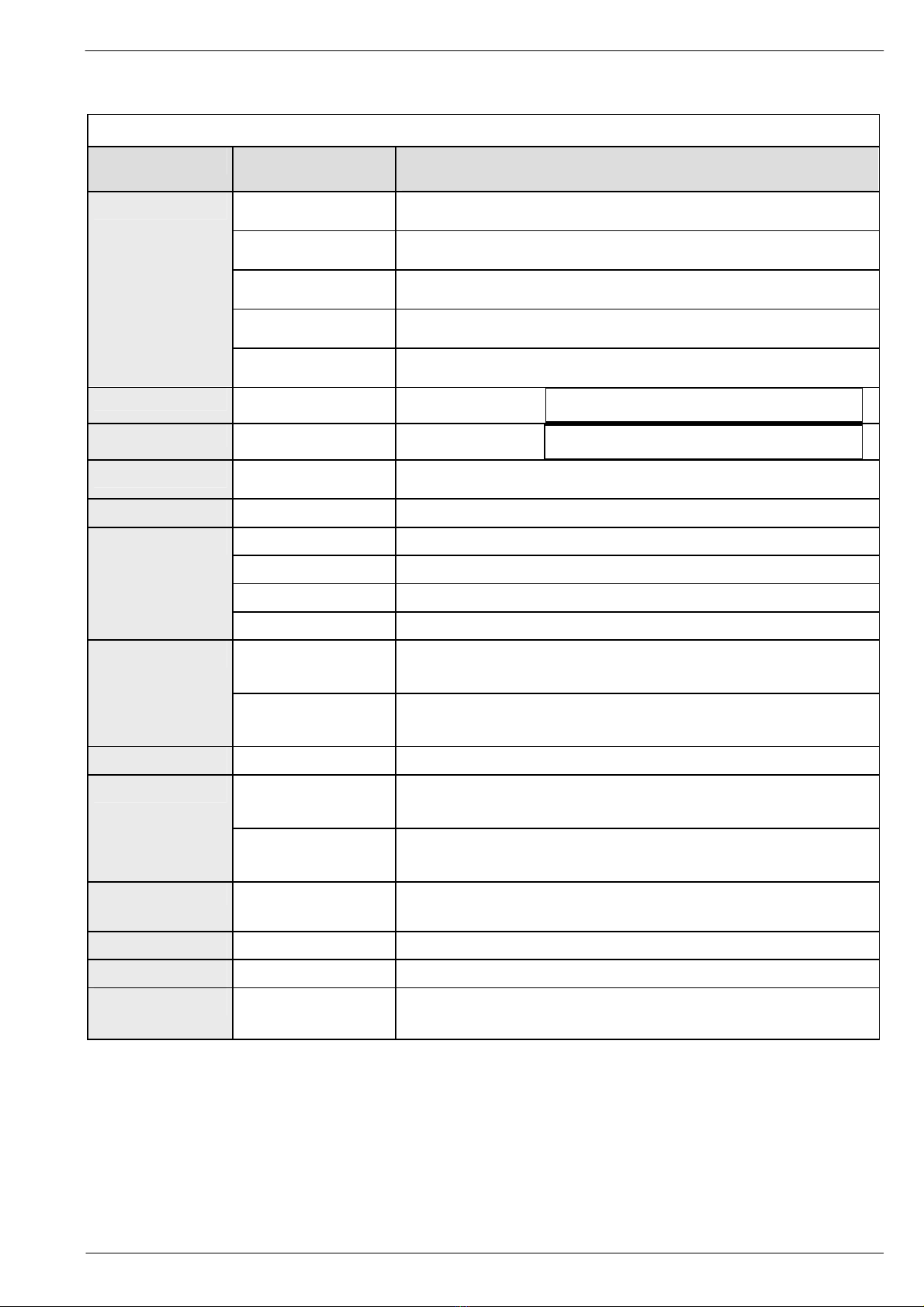
ASTOTHERM PLUS spare parts
When ordering please indicate always model number and serial number!
No.
Order number
Name
consist of
9751.4205.00
TOP PART OF HOUSING AP 200
complete with handle, bolts and front panel
9750.4205.00
TOP PART OF HOUSING AP 220/260
complete with handle, bolts and front panel
9751.4202.00
TOP PART OF HOUSING AP 200S
complete with handle, bolts and front panel
9750.4202.00
TOP PART OF HOUSING AP 220S
complete with handle, bolts and front panel
1
9770.4202.00
TOP PART OF HOUSING AP 260S
complete with handle, bolts and front panel
n.g.
9750.8240.00
AL-Holder 4 mm
with fastening material
n.g.
9750.8241.00
AL-Holder 6,8 mm
with fastening material
2
9750.4202.14
HANDLE
with fastening material
3
9750.4200.13
DISPLAY COVER
9751.4200.05
FRONT PANEL AP 200
9751.4200.02
FRONT PANEL AP 200S
9750.4200.05
FRONT PANEL AP 220/260
4
9750.4200.02
FRONT PANEL AP 220S/260S
9750.2201.01-M841
OPERATING BOARD for M841 NTCs 1) 2) 3)
(red or black NTC wire insulation)
tested and adjusted for Type
5
9750.2201.01-Glas
OPERATING BOARD for glass NTCs 1) 2) 3)
(white NTC wire insulation)
tested and adjusted for Type
6
9750.2200.14
KEY EXTENSION (1 Piece)
9750.2101.01-M841
TRANSFORMER BOARD for M841 NTCs (41°C) 1) 4) 5)
(red or black NTC wire insulation)
tested
7
9750.2101.01-Glas
TRANSFORMER BOARD for glass NTCs (41°C) 1) 4) 5)
(white NTC wire insulation)
tested
0450.2101.43
TRANSFORMER BOARD (43°C) 1) 4) 5)
(white NTC wire insulation)
tested
8
9750.8100.02
AXLE HEAT PROTECTION SLEEVE
10
8510.0305.01
BUFFER (2 Pieces)
11
9750.4100.09
CABLE GLAND PG9
1Cable gland
1Counter nut
only from SN: BSEU1017, BSUK1021, BSCH1012, BSNA1001,
DSEU1323, DSUK1043, DSCH1012, DSNA1054
only from SN: HSEU1015, HSUK1018, HSCH1001, HSNA1015
ASTOTHERM PLUS Repair Instructions
Page 16 Revision: 6 – 03/2010
When ordering please indicate always model number and serial number!
9750.4100.10
POWER SUPPLY CORD SCHUKO
1Power supply cord SCHUKO
1Cable tie 90mm
9750.4100.12
POWER SUPPLY CORD GREAT BRITAIN
1Power supply cord GREAT BRITAIN
1Cable tie 90mm
9750.4100.16
POWER SUPPLY CORD SWITZERLAND
1Power supply cord SWITZERLAND
1Cable tie 90mm
12
9750.4100.17
POWER SUPPLY CORD USA
1Power supply cord USA
1Sticker GROUNDING
1Cable tie 90mm
9750.4100.00
BOTTOM PART OF HOUSING AP 200/220/260
1Bottom part
1Sticker ASTO
2Buffer
2Cable tie 90mm
13
9750.4101.00
BOTTOM PART OF HOUSING AP 200/220/260 - PA
1Bottom part with drill-hole for equipotential bonding
1Sticker ASTO
2Buffer
2Cable tie 90mm
9750.4102.10
BOTTOM PART OF HOUSING AP 200S/220S/260S WITH ASTOLINE
DEVICE SOCKET
1Bottom part with drill-hole for ASTOLINE socket connector
1AL-Device Socket
1AL arrow sticker
1Sticker ASTO
2Buffer
2Cable tie 90mm
1Protective cap
1Crimp connector
13a
9750.4103.10
BOTTOM PART OF HOUSING AP 200S/220S/260S - PA WITH
ASTOLINE DEVICE SOCKET
1Bottom part with drill-hole for ASTOLINE socket connector
and equipotential bonding
1AL-Device Socket
1AL arrow sticker
1Sticker ASTO
2Buffer
2Cable tie 90mm
1Protective cap
1Crimp connection
14
9750.4300.01
INTERMEDIATE RING
15
9750.5100.04
THREADED SHAFT
16
9750.5102.00
CLAMP RIGHT
1Clamp right
1Rectangular nut right
1Pad
17
9750.5100.01
BASEPLATE
1Base plate
1Identification label
18
9750.4300.02
SPACING BOLT (1 Piece)
19
9720.3725.02
O-RING 114.02 x 1,78 (2 Pieces)
20
9750.8100.00
HEAT PROTECTION SLEEVE AP
2Half part Heat protection sleeve
1Axle
2Sticker ASTOTHERM PLUS
1Fixing cord
ASTOTHERM PLUS Repair Instructions
Revision: 6 – 03/2010 Page 17
When ordering please indicate always model number and serial number!
9750.3132.00-41 HEAT EXCHANGER COMPLETE
GROOVE 4 MM (AP200, 220) 40/41°C 1) 6) 7)
1Earth conductor 200mm mounted
4Insulating cover
1Ferrit-Ring
2Cable tie 90mm
9750.3132.00-43 HEAT EXCHANGER COMPLETE
GROOVE 4 MM (AP220) 43°C 1) 6) 7)
1Earth conductor 200mm mounted
4Insulating cover
1Ferrit-Ring
2Cable tie 90mm
9770.3132.00-41 HEAT EXCHANGER COMPLETE
GROOVE 6.7 MM (AP260) 41°C 1) 6) 7)
1Earth conductor 200mm mounted
4Insulating cover
1Ferrit-Ring
2Cable tie 90mm
21
9770.3132.00-43 HEAT EXCHANGER COMPLETE
GROOVE 6.7 MM (AP260) 43°C 1) 6) 7)
1Earth conductor 200mm mounted
4Insulating cover
1Ferrit-Ring
2Cable tie 90mm
n.g. 9750.8110.01 FIXING CORD HEAT PROTECTION SLEEVE
n.g. 9524.2620 FERRIT-RING
22 9950.2100.20 FIXING STRIP
9750.8230.00 ASTOLINE ACTIVE INSULATION 4 MM
23
9750.8231.00 ASTOLINE ACTIVE INSULATION 6.8 MM
24 9850.5100.10 KNURLED SCREW
25 9750.5103.00 CLAMP LEFT
1Clamp left
1Rectangular nut left
1Pad
26 9750.5104.00 HAND WHEEL
1Hand wheel with Nut M8
1Grip cover
1Head screw M4x8
1Washer A4,3
27 9750.5101.00 DEVICE FIXING AP COMPLETE
28 9750.8230.17 PROTECTION CAP for ASTOLINE device socket
1Protection cap
1Crimp connector
29 9750.8230.02 ASTOLINE DEVICE SOCKET
1AL device socket
1AL arrow sticker
1Counter nut
30 9750.8220.03 ASTOLINE BOARD
1AL-Board
2Pan head tapping screw
31 9750.8240.04 AL-INSULATION PLATE
32 9750.4184.00 EQUIPOTENTIAL RETROFITTING SET
1Earth conductor 150mm
1Connector dia. 6 mm
2Nut M6
2Washer R6,4
1Serrated lock washer V6,4
1O-ring 5x1
1Assembly plan
1Drilling gauge
1Sticker
ASTOTHERM PLUS Repair Instructions
Page 18 Revision: 6 – 03/2010
When ordering please indicate always model number and serial number!
33 9750.8230.20 AL-PLUG (for soldering)
1 AL arrow sticker
34 9750.4201.14 SET O-RINGS 4x1 MM
4 for housing screws
2 for handle
2Cable tie 90mm
35 9750.5101.11 SET O-RINGS 5x1 MM
4 for device fixing AP
1 for equipotential bonding plug
2Cable tie
n.g. 9850.6001.00
PACKAGE AP COMPLETE
1Internal carton
1EPS insert botton
1EPS insert top
1Outer carton
1Sticker package AP blank
n.g. 9850.6003.01 OUTER CARTON SINGLE AP
n.g. 9850.6003.02 OUTER CARTON DOUBLE AP
n.g. 9850.6003.03 OUTER CARTON FOURFOLD AP
TEST-EQUIPMENT
n.g. 9950.9000.02 POWER RESISTORS SET
4Pieces 15 Ohm 10 W "5 %
1Piece 100 Ohm 10 W "5 %
n.g. 9950.9000.03 CD-ROM AP Calibration Software
1 Interface (230 VAC)
1 Instructions “AP Calibration Program”
1 Instructions “Eliminating microprocessor faults”
n.g. 9950.9000.35 Test Thermistor tip 3.5 mm
to measure the temperature dependent on the resistance with multimeter and table
Important details
Because of the different variants and changes due to technical improvement it is
absolutely necessary to indicate the model number (REF) and the serial number (SN).
Only then it is ensured that the desired spare part is delivered in the right configuration.
1)
An exchange of this part requires an adjusting of temperature and display (see chapter 4 of the Repair
Instructions). An exact adjustment can only be made by using the interface and the AP Calibration
Software or by the manufacturer.
2)
Operating boards (only for Glass-NTCs, from Rev. 3.1) can be used alternatively for 40°C or for 41°C or
for 43°C devices by uploading an corresponding data file (to do this the interface and the AP
Calibration Software is necessary).
3)
Operating boards from Rev. 3.1 can be used alternatively for M841-NTC or Glass-NTC devices by
switching a solder jumper.
4)
Because of the different characteristics of M841-NTCs and Glass-NTCs, transformer boards cannot be
used alternatively. They must be ordered and built in for the specific NTC type.
5)
Because of the different excessive temperature cut-offs, transformer boards cannot be used
alternatively for 40/41°C or for 43°C devices.
6)
Because of the different position of the NTCs, heat exchanger cannot be used alternatively for 40/41°C
or for 43°C devices.
7)
Heat exchanger with M841-NTCs are no longer available.
ASTOTHERM PLUS Repair Instructions
Revision: 6 – 03/2010 Page 19
2 General guidelines and principles for the repair of ASTOTHERM PLUS
blood and infusion warmers
2.1 Technical Service and Ordering Spare Parts
STIHLER ELECTRONIC GmbH Tel: +49 (0) 711-720670
Julius-Hoelder-Str. 36 Fax: +49 (0) 711-7206757
70597 Stuttgart www.stihlerelectronic.de
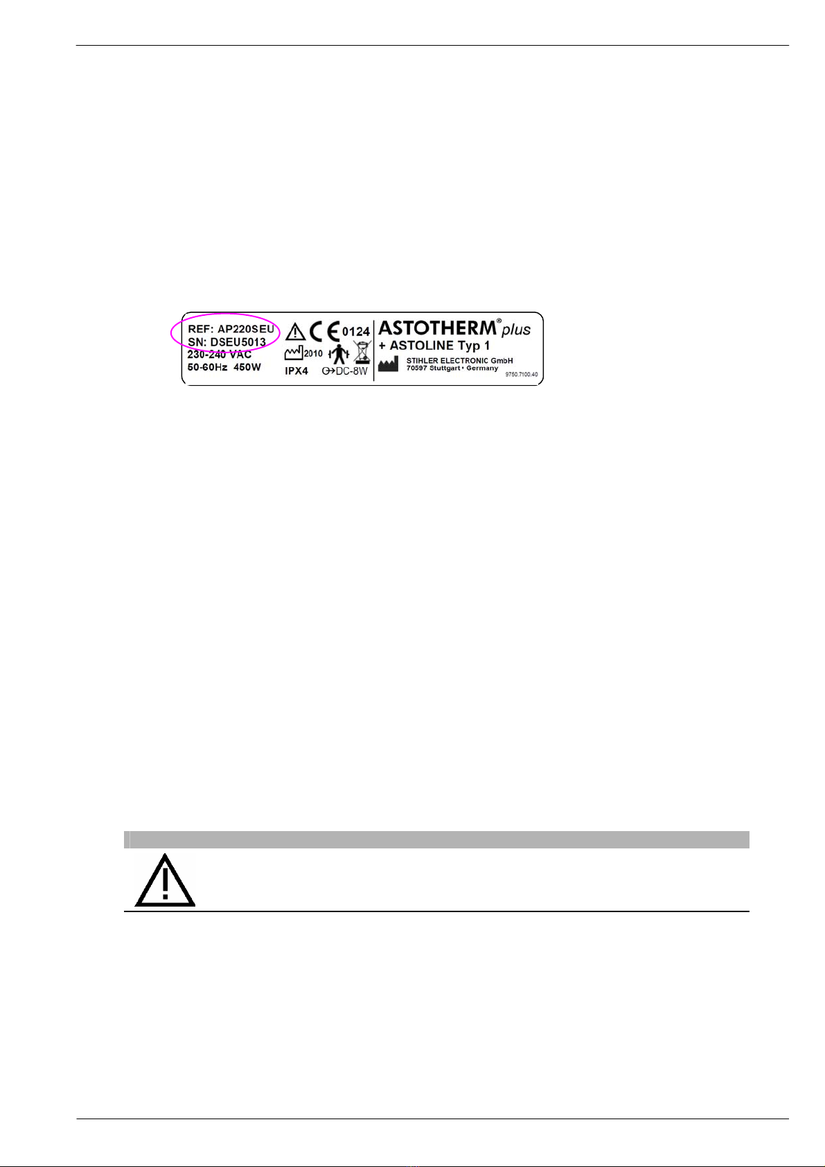
When making requests or ordering spare parts, please state the reference and serial number of
the device in question. You can find them on the device rating plate:
Fig. 6 Information on the rating plate
2.2 Guarantee repairs
A 12-month guarantee is granted. During the guarantee period, the manufacturer will remedy all
defects due to material or manufacturing faults free of charge either by repair or replacement.
This guarantee does not cover any other damage. Damage due to misuse or improper handling,
excessive force or regular wear is not covered by this guarantee. This also applies to
interventions by persons other than those authorised by the manufacturer or if the original
condition is changed.
If damage occurs during the guarantee period, please clean the device and send it to a sales
location near you or directly to STIHLER ELECTRONIC. The costs of transport and packaging are
for the sender's account.
2.3 Liability
The manufacturer shall only be liable for the safety, reliability and performance of the device if all
operating, maintenance and testing procedures comply with the procedures communicated by the
manufacturer and are carried out by properly trained and qualified personnel; if -when necessary-
only original spare parts are used to replace components; if assembly and repairs are only carried
out by authorised personnel or an authorised service centre; if the electrical systems comply with
the locally applicable instructions and regulations and the IEC requirements and if the device is
used in keeping with the instructions of use for the intended purpose and at a suitable location.
CAUTION
The fact that technical documents or spare parts are made available does
not imply any authorisation on the part of the manufacturer to open or
repair the device.
ASTOTHERM PLUS Repair Instructions
Page 20 Revision: 6 – 03/2010
2.4 Important instructions
All tests must be carried out by properly qualified staff, i.e. staff who have the relevant expert
professional training, knowledge and experience and are familiar with the relevant
technologies, standards and local rules and regulations. Personnel who have to assess safety
must be able to recognise any consequences and dangers caused by devices which do not
comply with the requirements.
The measuring equipment must comply with the relevant standards.
All repair activities, all tests carried out and their results must be recorded.
The pattern approval is invalidated if the device is no longer in its original state. You must
therefore use only original spare parts.
Due to the safety risks, electronic PWBs must only be repaired by the manufacturer. If
they are faulty they must always be replaced in their entirety.
Any heat exchanger cylinder is an individual item from a heat engineering point of view, due to its
complex production and the large number of influencing variables (production tolerances in the
manufacture of the heating system, NTCs etc.). For this reason, every electronic temperature
control needs to be specifically matched to “its” heat exchanger cylinder in order to achieve
sufficiently small control fluctuation later on.
The NTCs form the core of the blood warmer. Their sensitivity means that it is prohibited to
change their position or replace them. When dismantling or assembling the device, ensure
that the NTCs/their connecting wires are not damaged.
Defective NTCs may be replaced only by the manufacturer. The complete heat exchanger
cylinder/transformer board/operating board unit needs to be returned for this purpose.
For all thermal test work pay attention to room temperature and ambient effects!
As the control temperature is set accurate to a few tenths of a C, note the following points:
- avoid external effects on the heat exchanger unit /electronics to be measured
- no draughts
- constant room temperature (20 to 26 C)
- keep out of direct sunlight
- keep away from strong light sources
CAUTION
A functional check (see Section 4) and a continuous duty test (see
Section 9) must be performed after any repair to the device.
Other manuals for ASTOTHERM plus
1
This manual suits for next models
6
Table of contents
Other STIHLER ELECTRONIC Medical Equipment manuals


Popular Medical Equipment manuals by other brands


Getinge
Getinge Arjohuntleigh Nimbus 3 Professional Instructions for use

Mettler Electronics
Mettler Electronics Sonicator 730 Maintenance manual

Pressalit Care
Pressalit Care R1100 Mounting instruction

Denas MS
Denas MS DENAS-T operating manual

bort medical
bort medical ActiveColor quick guide

AccuVein
AccuVein AV400 user manual


