Still LiftRunner B frames User manual

Original instructions
Liftrunner
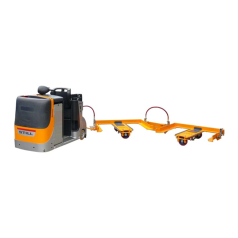
B frames for tugger trains
-
50988046101 EN - 02/2017


Table of contents
g
1 Foreword
General ............................................................ 2
About these operating instructions ........................................ 2
Issuedateandtopicality ................................................ 3
Copyrightandtrademarkrights ........................................... 3
CElabelling ......................................................... 3
EC declaration of conformity in accordance with Machinery Directive ............... 4
Information about the documentation ...................................... 5
Copyright and trademark rights ........................................... 5
Explanation of information symbols used . . ................................. 5
Termsanddefinitions .................................................. 5
Environmental considerations ........................................... 7
Packaging .......................................................... 7
Disposalofunitsandhydraulicoil ......................................... 7
2 Introduction
Use of the tugger train ................................................ 1
0
Intended use ....................................................... 10
Improperuse ....................................................... 10
Requirements for the towtractor ......................................... 11
Residual risk ....................................................... 12
Residualrisk ....................................................... 12
Danger to employees . . ............................................... 12
3Safety
Definition of terms used for responsible persons ............................. 16
Personnel ......................................................... 16
Operatingcompany .................................................. 16
Specialist .......................................................... 17
Basic principles for safe operation ....................................... 17
Warning regarding non-originalparts ..................................... 17
Changes and retrofitting ............................................... 18
Damageanddefectstosafetysystems .................................... 18
Protection type of electricalsystem ....................................... 18
Safety regulations for handling consumables ............................... 19
Oils .............................................................. 19
Hydraulic fluid ...................................................... 20
Disposalofconsumables .............................................. 21
50988046101 EN - 02/2017 I

Table of contents
g
4Overviews
Overall view ........................................................ 24
Bframe ........................................................... 24
Articulatedsteeringsystem ............................................ 24
Trolleys ........................................................... 25
Description ........................................................ 26
Bframes .......................................................... 26
Articulatedsteeringsystem ............................................ 27
Tiller system ....................................................... 28
Standardtiller/articulatedsteeringsystem .................................. 28
Tillerlengths ....................................................... 30
Hose lengths and cable lengths ......................................... 31
Articulated steering system ............................................ 33
Components for two frames - hydraulic system . . . ........................... 33
Components for two frames-electricalsystem .............................. 34
Rigidtillerandhingedtiller(twoframes) ................................... 35
Constructionoverview ................................................ 36
Rigid tiller, hinged tiller and compensating hinge (2+2 frames) ................... 37
Labelling points ..................................................... 38
Identificationplate ................................................... 38
Position ........................................................... 39
Tugger train combinations ............................................. 40
Overview .......................................................... 40
Hydraulicsystem .................................................... 41
Electricalsystem .................................................... 43
BframesandEframeswitharticulatedsteeringsystem ........................ 45
Mixing B or E frames with autarkicEframes ................................ 45
MixingB,CandEframes .............................................. 46
5 Operation
Commissioning the B frames ........................................... 48
Testing before initialcommissioning ...................................... 48
Checksbeforecommissioning .......................................... 48
Safetyregulationsforcommissioning ..................................... 49
Loading the B frames ................................................. 49
UnloadingtheBframes ............................................... 50
ManuallyliftingtheBframes ............................................ 52
Hydraulic system .................................................... 53
Releasingthepressurefromthehydraulicsystem ............................ 53
II 50988046101 EN - 02/2017

Table of contents
g
Hydraulic connection to the trailer ........................................ 53
Connecting the plug connector .......................................... 56
Disconnecting the plug connector ........................................ 56
Electrical system .................................................... 58
Connection assembly for the electrical system .............................. 58
Electrical system error codes ........................................... 59
Assembling the articulated steering system ................................. 60
Assemblingthearticulatedsteeringsystem ................................. 60
Installing and removing thecompensatinghinge ............................. 72
Installing and removing the hinged tiller .................................... 73
Driving ............................................................ 77
Safety regulations when driving ......................................... 77
Drivingoverramps ................................................... 78
Reversetravel ...................................................... 79
Steering angle ...................................................... 80
Roadways ......................................................... 81
MinimumaislewidthsforBframes ....................................... 81
6 Maintenance
Safety regulations for maintenance ....................................... 88
Generalinformation .................................................. 88
Maintenance instructions .............................................. 88
Personnel qualifications ............................................... 89
Workingonthehydraulicequipment ...................................... 89
Checkingthehydraulicsystemforleaks ................................... 89
Maintenance intervals for B frames ....................................... 91
Consumables ...................................................... 92
7 Technical data
B frames - single loadable ............................................. 94
B frames - triple loadable .............................................. 96
50988046101 EN - 02/2017 III


1
Foreword

1Foreword
General
General
About these operating instructions
These operating instructions describe daily
operation of the tugger train in detail and can
be used as a source of information by both
new and trained operators.
The operating instructions are not intended to
be a technical or service manual. For technical
or maintenance issues that are not covered in
these operating instructions, please contact
your authorised service centre.
Manufactured by:
LR Intralogistik GmbH
Siemensstraße 15
84109 Wörth an der Isar
Germany
Distribution and service by:
STILL GmbH
Berzeliusstr. 4
22113 Hamburg
Germany
250
988046101 EN - 02/2017

Foreword 1
General
Issue date and topicality
The issue date of these operating instructions
can be found on the title page.
STILL makes continuous efforts to enhance
and improve its trucks. These operating
instructions are subject to change, and any
claims based on the information and/or
illustrations contained in them cannot be
asserted.
If you require technical support for the vehicle,
please contact the authorised service centre.
Have a good trip, your partner
STILL GmbH
Berzeliusstr. 10
22113 Hamburg, Germany
Copyright and trademark rights
These instructions must not be reproduced,
translated or made accessible to third par-
ties—including as excerpts—except with the
express written approval of the manufacturer.
CE-Symbol
CE labelling
The manufacturer uses CE labelling to indi-
cate that the frame complies with the stan-
dards and regulations valid at the time the
frame was placed on the market. Compliance
is confirmed by the issue of an EC declaration
of conformity. The CE labelling is attached to
the nameplate.
An unauthorised structural change or addition
to the frame can compromise safety, thus
invalidating the EC declaration of conformity.
The EC declaration of conformity must be
carefully stored and made available to the
relevant authorities.
50988046101 EN - 02/2017 3

1Foreword
General
EC declaration of conformity in accordance with Machinery Directive
Declaration
LR Intralogistik GmbH
Siemensstraße 15
84109 Wörth an der Isar
We declare that the
Device description: Corresponding to these operating instructions
Device type: Corresponding to these operating instructions
conforms to the latest version of the Machinery Directive 2006/42/EC.
Personnel authorised to compile the technical documents:
See EC declaration of conformity
LR Intralogistik GmbH
.
450
988046101 EN - 02/2017

Foreword 1
Information about the documentation
Copyright and trademark rights
These instructions must not be reproduced,
translated or made accessible to third par-
ties—including as excerpts—except with the
express written approval of the manufacturer.
Explanation of information symbols
used
DANGER
Indicates procedures that must be strictly adhered
to in order to prevent the risk of fatalities.
WARNING
Indicates procedures that must be strictly adhered
to in order to prevent the risk of injuries.
CAUTION
Indicates procedures that must be strictly adhered
to in order to prevent material damage and/or
destruction.
NOTE
For technical requirements that require
special attention.
ENVIRONMENT NOTE
To prevent environmental damage.
Terms and definitions
Chassis
The chassis is a trailer for picking up loads.
It is suitable for holding trolleys of all sizes.
The frame must be lifted to ensure safe,
low-noise transportation. Depending on the
design, this operation can be carried out using
a hydraulic, pneumatic or electrical system.
The tow tractor for the frames must therefore
50988046101 EN - 02/2017 5

1Foreword
Information about the documentation
be fitted either with a suitable hydraulic power
unit, air compressor or electrical system.
"Self-sufficient" chassis
When using a "self-sufficient" chassis, neither
a hydraulic unit nor an air compressor is
required. These chassis can raise and lower
their load without the need for a hydraulic or
pneumatic supply.
Operating principle: One load wheel on the
frame drives one pump with a tank. The
generated oil pressure is storedinaspring
accumulator. This oil pressure is used to raise
the load and is fed back into the tank when the
load is lowered.
The "self-sufficient" model is only available for
E chassis.
Articulated steering system
An articulated steering system consists of a
rigid tiller and a hinged tiller. The articulated
steering system allows driving on ramps and
stabilises the tugger train in the vertical plane -
prevents the frames from rocking.
Hinged tiller
The hinged tiller connects two articulated
frame steering rigs and the tow tractor to a
tugger train.
Compensating hinge
The compensating hinge is fitted to the first
articulated frame steering rig as a holding
fixture for the hinged tiller on the second
articulated frame steering rig.
Trolley
A rolling platform is pushed into the frame for
transportation. Depending on the design of
the "trolley" and of the frame, a frame can hold
one or more trolleys.
650
988046101 EN - 02/2017

Foreword 1
Environmental considerations
Tugger train
The unit consisting of the frames and a tow
tractor is known as the "tugger train".
Environmental considerations
Packaging
When the chassis are delivered, certain parts
are packaged to provide protection during
transportation. This packaging must be
removed completely prior to commissioning.
ENVIRONMENT NOTE
The packaging material must be properly
disposed of after delivery of the chassis.
Disposal of units and hydraulic oil
It may be necessary to exchange units as part
of maintenance work. Exchanged units must
then be disposed of.
A chassis is made of different materials. Each
of these materials must be
• disposed of,
• treated or
• recycled in accordance with regional and
national regulations.
ENVIRONMENT NOTE
We recommend working with a waste mana-
gement company for disposal of hydraulic oil
or other hazardous materials.
50988046101 EN - 02/2017 7
1Foreword
Environmental considerations
850
988046101 EN - 02/2017

2
Introduction

2Introduction
Use of the tugger train
Intended use
The frames are intended solely for the follo-
wing purpose:
• Picking up and transporting trolleys loaded
with equipment in order to transport them to
a workplace and replace them with empty
trolleys
• A frame must only be loaded with the
trolleys intended for this purpose
• A B frame, C frame or E frame may only
be pulled by a suitably equipped (pneu-
matic/hydraulic/electrical) tow tractor (not
by a truck!)
• An autarkic E frame may only be pulled by
an appropriate tow tractor (not by a truck!).
WARNING
The frames are designed for a maximum speed of
15 km/h.
If a tow tractor is used that can travel faster than
15 km/h, its maximum speed must be limited to 15
km/h in order to guarantee safe operation of the
chassis.
The chassis may only be used for its proper
purpose as set out and described in these
operating instructions!
If the chassis is to be used for purposes
other than those specified in the operating
instructions, the approval of the manufacturer
and, if applicable, the relevant regulatory
authorities must be obtained beforehand to
prevent hazards.
Improper use
The operating company or driver, and not the
manufacturer, is liable for any hazards caused
by improper use.
Use for purposes other than those described
in these operating instructions is prohibited.
• A chassis may not be operated in areas
where there is a risk of fire, explosion or
10 50988046101 EN - 02/2017

Introduction 2
Use of the tugger train
corrosion, or in areas that are particularly
dusty.
• A chassis must not be loaded or unloaded
on slopes or ramps.
• Transportation of people is prohibited
Requirements for the tow tractor
General requirements
The tow tractor must have a steered front axle.
The maximum speed of the tow tractor must
belimitedto15km/h.
The towing jaws of the tow tractor must
correspond with the LR standard:
• C frames: Rockinger towing jaws RO244- 2
• B frames and E frames: bolt = 28.5 mm,
vertical play = 70 mm
It must be ensured that the tow tractor cannot
be moved before all framesarefullyraised.
Hydraulic C frame
• The maximum permitted tractive power of
the tow tractor must not exceed 16,000 N
• A suitable hydraulic power unit with the
following properties must be fitted to the
tow tractor: operating pressure: 180 - 200
bar; flow rate: approx. 10 l/min; coupling in
accordance with ISO 16028
• There must be at least 2litresofhydraulic
oil (HLP46) in the hydraulic system
• The hydraulic connection must be fitted
close to the tow coupling of the tow tractor
Hydraulic B frames and E frames
• The maximum permitted tractive power of
the tow tractor must not exceed 2,000 N
With a reinforced hinged tiller (UPA), the
maximum tractive power of the tow tractor
must not exceed 5000 N
• A suitable hydraulic power unit with the
following properties must be fitted to the
tow tractor: operating pressure: 180 - 200
bar; flow rate: approx. 10 l/min; coupling in
accordance with ISO 16028
• There must be at least 2 litres of hydraulic
oil (HLP46) in the hydraulic system
Pneumatic E frame
• The maximum permitted tractive power of
the tow tractor must not exceed 2,000 N
With a reinforced hinged tiller (UPA), the
maximum tractive power of the tow tractor
must not exceed 5000 N
• Depending on the design of the E frames,
the tow tractor must have a compressor of
the corresponding size:
- For frames with a 600 kg load capacity: 7 bar
working pressure
- For frames with a 1000 kg load capacity: 10
bar working pressure
Electrical B frames and E frames
• The maximum permitted tractive power of
the tow tractor must not exceed 2,000 N
With a reinforced hinged tiller (UPA), the
maximum tractive power of the tow tractor
must not exceed 5000 N
• The tow tractor must have suitable interface
• The tow tractor must have a rechargeable
battery with a voltage of 24 V
• The rechargeable battery must be able to
provide a current of up to 125 A at 24 V for
lifting the frames
• For lowering the frames, the rechargeable
battery must be able to store up to 35 A at
25.5 V
50988046101 EN - 02/2017 11

2Introduction
Residual risk
Autarkic E frame
• The maximum permitted tractive power of
the tow tractor must not exceed 2,000 N
With a reinforced hinged tiller (UPA), the
maximum tractive power of the tow tractor
must not exceed 5000 N
Residual risk
Residual risk
Residual dangers, residual risks
Despite careful work and compliance with
standards and regulations, the occurrence of
other risks when using the chassis cannot be
entirely excluded.
The chassis and all other system components
comply with current safety requirements.
Nevertheless, even when the chassis are
used for their proper purpose and all the
instructions specified here are followed, some
residual risk cannot be excluded.
Even beyond the narrow danger areas of the
chassis, a residual risk cannot be excluded.
Persons in this area must exercise a height-
ened degree of awareness towards the chas-
sis and the tugger train as a whole, so that
they can react immediately in the event of any
malfunction, incident or breakdown etc.
WARNING
All persons that are in the vicinity of the chassis
must be instructed regarding these risks that arise
through use of the chassis.
In addition, attention must be drawn to the safety
regulations in these operating instructions.
The risks can include:
• Escape of consumables due to leakages,
rupture of lines and containers etc.
• Risk of accident when driving over difficult
ground such as gradients, smooth or
irregular surfaces, or poor visibility etc.
• Falling or tripping when loading or unload-
ing the Trolleys into or out of the chassis.
• Human error - Disregarding safety regula-
tions.
• Risk caused by unrepaired damage.
• Risk caused by insufficient maintenance or
testing.
• Risk caused by using the wrong consum-
ables.
• Risk caused by exceeding testing intervals.
The manufacturer is not held responsible for
accidents involving a chassis caused by the
operating company's intentional or negligent
failure to comply with these regulations.
Danger to employees
According to the German workplace safety
ordinance (BetrSichVO) and labour protection
law (ArbSchG), the operating company
must determine and assess hazards during
operation, and establish the occupational
health and safety measures required for
employees. The operating company must
therefore draw up appropriate operating
procedures (§ 6 ArbSchG) and make them
12 50988046101 EN - 02/2017

Introduction 2
Residual risk
available to the driver. These operating
instructions for the frames do not form the
operating procedures. A responsible person
must be appointed.
The structure and equipment of the frames
correspond to the Machinery Directive
2006/42/EC and are therefore identified with
the CE mark. The operating company must,
however, select the frame type and frame
equipment so as to comply with the local pro-
visions for deployment.
The result must be documented(§6Arb-
SchG). When deployment of the frames in-
volves similar hazard situations, the results
may be summarised. This summary is de-
signed to help to meet the requirements of
this regulation. The summary specifies the
primary hazards that, in the event of non-com-
pliance, are the most frequent causes of acci-
dents. If other major hazards are present as
a result of the specific operating conditions,
these hazards must also be taken into consid-
eration.
The conditions of use for the frames are
broadly similar in many plants, so the haz-
ards can be summarised in one overview. The
information provided on this subject by the
relevant employers' liability insurance associ-
ation or national authorities must be observed.
50988046101 EN - 02/2017 13

2Introduction
Residual risk
14 50988046101 EN - 02/2017
Table of contents
Other Still Lifting System manuals