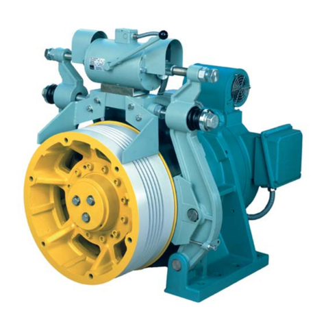
WITTUR HHL-W Line User manual

Home Lift - Elevating platform
Test instructions
Subject to change without notice!
EXCELLENCE IN COMPONENTS
Date
07
/
1
0
/20
11
Sheet 1
Version 1111732001 V02
Approved ISC
Original instructions

Home Lift - Elevating platform
Test instructions
Subject to change without notice!
EXCELLENCE IN COMPONENTS
Date
07
/
1
0
/20
11
Sheet 2
Version 1111732001 V02
Approved ISC
Original instructions
INDEX
1Purpose and scope of application of these instructions.
2Designations and terms.
3Safety advice.
4Description
4.1 Planning and measuring equipment
4.2 Failures Evaluation
4.3 Test methods
4.3.1 General tests
4.3.2 Machinery spaces
4.3.3 Drive unit
4.3.4 Controller
4.3. Power and electric protections
4.3.6 Car
4.3.7 Well
4.3.8 Pit
4.3.9 Safety gear device
Responsibility
6Test report
Annexes

Home Lift - Elevating platform
Test instructions
Subject to change without notice!
EXCELLENCE IN COMPONENTS
Date
07
/
1
0
/20
11
Sheet 3
Version 1111732001 V02
Approved ISC
Original instructions
1Purpose and scope of
application of these
instructions.
The purpose of these instructions is to
determine procedures to do the final
examinations and tests according the standard
EN81-41, so as to the putting into service of
the lifting platform once the final control and
tests are done.
2Designations and erms
The definitions used in these instructions are as
follows:
Lifting platform equipment terms
Suspension 2:1
A traction-lifting platform whose car and/or
counterweight are connected with rope pulleys
and traction sheaves.
Unlocking zone
The zone above and below the stop where the
car floor has to be in order to unlock the shaft
door at this stop.
Levelling
A process that improves the stopping accuracy
at floor levels.
Safety Gear
A mechanical component for braking and
holding the car if it is travelling with over
speed or if the suspension ropes break.
Pit
The part of the well below the lowest stop that
the car stops at.
Drive
Equipment that moves and stops the lifting
platform.
3Safety advice
It is essential to comply with all applicable national
safety regulations and legal provisions to prevent
personal injury in assembly, service and repair work
on the product.
The symbols below draw particular attention to
instructions of special importance for safety
and injury prevention:
general hazard sign
symbol for augmented danger of
injury (for instance, from edges
where hands could get crushed)
symbol for potential component
damage (for instance, due to
defective assembly)
symbol for important information
Thoughtless behaviours or non-compliance
with rules or safety advice can cause the
following types of accidents:
- shearing
- crushing
- falling
- impact
- trapping
- fire
- electric shock
- damage to components
- the consequences of wear and tear
- the consequences of corrosion
3.1
Safety advice for the operator
The operator is called upon to urge
proper use of the lifting platform
and warn users about hazards. The

Home Lift - Elevating platform
Test instructions
Subject to change without notice!
EXCELLENCE IN COMPONENTS
Date
07
/
1
0
/20
11
Sheet 4
Version 1111732001 V02
Approved ISC
Original instructions
leaflet enclosed as Annex 1 for
using lifting platforms for
conveying passengers also refers
this to.
Beyond the operating instructions,
please also bear in mind the
generally applicable national
statutory and miscellaneous
regulations on accident prevention
and environmental protection. The
assembly instructions should also
include special operating
conditions such as work
organization, company processes
and staff. Finally, please comply
with the supervisory and reporting
obligations and instruct your
employees to comply with them as
well.
3.1.1. Safety principles
The complete lifting platform system has been
design tested pursuant to EN81-41 and
Machine Directives 98/37/EC and 2006/42/EC.
Wittur cannot accept any warranty for safety
components and parts not included in Wittur's
scope of delivery or for the way they mesh
with Wittur's component in the system.
This lifting platform is state-of-the-art and
built according to the recognised safety rules
for lifting platforms. Nevertheless, there may
be hazards to life and limb of users or third
parties or the lifting platform or other
property may be impaired if it is not used as
intended.
The lifting platform should only be operated as
intended in flawless technical condition
following the operating instructions. Please
also be safety-conscious and aware of
potential hazards. The assembly company or
service company should eliminate
malfunctions that could impair safety.
Hazard from damaged components:
The lifting platform should be shut down if
there are malfunctions that cause the lifting
platform to move in an unintended fashion,
that cause the load suspension device or
counterweight to fall, if the door safeties fail
or if there is a fire in the platform well or drive
room. Only put the lifting platform back into
service when an expert has checked the
platform or the components affected to see if
they are in proper condition and has issued a
certificate on the results.
Shut the lifting platform down
with malfunctions
Follow this procedure:
- Everyone has to leave the car. Then check to
see whether there are passengers in the car.
- ensure that the car cannot be switched on
again.
- after shutting the lifting platform down and
securing the hazardous area, notify the service
company immediately.
- put signs on the platform well doors to warn
people that the lifting platform is shut down.
3.1.1.1. Malfunctions with an impact on
safety
Malfunctions have an impact on
safety if:
- The car starts while a shaft door is open
- The shaft door can be opened when the car is
outside of the unlocking zone of this door.
- The car starts up when the car door is
opened.
- The lifting platform does not have its normal
stopping levelling at the stops.
- The emergency call equipment does not
function and the signs on the main entrance
are not legible.
- The glazed shaft walls, shaft doors, car doors
or the car itself are damaged.
- The emergency brake switch or the door
open switch does not function.

Home Lift - Elevating platform
Test instructions
Subject to change without notice!
EXCELLENCE IN COMPONENTS
Date
07
/
1
0
/20
11
Sheet
Version 1111732001 V02
Approved ISC
Original instructions
3.1.1.2. Defects
The lifting platform is defective if:
- the landing doors and lower door guides
have running qualities diverging from the
general state
- the car is not in flush position
- the car displays signals improperly
- the floor push buttons are not functioning
- the car push buttons are not functioning
- the door-open push button is not
functioning
- the car lighting does not function fully.
- the stop accessways are not safe
- the door reverse equipment does not
function fully
4Description
4.1 Planning
Once the assembly works has finished, the
Installation Company will plan the site visit to
do the final examinations and tests.
It will be necessary the use of MULTIMETER for
the tests detailed in Section 4.3.
4.2 Defects Evaluation
The defects detected are evaluated regarding
the risk they involved, in the following
categories (see Annex 2):
P Positive qualification
N Negative qualification
In case of Positive qualification (P), it is
considered that the safety is correct.
The qualification shall be Negative (N) when
the failure represents a serious risk for the
user’s safety.
In the relative report (see Annexes 1 and 2) to
the N qualified points, there must be the
failures to repair or substitute, if needed.
4.3 est method
Please refer to the Annex 2 in order to have a
checklist of the points to test. These
examinations shall cover in particular the
following points:
a) Visual examination of the application of the
rules of good construction of the components
for which the standard has no special
requirements.
b) Comparison of the details given in the
verification of conformity for the safety
components, with the characteristics of the
lifting platform.
4.3.1. General tests
Before putting the platform into service, there
must be a thorough examination and test in
accordance with the following:
a) all control devices function correctly;
b) stopping distance of the lifting
platform is within the specified limits;
c) all electrical safety devices function
correctly;
d) the suspension elements and their
attachments are in order;
e) the correct clearance dimensions from
the surrounding structure are
maintained throughout the full travel
of the lifting platform;
f) the lifting platform shall be subjected
to electrical tests by instruments to
include insulation and earth continuity;
g) verify that the mechanism for
emergency/manual operation operates
correctly;

Home Lift - Elevating platform
Test instructions
Subject to change without notice!
EXCELLENCE IN COMPONENTS
Date
07
/
1
0
/20
11
Sheet 6
Version 1111732001 V02
Approved ISC
Original instructions
h) the alarm device, when activated,
operates correctly;
i) the mechanical blocking device is
provided and effective;
j) triggering of overload detection device
operates correctly (rated load + 7 kg);
k) undergo without failure a dynamic test,
with the maximum working load at the
rated speed;
l) undergo without permanent
deformation a static test with rated
load multiplied by a coefficient of 1,2 ;
Especially, please check carefully the following
items:
4.3.2. Machinery spaces
The following examinations and test must be
done:
Regulatory plates
Check that the danger nameplate is present
and visible in the machine room door or, if
there is no machine room, near the machinery
cabinet, so as to the operating instructions of
the platform.
Also check that all the relevant materials (such
as pump unit, cylinder, safety gear, controller,
etc.) have the correspondent nameplates with
the serial number, model, name of
manufacturer, technical characteristics, etc.
Machinery cabinet
It must have imperforate walls, floor, roof and
door. It must have ventilation outlets.
Machine room door lock
The machine room door or, in case, the
machinery cabinet, must have an access key
and must be closed and locked without that
key. Both machine room door and machinery
cabinet door must open on the outer direction.
Ventilation
The machine rooms and cabinets must have
enough ventilation outlets. In case of
machinery cabinets, these must be done in a
way that assures enough protection against
dust, humidity and toxic gases.
Lighting and power supply
The lighting must assure in the work zones at
least 200 lux at floor level. Check that the
power supply for car and well is independent
of the one for the drive.
Hand pump lever
In hydraulic platforms a hand pump must
allow to move the car upwards. This device
must be permanently installed in all platforms
with safety gear or blocking device.
Check that the drive unit of hydraulic
platforms is provided with a downward valve,
which allows moving the car downwards, even
in case of power failure. The car speed cannot
exceed 0.3 m/s in this operation.
Dimensions
The dimensions of the machine room or in
front of the machinery cabinet should be big
enough to accommodate the following spaces:
a) a clear horizontal area in front of the
control panels and the cabinets. This area is
defined as follows :
1) depth, measured from the external
surface of the enclosures, at least 0,7m;
2) width, the greater of the following
values : 0, m or the full width of the
cabinet or panel;
b) a clear horizontal area of at least 0, m x
0,6 m for maintenance and inspection of
moving parts at points where this is necessary
and, if need be, manual emergency operation
Cleanliness
Check the good state of cleanliness in both
machine room or machinery cabinet.
4.3.3. Drive unit
Oil level

Home Lift - Elevating platform
Test instructions
Subject to change without notice!
EXCELLENCE IN COMPONENTS
Date
07
/
1
0
/20
11
Sheet 7
Version 1111732001 V02
Approved ISC
Original instructions
Check that the tank oil level is between the
admissible values.
Limitation of the ram stroke
Verify that the piston stops on the top over
travel (TOT) on the specifics of each project.
Full load pressure
Total load pressure measurement. The final
pressure at the nominal load (P + Q) measured
statically should not exceed 4 bar in the
pressure gauge that is supplied with the block
valve of Minilift Hydraulic Unit.
ravel speed
Check that the travel speed for not exceed
0.1 m/s, timing the platform travel from the
lowest to the higher position and vice versa so
that it does not exceed the amount t[sec]:
t[sec] = travel [m] .
0.1 [m/sec]
Unscrew the screw n 8 in the block valve
increases the speed of descent and screw it to
slow the descent.
Relief valve
Check the correct adjustment. The adjustment
is correct when the pressure acting on the
relief valve pressure is 1.4 times the nominal
static. Adjusting the screw 1 of the block of
valves to increase the maximum pressure and
unscrew it to decrease the maximum pressure.
Rupture Valve
A system test shall be carried out, with rated
load uniformly distributed in the descending
car at an overspeed to operate the rupture
valve. The correct adjustment of the tripping
speed can be checked, for instance, by
comparison with the manufacturer’s

Home Lift - Elevating platform
Test instructions
Subject to change without notice!
EXCELLENCE IN COMPONENTS
Date
07
/
1
0
/20
11
Sheet 8
Version 1111732001 V02
Approved ISC
Original instructions
adjustment diagram. To reach an overspeed
unscrew the screw n 8 in the block of valves,
then screw and unscrew the rupture valve to
increase or decrease the rate of activation.
Pressure test
A 230% full load pressure is applied to the
hydraulic system between the non-return valve
and the jack included. The system is then
observed for evidence of pressure drop and
leakage during a period of min. (taking into
account the possible effects of temperature
change in the hydraulic fluid).
After this test, it shall be visually ascertained
that the integrity of the hydraulic system is
maintained.
NOTE: This test shall be carried out after the
test of the devices against free fall.
Creeping test
It shall be checked that the lifting platform car
with the rated load, stopped and at the highest
level served does not move more than 10mm
downwards within 10 minutes (taking into
account the possible effects of temperature
change in the hydraulic fluid).
Emergency operation downward (in the case
of indirect acting lifting platforms)
Hand-lower the car onto a prop (or actuate
the safety gear or clamping device) and check
that slack rope or slack chain condition does
not occur.
4.3.4. Controller
Cabinet fixing
Check that the controller cabinet has the
suitable fixings to the machine room walls or
the machinery cabinet.
General connections
Check that the connections on the controller
are not loose or broken. Also please check that
the polarity of the main supply connection is
correct.
hermal protection
Check that the thermal protection of the
installation against motor overload.
Fuses
Check size of fuses according the controller
specifications. Verify they are right placed and
that they are not manipulated.
Earth
Check that the controller is connected to the
suitable earth.
Controller Schemes
Check the existence of a hardcopy of the
controller scheme on the controller cabinet.
Safety Chain
Check that the platform does not answer any
calls with any landing door opened.
4.3.5 Power an electrical protection
Power
Check the power consumption. Operate the
platform upwards with the rated load
uniformly distributed on the car. If the
Hydraulic Drive is powered with single phase
then the intensity measured current after the
starting between L1 and N in the controller
must not exceed 18 Amps. If the Hydraulic
Drive is three-phase then the intensity
measured current between any phases L1, L2
and L3 after the starting must not exceed 10
amps.
Main switches
Please check that in the machinery spaces and
in the car control panel there is a main switch
breaker to cut off the platform electrical
supply in all active circuits.
Switch breakers and residual current devices
A switch must permit to cut the car circuit.

Home Lift - Elevating platform
Test instructions
Subject to change without notice!
EXCELLENCE IN COMPONENTS
Date
07
/
1
0
/20
11
Sheet 9
Version 1111732001 V02
Approved ISC
Original instructions
A switch must permit to cut the machine
room/machinery cabinet lighting, and another
one the well lighting.
These switches should have their own
protection.
4.3.6 Car
Decoration and lighting
The inner car lighting must be permanent and
minimum 0 lux.
The walls, floor and roof must not be made in
dangerous materials, regarding their
flammability or the exhaust gases.
Regulatory plates
Check the existence of the characteristics plate
and the non-smokers plate.
Push buttons
Check the correct state and function of the car
push buttons.
Door locking devices
All door locking devices must operate
correctly. The means used to verify the position
of the locking element should have a positive
role.
In case there is no car door in the platform,
check the correct operation of the light
screens.
Levelling
Check the levelling accuracy of the lifting
platform according the operating instructions.
Also check that the car can be put at level by
the emergency valve.
Emergency light
Check the existence of an emergency battery
pack, able to supply energy to a 1w lamp
during 1 hour in case of power supply failure.
Alarm
Check the correct acting of the alarm button
and the telephone system. According the
EN81-41 check that the phone line is in
perfect condition and that the outgoing
communication from the car is established
without any problem.
Overload
Verify the correct operation of load limitation
device. Load the platform at rated load and
check that the overload alarm remains off .
Then load the platform with up to 7 kg of
ballast and verify that the load control device
triggers the alarm in the cabin and prevents
the normal use of the platform.
To verify the normal use, download the
platform to the rated load and verify the
normal operation. If a normal use of the
platform is not possible consult the load
limitation device manufacturer's manual for a
proper calibration.
4.3.7 Well
Limit switches distance
Check that the safety devices at limit distances
act as near as possible of the extreme stops.
Extreme stops
Check that the command devices for the
normal acting of the lifting platform in the
extreme stops are independent of the limit
switches.
Electrical installation
Check the electrical installation estate inside
well.
Multiple wire
Check the state of the control multiple wire all
along the well and its fixing on the lower part
of the travel.
Guide rail fixings
Check the fixings of the guide rails to the walls
and the connecting plates all along the travel.
Magnets
Check the fixing of the stop magnets at the
stops.

Home Lift - Elevating platform
Test instructions
Subject to change without notice!
EXCELLENCE IN COMPONENTS
Date
07
/
1
0
/20
11
Sheet 10
Version 1111732001 V02
Approved ISC
Original instructions
Door fixing
Check the door fixings at each stop.
Earth connection at door lockings
Check that the earth connections that joint
door frames, door lockings and contacts are in
perfect state and connected to guides and to
the general earth.
Rope wedge sockets
Check the state of wedge sockets in car.
Sliding shoes
Check the state of the car sliding shoes,
controlling also that there is no space between
them and the guides.
Additional installations
The well shall be exclusively used for the lifting
platform. It shall not contain cables or devices,
etc., other than for the lifting platform. The
well may, however, contain heating equipment
for the lifting platform well excluding steam
heating and high-pressure water heating.
However, any control and adjustment devices
of the heating apparatus shall be located
outside the well.
op clearances
Please check that, once the ram is in its
ultimate position, the free vertical distance
between the level of the highest area on the
car roof and the level of the lowest part of the
ceiling of the web is at least 300 mm.
4.3.8 Pit
The lower part of the well shall consist of a pit,
the bottom of which shall be smooth and
approximately level, except for guide rail bases
and water drainage devices.
After the building-in of guide rail fixings, etc.,
the pit shall be impervious to infiltration of
water.
Hinged support
This item will only be necessary for verification
when the systems if fitted with a hinged
support for ensuring the security space in the
pit. Check the rigidity of the hinged support.
Load the platform with 1.1 times of the rated
load, position at the first stop nearly the
lowest stop and place the hinged support in its
active position (vertical position). DO NOT STAY
IN THE PIT AT THIS TEST. Then lower the
platform by using the manual valve located in
the valve group of Hydraulic Drive Minilift at
rated speed until impact with the support.
Check the integrity of the support and
platform.
4.3.9 Safety gear device
The energy, which the safety gear is capable of
absorbing at the moment of engagement, will
have been verified in the type tests. The aim of
the test before putting into service is to check
the correct mounting, correct setting and the
soundness of the complete assembly,
comprising car, safety gear, guide rails and
their fixing to the building.
Liabilities and guarantees
This instructions booklet is focused on people
familiarized with assembly and maintenance of
lifting platforms. Enough knowledge is
required in this field.
WITTUR does not accept liabilities for damages
caused by inappropriate use or actions
contrary to this instructions booklet or for
applications out of the established using range.
The guarantee is declared null if any
component is used in other way than described
in this instructions booklet.
Preventive safety measures
Staff whom assembly or maintain Wittur
components are always responsible for their
own safety.
The Staff has to observe all the measures and
legal requirements needed to avoid physical or
personal damages during the setup and
maintenance.

Home Lift - Elevating platform
Test instructions
Subject to change without notice!
EXCELLENCE IN COMPONENTS
Date
07
/
1
0
/20
11
Sheet 11
Version 1111732001 V02
Approved ISC
Original instructions
Assembly and tests
The test shall be made while the car is
descending, with 1.1 times the rated load
uniformly distributed over the car area,
keeping the downward valve(s) open at the
rated speed until the ropes become slack.
Before starting the test, for your own interest,
a working space in accord to the process must
be facilitated and any action must be done
after considering first the consequences.
The safety gear test device is supplied as
described in the next figure.
The steps to follow to carry out the test are:
A. Predispose the drive rope (3), out of the
lifting platform enclosure, (closest landing
floor).
B. Remove the safety clevis (2) from the device.
C. Out of the enclosure, pull the rope (3), in
the indicated direction provoking the
disengagement of the device.
D. The disengaging of
the safety gear will be
carried
out manually, placing again the safety
clevis.
This operation will be carried out from the pit
safely because the lifting platform is engaged.
Check that the marks caused by the rollers in
the guides are similar. If one of the stamps
predominates on the other, check the
regulation applicable to safety gear system in
point 2 of the Safety Gear Guide
1117.32.0017V01.
The disengagement of the lifting platform will
be carried out by means of using the pump
located in the hydraulic central, in upwards
direction and carried out by trained personnel.
After safety gear test, the safety gear test
device must be installed again in its original
position.
Rope slackening contact
Verify that the contact operates when rope
become loose. Once the safety gear test was
done, the tension on the controller terminal
box X0 and common have to be between 100
and 120 volts and the measure between the
common terminal and X07 have to be 0 volts.
If these values are not recorded then it is
possible that loosening of the contact is poorly
installed or undocked. Adjust it and repeat the
measurement.

Home Lift - Elevating platform
Test instructions
Subject to change without notice!
EXCELLENCE IN COMPONENTS
Date
07
/
1
0
/20
11
Sheet 12
Version 1111732001 V02
Approved ISC
Original instructions
5Responsibility
The personnel who has done the installation is
the responsible to notify the Assembly
manager the final of on-site jobs, in order to
do the final examinations and tests before
putting into use the platform.
The Installation Company is the responsible of
doing this final test, or contracting a Notified
Body to do it according to this procedure, so as
to notify WITTUR E.C., S.A. across the IE-S-01
model, Final Act of the platform or equivalent.
6est report
Once all the previous related tests are done, a
test and examination document which declares
all the information and results of all checks
on-site shall be completed and held by the
installer. See Annex 1 to have a model of this
report.

Home Lift - Elevating platform
Test instructions
Subject to change without notice!
EXCELLENCE IN COMPONENTS
Date
07
/
1
0
/20
11
Sheet 13
Version 1111732001 V02
Approved ISC
Original instructions
Annex 1 est report
The examination certificate shall contain the following information.
ES REPOR
Name of the examiner: ...................................................................................................................................
examination certificate: ..................................................................................................................................
examination N°: .............................................................................................................................................
1 Category, type and make or trade name: ...................................................................................................
2 Manufacturer's name and address: ............................................................................................................
3 Name and address of certificate holder: ....................................................................................................
4 Date of submission for examination: ..........................................................................................................
Certificate issued on the basis of the following requirement: .....................................................................
6 Test laboratory (if any): ..............................................................................................................................
7 Date and number of report: ........................................................................................................................
8 Date of examination: ...................................................................................................................................
9 The following documents, bearing the examination number shown above, are annexed to this certificate:
...........................................................................................................................................................................
10 Any additional information: .........................................................................................................................
...........................................................................................................................................................................
...........................................................................................................................................................................
Place: ................................................................. ...................................................................................
(Date)
...................................................................................
(Signature)

Home Lift - Elevating platform
Test instructions
Subject to change without notice!
EXCELLENCE IN COMPONENTS
Date
07
/
1
0
/20
11
Sheet 14
Version 1111732001 V02
Approved ISC
Original instructions
Annex 2 Check list form sample
Take the following as sample for the check list.
Table of contents
Other WITTUR Lifting System manuals

WITTUR
WITTUR WSG-18 Series User manual

WITTUR
WITTUR WSG-10 Operating instructions

WITTUR
WITTUR safety in motion CORE CD User manual

WITTUR
WITTUR servogearless WSG-S1.5 User manual

WITTUR
WITTUR WSG-TB.3 series User manual

WITTUR
WITTUR OL35E-NA User manual
WITTUR
WITTUR WCS60 User manual

WITTUR
WITTUR WSG-25 User manual

WITTUR
WITTUR servogearless WSG-S2.3 User manual

WITTUR
WITTUR WRG80 User manual