Stinson TC12-3060 User manual

1 April 30, 2019
STINSON OWL-LITE
ARROW BOARD
MODEL NO. TC12-3060
USER MANUAL

2 April 30, 2019
Contents
GENERAL DESCRIPTION ……………………………………………………………………………………………………………………..3
MODEL TABLE ………………………………………………………………………………………………………………………………….4
INSTALLATION ………………………………………………………………………………………………………………………………….5
CAB CONTROLLER ……………………………………………………………………………………………………………………………..8
ARROW BOARD CONTROLLER…………………………………………………………………………………………………………….9
OPERATING INSTRUCTIONS ………………………………………………………………………………………………………..9
TROUBLE SHOOTING................………………………………………………………………………………………………………… 9
SPECIFICATION………………………………………………………………………………………………………………………………… 12
SPARE PARTS …………………………………………………………………………………………………………………………………12
WARRENTY …………………………………………………………………………………………………………………………………15
Figure 1 Installation Electrical....................................................................................................................... 6
Figure 2 Terminal Block Wiring ..................................................................................................................... 7
Figure 4 Cab Controller ................................................................................................................................. 8
Figure 6 Fuse Legend .................................................................................................................................. 11
Figure 7 Outline DWG .................................................................................................................................12
Figure 8 BOM ..............................................................................................................................................14
Table 1 MODELS............................................................................................................................................ 4
Table 2 CAB CONTROLLERS........................................................................................................................... 5
Table 3 TROUBLE SHOOTING GUIDE...........................................................................................................11

3 April 30, 2019
GENERAL DESCRIPTION
Stinson Arrow Board model no. TC12-3060 conforms to MOT specification for TC12 Arrow Boards
The standard configuration is a roof rack system allowing the Arrow Board to stand up (vertically)
while deployed or lay flat (horizontally) via a motor driven actuator. The actuator is driven via an
up/down switch on the Cab Controller.
Switches on the cab controller will activate the bar lights, left arrow lights, right arrow lights, the
up/down motor and wing actuators. A beacon switch is also provided as an option.
To activate the Arrow Board, turn the Bar switch to the UP position. The Bar LEDs will now be
ON. Left and right Arrows can now be deployed.
To de activate the Arrow Board, turn the bar switch to the OFF position. The wings will return to
the extended position and all LEDs on the Arrow Board will turn off.
See section CAB CONTROLLER for more detail.

4 April 30, 2019
MODEL TABLE
The AUTO1 version is typically installed on a stainless-steel rack system allowing the Arrow Board too
move into upright position. A Cable, Cab Controller and Up/Down Actuator are typically supplied.
Standard cable lengths are 30 ft. For custom cable lengths please contact Customer Service
Stinson Equipment will factory install the rack. For rack dimensions and drawings, please see Stinson
Customer Service. 1-800-561-6639
AUTO2 and MAN versions are typically vertically installed in a fixed position. A cable and Cab Controller
are typically supplied.
Pivot or gravity mount units are available.
For wireless communication between Cab Controller and the Arrow Board a wireless option is available.
For more information on these and other options Contact Stinson Customer Service for more
information.
MODEL NO.
TYPE
DESCRIPTION
TC12-3060-X
AUTO1
WINGS ARE DRIVEN AUTOMATICALLY
VIA INTERNAL ACTUATORS.
PROVISION FOR UP DOWN ACTUATOR
(FOR RACK MOUNT ARROW BOARDS)
AUTO2
WINGS ARE DRIVEN AUOMATIIALLY VIA
INTERNAL ACTUATORS
NO PROVISION FOR UP DOWN
ACTUATORS
MAN MANUAL WINGS ONLY
P PIVOT OR GRAVITY MOUNT
Table 1 OPTIONS
5 April 30, 2019
MODEL NO.
DESCRIPTION
TC12-3060
CAB CONTROLLER FOR AUTO1
BEACON SWITCH AVAILABLE
TC12-4848
CAB CONTROLLER FOR AUTO2
CAB CONTROLLER FOR MAN
Table 2 CAB CONTROLLERS
INSTALLATION
The electrical installation is shown in figure 1. For field installations, the user shall provide necessary
AWG cable. The fuse shall be physically located at the Battery terminal and rated at 30 AMP. A 10 AWG
cable is required to power the Arrow Board.

6 April 30, 2019
Figure 1 Installation Electrical
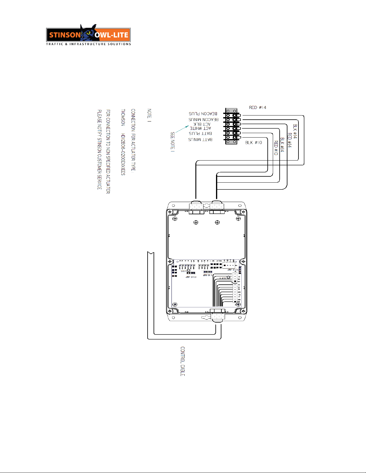
7 April 30, 2019
Figure 2 Terminal Block Wiring
8 April 30, 2019
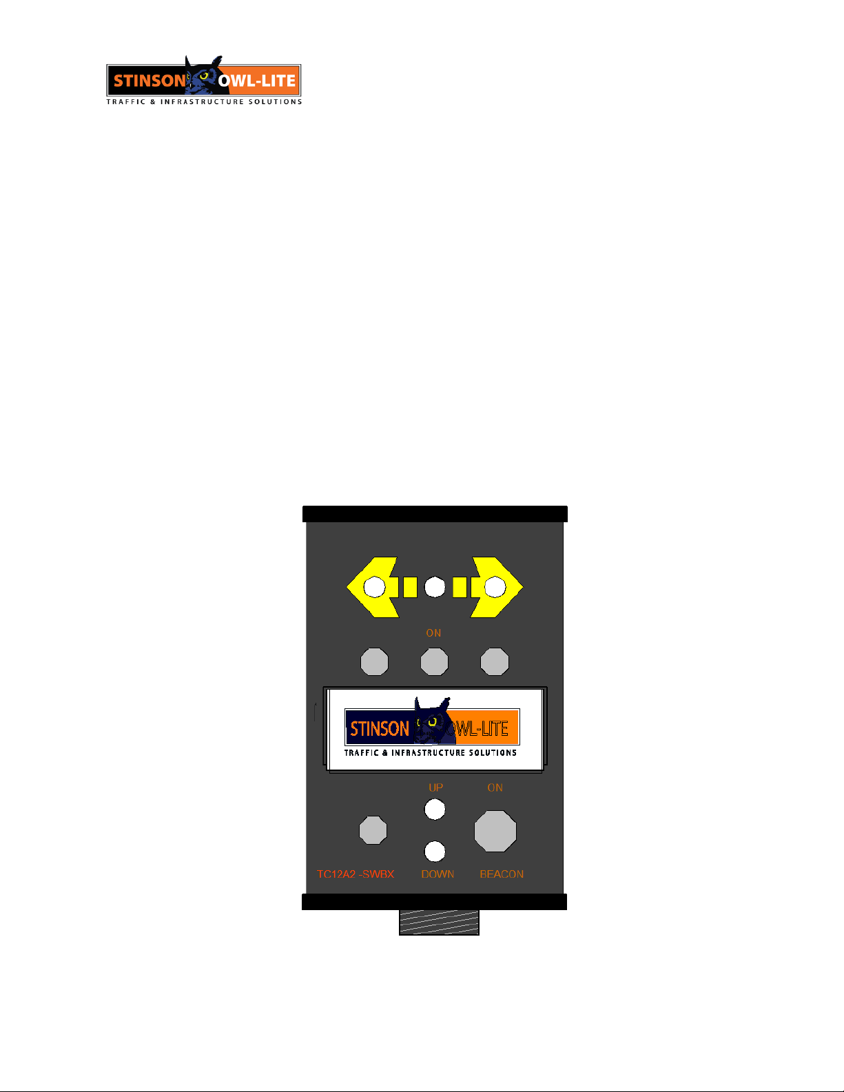
CAB CONTROLLER
The top row of toggle switches control Arrow Board LEDs and actuators. To activate the LEDs
the BAR switch is moved to the ON or to the UP position. The bar row is now activated. The
center LED will flash approximately 40-50 times per second.
The left and right LEDs and actuators can now be deployed by moving the left and right toggle
switches to the UP or ON position.
To de activate the Arrow Board, turn the bar switch to the OFF position. The wings will return to
the extended position and all LEDs on the Arrow Board will turn off.
The switch at the lower left controls raising and lowering the Arrow Board. When the switch is in
the UP position, the arrow board will be in the UP or operating position. The two LEDs beside the
switch indicate the position of the Arrow Board. The top LED (red) is ON when the Arrow Board
is in the UP position. The lower LED is ON (green) when the Arrow Board is in the down position.
There is an option for a beacon switch.
Figure 3 Cab Controller

9 April 30, 2019
ARROW BOARD CONTROLLER
The Arrow Board Controller is located inside the Arrow Board. Signals from the Cab Controller activate
actuator relays and Arrow Board LEDs. The on and off timing of the LEDs is controlled by electronic
circuitry.
A photo sensor is located on the printed circuit board. A clear window located on the rear panel of the
Arrow Board allows light to illuminate the photo cell. During night time operation, the LED intensity is
reduced.
For proper operation of the photo cell, this window should be clear.
The removal and installation of the Arrow Board Controller is straight forward.
OPERATING INSTRUCTIONS
NOTE: When in the vertical position, The Arrow Board is designed for use in moving operations at or
below 40 km/hr.
Prior to operation make sure both the Arrow Board and Cab Controller are connected as shown
in Figure 1
TROUBLE SHOOTING
In the event of failure, please review Table 6 below
The controller is fused to protect against short circuits in the Arrow Board
There are LED indicators that will illuminate under the following Conditions
1. An Lamp (Led) short circuit will open F2. Under these conditions LED 4 will illuminate
indicating fuse F2 has failed or is open.
2. A wing Actuator failure or short circuit will open F3. Under these conditions LED 5 will
illuminate indicating fuse F3 has failed or is open.
3. A short circuit in the up/down actuator circuit will open F1.
In the case of fuse failure, attempt to find short location prior to applying power to controller.
Replace fuses with sizes indicated in figure 6.

10 April 30, 2019
For replacement parts, please see parts list. You can contact our customer service for
assistance in securing a damaged component.
SYMPTON
CAUSE
The Cab Controller does not operate LEDs or
actuators. There is no LED indication on the
Cab Controller
The Arrow Board is not connected to the
Battery or the Battery polarity is reversed.
The Cab Controller does not operate LEDs or
actuators. The UP or DOWN LED correctly
indicates mechanical configuration of the
Arrow Board
Battery Voltage is under 11.5 volts.
Wing Actuators do not function
Check Voltage at Wing Actuator. If the
voltage is present, the Wing Actuator has
failed.
If there is no Actuator voltage, check for open
Actuator fuse (F3 15 AMP). See Fuse
Legend figure 6.
UP/DOWN Actuator Motor does not activate.
Check voltage at UP/DOWN Actuator. If
present UP/DOWN Actuator has failed.
If there is no Actuator voltage, check for open
UP/DOWN fuse (F1 30 Amp) in the Arrow
Board Controller. See fuse legend figure 6.
Bar, Left, Right LEDs are not ON
Check for open fuse (F2 15 Amps). See fuse
legend figure 6.
The Arrow Board LED intensity is low
Probably the solar window at the rear of the
Arrow Board is dirty not allowing the photo
sensor to operate at full intensity.
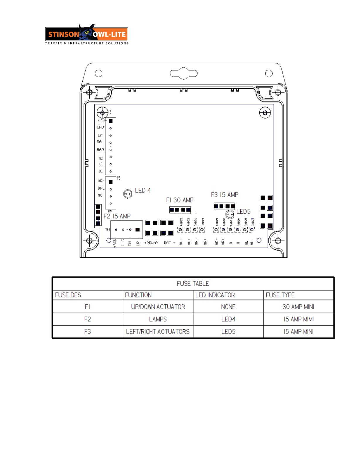
11 April 30, 2019
Table 3 TROUBLE SHOOTING GUIDE
Figure 4Fuse Legend
12 April 30, 2019
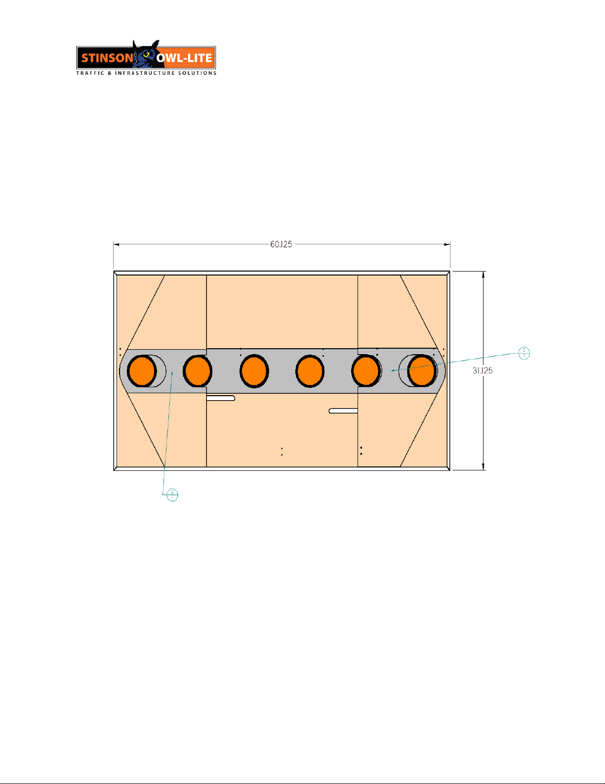
SPECIFICATION
See Stinson Customer Service for specification details 1-800-561-6639
nvironmen
Figure 5 Outline DWG
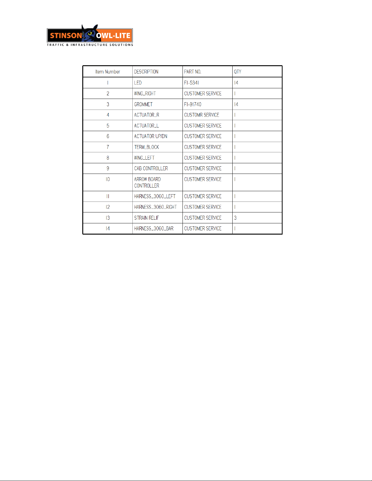
SPARE PARTS
See Stinson Customer Service for spare part service 1-800-561-6639
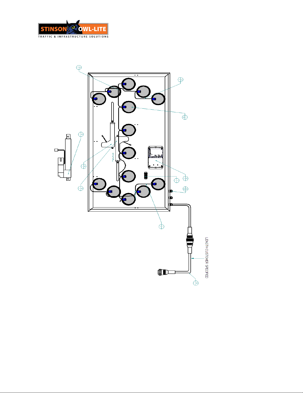
13 April 30, 2019
14 April 30, 2019
Figure 6 BOM

15 April 30, 2019
WARRENTY
WARRANTY POLICY
Thank you for purchasing this quality STINSON EQUIPMENT LIMITED (STINSON) product. We are proud to stand
behind every new STINSON product and this warranty policy is our commitment to you. Please read it carefully.
STINSON warrants that this product will conform to the manufacturer’s standard specifications without defects in
materials and workmanship as outlined below:
Product/ Component
Warranty Period
Mechanical Assembly; (trailers, metal sign
frames, mounting hardware, arrow boards)
-1 year
-Standard coatings excepted
Molded Products; (barrels, cones, markers)
-1 year on plastic integrity
Electrical and Electronic
-1 year
Signs and Sheeted Products
-Sheeting defects, 30 days
Components, sub-assemblies and devices produced by other manufacturers are covered separately and individually
under warranties provided by the specified manufacturer.
There are no warranties expressed or implied which extend these warranty periods. The loss of the product, loss of
time, inconvenience, commercial loss or consequential damages, including cost of any labour, is not covered.
STINSON reserves the right to change the design of the product without assuming any obligation to modify any
product manufactured. This warranty is granted to the original purchaser of the product and is not assignable to any
subsequent purchaser or user. Any leasing or borrowing of these goods or other use beyond normal demonstration of
the same shall be deemed to be use by the original purchaser. The period of this warranty shall commence on the
date of delivery to the first original purchasers. Proof purchase and delivery date may be required when warranty
service is requested.
The sole remedy under this warranty shall be the repair or replacement of parts which have been determined to be
defective after inspection by an approved representative of STINSON. STINSON reserves the right to request the
return of parts replaced under this warranty or in disputable fitness and must be consulted for authorization before
any such return. All defective parts replaced under this warranty shall become property of STINSON. If as claimed
defect cannot be identified or reproduced in service, the purchaser will be held responsible for the costs of
replacement or remanufactured parts. STINSON shall not be responsible for the transportation or mileage costs
associated with repair or replacement of warranted products or parts. The costs of labour associated with corrections
under this warranty shall be reimbursed at a rate deemed reasonable by STINSON if such labour is not performed by
STINSON factory approved personnel. Tampering with the serial number or posted safety and operating instructions
may constitute a breech of this warranty. This warranty shall not extend to any goods or parts which have been
altered, repaired, operated, or maintained outside of approved STINSON procedures or directives. This warranty
does not cover damage resulting from causes beyond the control of STINSON, including without limitation; misuse,
abuse, neglect, or accident; external electrical faults, power surges, or power failure; damage occurring in shipment
or from improper transportation, installation, operation or application; or damage resulting from improper usage or use
of the product with components, accessories or other items not supplied by STINSON. The end-user is responsible
for the selection, use and results obtained from the product.
This warranty applies only to products that have been paid for according to terms under which the product has been
invoiced. Further, the buyer agrees that STINSON will not be required to honour any warranty claim from a customer
whose account at STINSON is not current according to STINSON’s payment terms. This warranty is exclusive and in
lieu of all other warranty, expressed or implied including warranties of merchantability or of fitness for purpose, and
no other warranties which extend beyond the descriptions on the face hereof. The remedies set forth herein and
manufacturer shall not be liable for special, indirect or consequential damages. The obligations of STINSON
hereunder shall not exceed the cost of the equipment or part upon which such liability is based.
Stinson Equipment Ltd. 130 Creditstone Rd. Concord Ontario L4K 1P2

16 April 30, 2019
130 Creditstone Road
Concord Ontario Canada L4K 1P2
Ph ( 905 ) 669-2360 Fax ( 905 ) 669-3537
Company
Address
Phone
Fax
Product
Serial #
Date Purchased
130 Creditstone Road
Concord Ontario Canada L4K 1P2
Ph ( 905 ) 669-2360 Fax ( 905 ) 669-3537
Company
Address
Phone
Fax
Product
Serial #
Date Purchased
Environmental
-40 C – 50 C Opera�onal
-40
Table of contents
Other Stinson Automobile Accessories manuals


