Stockcorner JC-3s User manual

JC-3 manual version 8.1 page 1
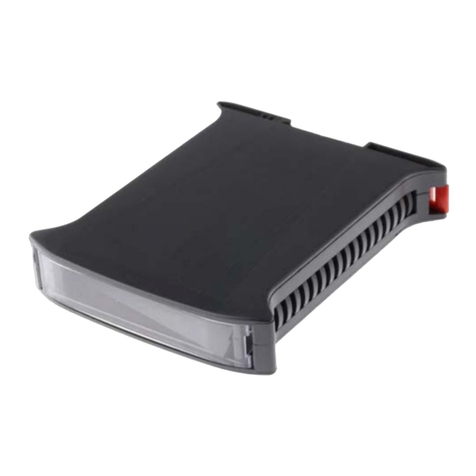
JC-3s MICRO
AUTO ANTENNA COUPLER NEW EDITION
1) 1.8 - 50ΜΗz , 200W SSB FOR ANTENAS 5 M OR LONGER!
2) BETTER PERFORMANCE DUE TO SMALLER CAPAC TOR STEP ( 9pF )
3) D RECT FUNCT ON NG W TH COM , AL NCO , KENWOOD
4) 50 "EEPROM" MEMOR ES – NO BATTERY !!!
NEVER USE THE COUPLER UNTUNED OR “THROUGH”
AND CORRECT THE
SWR USING AN INDOOR ANTENNA TUNER NEAR THE TRANSCEIVER !!!
1. +12 V (BROWN) • +12 VDC POWER SUPPLY (-12 V RETURN V A COAX AL SH ELD !!!)
2. START (GREY) • TUNE COMMAND FROM TRANSCE VER OR CONTROL BOX TO COUPLER
3. KEY (YELLOW) • TX COMMAND FROM COUPLER TO TRANSCE VER OR CONTROL BOX
4. MEMORY (BLACK) • MEMORY CONTROL : +12V NO , 0V YES
GROUND WATCH OUT : -12 V RETURN TO POWER SUPPLY VIA THE COAXIAL SHIELD !!!
MANUAL TUN NG PROCEDURE
Press the BUTTON on the control bo until the led is lit.
Transmit sending a carrier of appro imately 10 to 20 Watts to the coupler until the led goes off.
Adjust power to the final level and transmit! ( Up to 200 W pep SSB )
MEMORY USE
To enable memories we set the switch on the control bo to the Y position. All frequencies we tune, up to 50,
are recorded. When we go to the same frequencies again and perform the tuning procedure ,the coupler is
almost instantly ready to be used. All it has to do is count the incoming signal frequency and use the tuning

JC-3 manual version 8.1 page 2
combination it has done before! ( If it fails because the antenna system has changed, it repeats the tuning
procedure and saves the new combination in the same memory position.)
ERAS NG MEMOR ES
To erase the memories we set the switch on the control bo to the N position and without transmitting we press
the button till the led is lit. Then we set the switch to the up position again. The led is blinking and when it
finishes the memories have been erased!
SPEC F CAT ONS
Circuit type
reversible
L
or
Π
Input capacitance step
(coa ial side)
16pF
Output capacitance step
(antenna side)
9pF
Inductance step
80nΗ
Total capacitance
1800pF
Total inductance
20μΗ
RELAYS
used
Omron
G2R
-
1
and Siemens V23127
Operating frequencies
3
to
50 ΜΗΖ
Ma imum power for antennas
> 15
μ
.
200W SSB ( 50W AM )
Minimum antenna length
for
200 W SSB
10μ.
3
to
50 ΜΗΖ
Minimum antenna length for
50 W
ΑΜ
10μ.
6
to
50 ΜΗΖ)
Recommended tuning power
10
–
20 W (carrier)
Typical tuning time
1
–
3 sec.
Ma imum tuning time
6 sec.
Supply voltage limits
12.5
–
16 V
Ma imum supply current
0.7 A
Typical
VSWR (tuner
input
)
< 1.1 : 1
Ma imum
VSWR (
tuner
input
)
< 1.
9
: 1
Protection
(
NOT FOR LIGHTNING STRIKE
! )
Static discharge
D
imentions
(
without
mounting bracket
)
COUPLER
19 10.5 9.5 cm
CONTROL BOX
Connection with
Power supply:
RED = +12 V
BLACK= -12V
BROWN
+12V
–12 V returns to supply via coa ial shield !
GREY
START
Led
remains
lit for 10 sec when
start
button is
pushed . (Send carrier to perform tuning…….)
YELLOW
KEY
(……..coupler is tuned when LED is off )
BLACK
MEMORY
ENABLE/DISABLE
(
CTRL BOX :
Y
-
> EN
/ N
-
> DIS
)

JC-3 manual version 8.1 page 3
TRANSCE VER – COUPLER COMMUN CAT ON CABLE
DISTANCE
2
-
20
m
.
DIAMETER
0.50
mm
20
-
35
m
.
0.75
mm
35
-
50
m
.
1.00
mm
D RECT CONNECT ON BETWEEN COUPLER AND TRANSCE VER
YAESU
ALINCO
ICOM
KENWOOD
YAESU DOES NOT HAVE
START - KEY LOGIC.
OPERATION IS ONLY
POSSIBLE USING THE
CONTROL BOX !!!
ΟΟΟΟΟ
Ο Ο Ο Ο
Ο
Ο
KEY
Ο
GND
GND
+12V
KEY
SRT
KEY
SRT
+12V
GND
Ο
SRT
Ο
+12V
*We connect +12V , START and KEY terminals with the proper connector behind the transcei er.
(-12 V does not need to be connected to the coupler since it returns to the power supply ia coaxial shield.)
Transcei er’s MENU must be programmed for external coupler operation, if needed.
ATTENTION: If you use the control box with a separately power supply than the power supply of your radio then
you MUST connect the “-“ of the 12 tuner power supply to the GROUND connection of the radio. You can do this
with a separate single earth wire.
Always a oid ½ wa e length wires. Better is to make it just a little longer. So better 12 meter than 10 meter long
wire.
USE RUBBER TAPE TO ISOLATE YOUR CONNECTORS FROM WATER AND RAIN
(Lik vulcaniz d T lco tap and so on)
The earth connection and wires are ery important. Just some radials on the ground is not good enough! The
counterpoise must be as close to the tuner outside as possible for the best performance.
Do not open the JC-3 tuner box for maintenance. It has no parts for service inside or any ad ustment or
switches.
The box is sealed which you have to seal again if you open the tuner anyway.
We recommend to make precautions that full rain does not come direct on the tuner box

JC-3 manual version 8.1 page 4
Mobile HF radio connected with tuner and 1 power supply
Mobile HF radio & tuner connected with 2 separately power supplies

JC-3 manual version 8.1 page 5
HF Base radio connected with tuner and separately power supply
Tuner connected directly to a radio. READ manual (so control box not needed in this setup)

JC-3 manual version 8.1 page 6
Some antenna e amples. There is no “best” solution. It all depends on your interest, length of wires and space
around the antenna.

JC-3 manual version 8.1 page 7
www.stockcorner.nl
email: info@stockcorner.nl
Table of contents

