STOLZENBERG TwinSweep 900E User manual

htttp://www.stolzenberg.de
!
Instruction Manual
(Translation of the Original Version)
EN
TwinSweep 900E
2021-01-11

2

This operating manual contains instructions for using the
sweeper.
Carefully keep the operating manual so that you can refer to it
later.
Our products are being continuously improved. Design changes
after going to print may therefore not be considered. If you have
any questions, please contact our Service department (for
contact details, see page 17).
Carefully study the operating manual and the general
safety instructions before you unpack the machine
any further or undertake first start up.
The operating manual is to be read attentively and followed by
any person that operates the sweeper.
3
1.1 CONTENTS
1 CONTENTS / CONTENTS / GENERAL
1.
Contents, General
….3
1.1
Contents
.…3
1.2
Proper Use
….3
1.3
EC Conformity Declaraon
.…3
1.4
Rang Plate
.…3
1.5
Explanaon of Symbols
.…4
2.
Construcon, Funcon, Technical Data
.…4
2.1
Packing Contents
.…4
2.2
Funcon
.…4
2.3
Operang and Funconal Components
.…4
2.4
Technical Data
.…5
3.
Safety
.…6
3.1
Safety Instrucons
.…6
3.2
Symbols in the Operang Manual
.…6
3.3
Symbols on the Sweeper
.…6
3.4
Safety Equipment
.…6
4.
Seng Up/Before Start Up/Start Up/Transport
....7
4.1
Unpacking the Sweeper
.…7
4.2
Waste Disposal / Recycling
.…7
4.3
Adjusng the Transport Bar
.…7
4.4
Fing the Side Brushes
.…7
4.5
Opening the Front Panel
.…8
4.6
Closing the Front Panel
.…8
4.7
Before Start Up/Transport Weight
.…8
4.8
Baeries / Charger
.…8/9
4.8.1
Fing Baeries and Connecng
.…9
4.8.2
Baery Connecon Diagram
.…9
4.8.3
Charging Baeries / Baery Charge Indicator (LBF)
.…10
4.8.4
Charger
.…10
4.8.5
Removing Baeries
.…10
4.9
Start Up
.…11
5.
Operaon
.…11
5.1
Starng Sweeper
.…11
5.2
Driving Sweeper
.…11
5.3
Sweeping Operaon with Side Brushes, Roller Brush
and Fan
.…11
5.4
Switching Off Sweeper
.…12
5.5
Transporng the Machine
.…12
5.6
Cleaning the Dust Filter
.…12
5.7
Emptying the Dirt -
Hopper
.…12
6.
Troubleshoong
….
13
7.
Care and Maintenance (Minor Repairs)
.…12/13
7.1
General Cleaning
.…14
7.2
Changing / Cleaning the Filter
.…14
7.3
Inserng the Filter
.…15
7.4
Tipping the Sweeper
.…15
7.5
Changing the
Roller Brush
.…15
7.6
Seng Roller Brush Clearance
.…16
7.7
Changing the Side
Brushes
.…16
7.8
Seng the Side Brushes
.…16
7.9
Changing the Front Sealing Rubber
.…16
7.10
Changing the Side Sealing Rubber
.…17
7.11
Seng / Replacing the Drive Bowden Cable
.…17
7.12
Seng / Replacing the Side Brush Bowden Cable
.…17
7.13
Important Spare Parts and Consumables / Contact
.…17
7.14
Contact Data
.…18
7.15
Maintenance Work / Maintenance Table
.…18
8
Shut Down, Dismantling, Disposal
.…19
9
Circuit Diagram
.…20

Only use the sweeper according to the specifications in this
operating manual.
The sweeper is only intended for sweeping hard standing areas
(e.g.: car parks, pavements, warehouses). The sweeping
environment must not be wet.
The sweeper must only be operated by reliable, instructed
personnel.
Prevent it from being used by children, young people and other
unauthorised persons, e.g. by removing the key after use.
Any other usage beyond this is deemed to be improper use (see
“Safety Instructions”, chapter 3). The manufacturer is not liable
for any damage resulting from this.
The user is solely responsible for the risk.
Proper use also includes following the operating manual, the
safety instructions and keeping to the servicing and
maintenance specifications.
Only operate in expressly assigned routes and places.
Observe the maximum climbing ability specified in the technical
data and maximum possible slope inclination for operating
across slopes. Due to an abrupt change of direction, particularly
on slopes, the sweeper may tip. Adapt your operating manner
and speed to the conditions.
Follow the instructions on suitable ground (asphalt, screed,
industrial floors, concrete, paving stones etc.)
The rating plate is attached on the top of the frame below
the front panel.
1.4 RATING PLATE
1.4 EG KONFORMITÄTSERKLÄRUNG
1.2 PROPER USE
1.3 EC DECLARATION OF CONFORMITY
4
1.5 EXPLANATION OF SYMBOLS
DANGER! ......indicates a possibly dangerous situation
that can cause death or serious injuries.
CAUTION! ......indicates a possibly dangerous situation
that can cause minor injuries.
INSTRUCTION .....indicates important information.
WARNING ...indicates a possibly dangerous situation
that may cause material damage.
Stolzenberg GmbH & Co. KG
Hamburger Str. 15-17
49124 Georgsmarienhütte
Germany
www.stolzenberg.de Made in Germany 2020
MODEL:
SERIAL NUMBER:
PROTECTION:
GVW:
TwinSweep 900E PRO
XXXXXXXXX
IPX3
165 kg
max. 2%
TwinSweep 900E
The TwinSweep 900E is a battery-operated, hand-driven
pedestrian-controlled vacuum sweeper fitted with the tandem
roller system (TRS).
The TRS allows large sweeping materials to be swept up without
difficulty. The sweeper has a powerful vacuum function.
2 CONSTRUCTION, FUNCTION, TECHNICAL DATA
In the tandem roller system (TRS), sweeping materials are first
conveyed by means of the side brush (a) from the corners and
edges of the sweeping area into the centre of the machine and
therefore towards the two counter-rotating roller brush (b).
From this, the sweeping material is taken up and conveyed into
the dirt-hopper (c) situated at the back.
The dust stirred up by the sweeping process is vacuumed up by
a vacuuming system (fan) (d), filtered by flat-pleat filter (e) and
thus separated from the clean air.
Electro-mechanical filter cleaning (f) removes the dust caked
onto the flat-pleat filter and allows this to drop into the
dirt-hopper.
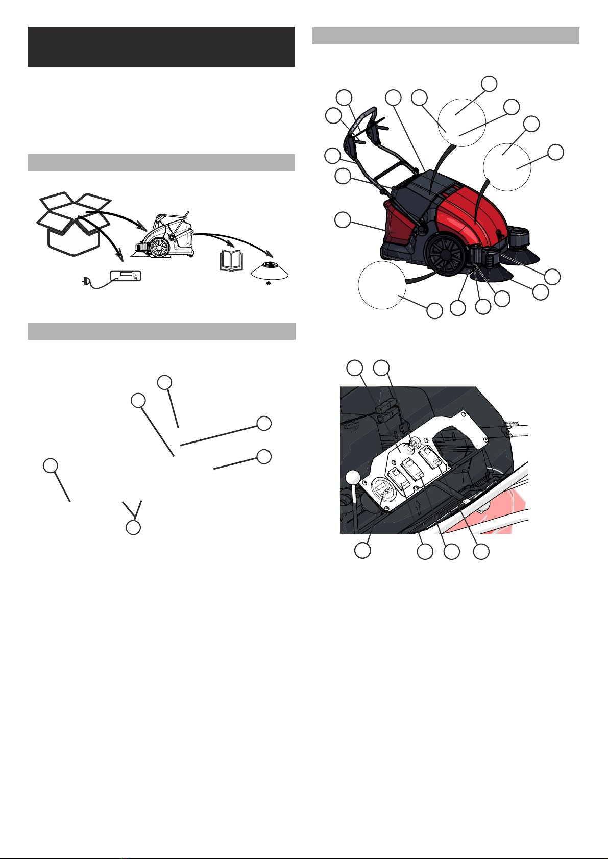
2.3 OPERATING AND FUNCTIONAL COMPONENTS
Overview:
2.2 FUNCTION
a
b
c
d
f
e
111
11
2
11
5
11
4
11
6
117
11
10
11
11
11
8
11
3
11
9
11
12
11
13
11
11121117 15 16 14
11
18
11
19
11
20
12
* The version of the machine may differ from the illustration
* The version (Basic, Plus or Pro) of the
machine may differ from the illustration
2.1 PACKAGING CONTENTS
TS900E
LED
* External charger only for Basic version
** The machine may differ from the illustration
**
*
13 Key Switch (Main Switch)
14 Side Brush Switch
15 Roller Brush Switch
16 Fan/Shaker Selector (Only Pro)
17 Charge Indicator/Hours Meter
18 Battery/Batteries (Basic 1x50Ah /
Plus 1x75 Ah / Pro 2x50Ah)
19 Charger on Board
(only Plus and Pro, Basic External Charger)
20 LED Front Light (only Pro)
21 Filter cover
22 Side Sealing Rubber
23 Front Sealing
1 dirt-hopper
2 Shaker rod (Basic + Plus)
3 filter cleaning
Mechanical (Basic + Plus)
electrical “by touch of a button” (Pro)
4 Transport Bar
5 Transport Lever
6 Brush Selector
7 Roller Brush
8 Flat-Pleat Filter
9 Control Panel
10 Side Brushes
11 Vacuuming System (Fan)
5
21
11121122
11
12
11
23

6
2.4 TECHNICAL DATA
Basic Plus Pro
Length x width x height (pusing handle unfolded) max mm
Length x width x heigth (without pusing handle) mm
Length x width x height (pusing handle folded in) mm
Weight (without batteries) kg 83 90 94
Weigth (with batteries) kg 98 114 124
Permissible overal weight kg
Driving and sweeping speed km/h
Climbing capability (max.) %
Incline (max.) %
Center-brush length mm
Center-brush diameter mm
Side-broom diameter mm
Theoretical sweeping performance (at 4 km/h) m2/h 4400
Effective sweeping performance (70%) m2/h 3080
Sweeping width with folded-out side-brooms (mm) mm 1100
Sweeping width with folded-in side-brooms (mm) mm
Sweeping width - center brush mm
Dirt-hopper size l
Permissible maximum payload dirt - hopper kg
IPX-protection type --
Type -- 12V 50Ah (C20) AGM 12V 75Ah (C20) AGM 2x 12V 50Ah (C20) AGM
Capacity Ah 50 (20h) 75 (20h) 100 (20h)
Weigth kg 15,1 24,2 30,2
Charging time for fully discharged battery(80%) h 4 6 8
Run time up to h 2,5 2 2,5
Charger -- External On board On board
Mains voltage V~
Output voltage V
Charging current A
Mains frequency Hz
Central relay A
Circuit breaker forward traction A -- 25 25
Circuit breaker center-brush A 20 20 20
Circuit breaker side-broom A 10 10 10
Circuit breaker filter-shaker A -- -- 10
Circuit breaker suction system A 15 15 15
Deep discharge protection --
Filter cleaning electrical
Filter area m²
Filter class --
Operating tempreture °C
Chraging tempreture °C
Sound pressure Level L
pA dB(A)
Uncertainty KWA
Sound power level L
WA + Uncertainty KWA dB(A)
Vibration m/s2
1085x820x790
Technical data
Machine data
1085x820x1200
1085x820x710
500
165
4
2
2
500
195
354
3600
2520
--
900
Electrical fuses
75
40
IPX 3
Battery
Charger
100-240V AC
12
10
50/60
62
70
Battery indicator (LBF)
Filter- und vacuum-system
mechanical
2,5
M
Working conditions
-15 bis +40
-15 bis +40
Values according to EN 60335-2-72
3
83
<2,5
dB

3 USAGE
INTRODUCTION / PROPER
3 USAGE
INTRODUCTION / PROPER
3 USAGE
INTRODUCTION / PROPER
3 USAGE
INTRODUCTION / PROPER
3 USAGE
INTRODUCTION / PROPER
3 USAGE
INTRODUCTION / PROPER
Switching
Driving Switching on
Switching
Driving Switching on
3 • To avoid damage to health, smoking, eating and drinking
in the area of the battery charging station is to be
avoided.
• The battery must only be charged with the front panel open
and secured by the cover holder.
• Ensure safe and environmentally-friendly disposal of
operating and auxiliary materials, as well as replacement
parts, particularly batteries!
Safety Instructions for Care and Maintenance
• Before cleaning and maintaining the equipment,
replacing parts or changing to a different function, the
equipment is to be switched off
and the ignition key is to be pulled out.
• Spare parts must correspond to the requirements laid down
by the manufacturer. This is always guaranteed for original
spare parts.
• Accessories and spare parts must only be installed by an
authorised customer service department.
• For work on the electrical system, the battery is to be
disconnected.
• The equipment must not be cleaned
with a hosepipe or high-pressure water jet (risk of short-
circuits or other damage).
• Repairs must only be made by the permitted customer
service centres or by experts in this field familiar with all the
relevant safety regulations.
• Follow the safety review according to the locally -applicable
regulations for mobile industrial equipment.
• Always wear suitable gloves when working on the
equipment.
SAFETY
3.1 SAFETY INSTRUCTIONS
As well as the operating manual and the binding regulations
for accident prevention applicable in the country of usage and
at the place where it is deployed, recognised rules for safety
and expert working, and environmental protection, are also to
be followed.
Safety Instructions for Operation
• The machine is to be inspected before usage for its perfect
condition and operational safety. If it is not in perfect
condition, it must not be used.
• In particular, have any errors that may affect safety
rectified immediately.
• Operating the machine in buildings at risk of
explosion is prohibited.
• Sweeping up of flammable, toxic or explosive materials and
combustible gases or undiluted acids and solvents, burning or
smouldering objects is prohibited.
• The device is not suitable for accepting fluids, ropes, twines,
wires or similar items.
• Only use the machine with the dirt-hopper inserted
to prevent injuries due to parts being projected.
• Do not make any alterations or additions to the machine
without the approval of the manufacturer.
• Persons (including children) who, due to their
physical, sensory or mental capacities or their inexperience or
lack of knowledge, are not capable of using the machine safely
must not use this machine without the supervision or
instruction of a responsible person. Children must be
supervised to ensure that they do not play with the machine.
• Caution: Loose items of clothing may be drawn into
rotating parts and cause serious or fatal injuries.
• Transporting loads with the sweeper is not permitted.
• Observe the maximum climbing ability specified in the
technical data and maximum possible slope inclination for
operating across slopes. The equipment may tip, particularly
on slopes. Adapt your operating manner and speed to the
conditions.
• The machine is not permitted for use on roads.
• Suitable, non-slip footwear is to be worn to avoid accidents.
Safety Instructions on Batteries
• The operating instructions of the battery manufacturer for
their product and the specifications of the legislator on
handling batteries are to be followed.
• Charge flat batteries directly after usage and only keep in
well-ventilated rooms.
• Keep away from naked flames and electrical sparks in
the charging area, as a highly-explosive gas mixture
can be produced when charging batteries.
• Note that the batteries may be filled with battery acid.
• Always keep batteries clean and dry to avoid
leakage currents. Never short circuit the battery
terminals.
7
WARNING! CAUTION! DANGER! THE
INSTRUCTIONS DESCRIBED MUST BE
FOLLOWED
WEAR BREATHING PROTECTION!
WEAR PROTECTIVE GOGGLES!
WEAR GLOVES!
FOLLOW THE INSTRUCTION!
3.2 SYMBOLS IN THE OPERATING MANUAL
3.3 SYMBOLS ON THE SWEEPER
WARNING! CAUTION! DANGER! THE
INSTRUCTIONS DESCRIBED MUST BE
FOLLOWED!
FOLLOW THE OPERATING INSTRUCTIONS!
4.3 ADJUSTING THE TRANSPORT BAR
HINWEIS! Bitte befragen Sie zur Entsorgung des Gerätes Ihren Lieferanten.
3.4 SAFETY EQUIPMENT
8
HINWEIS! Bitte befragen Sie zur Entsorgung des Gerätes Ihren Lieferanten.
4 .5 OPENING EQUIPMENT PANEL
4 .5 OPENING EQUIPMENT PANEL
4 .5 OPENING EQUIPMENT PANEL
- Safety equipment is to be inspected for functioning before
starting work.
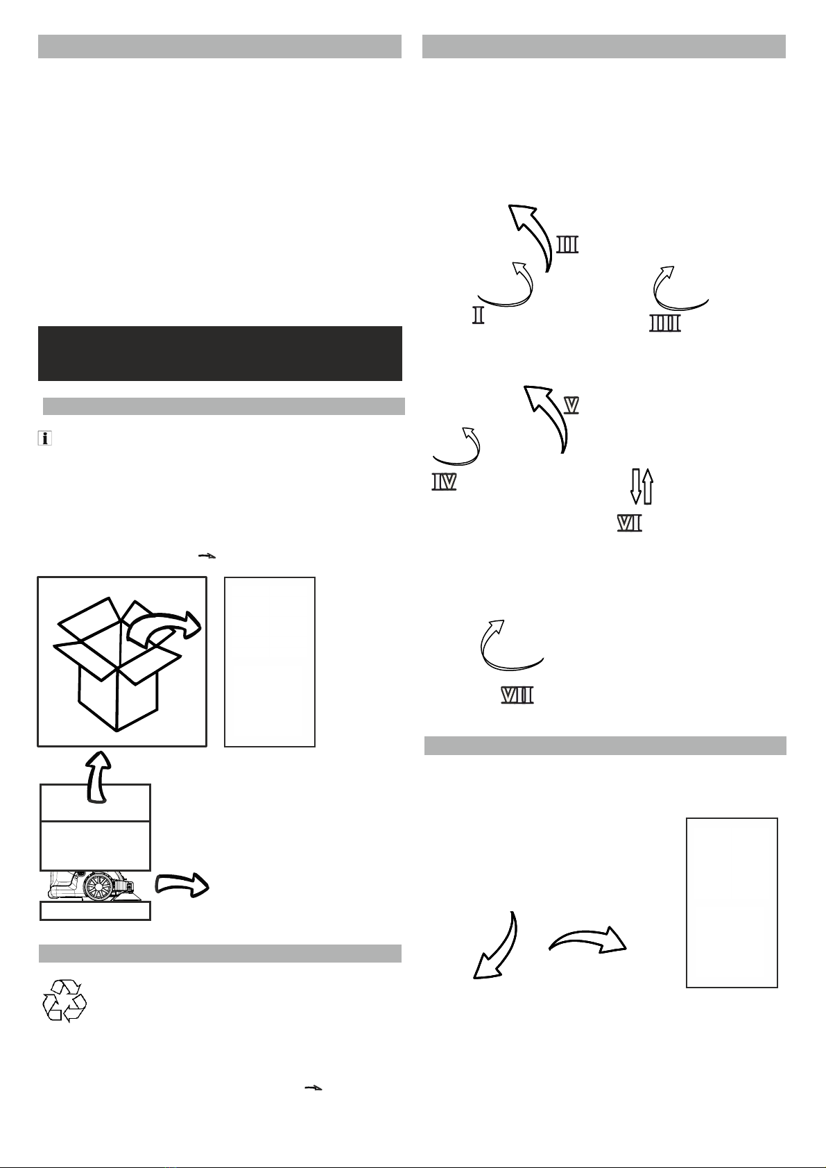
• Undo star screws of the raster fastening on the frame (I)
• Fold out lower transport bar (II)
• Retighten star screws (III)
• Undo star screws on the upper transport bar (IV)
• Set out the upper transport bar
• Adjust the transport bar for the operator using the star
screws (III + IV + VI)
• Tighten all star screws (VII)
- Only allow the sweeper to be switched on if the following
conditions are met:
a) The start key is in the ON position.
b) The filter box is closed
c) The dirt-hopper is closed .
The power supply to the sweeper is interrupted when:
a) The start key is switched to the OFF position
b) The filter box is open
c) The dirt-hopper is open
The safety equipment attached to the machine must not be
bypassed or put out of operation.
4.1 UNPACKING THE SWEEPER
- Remove the box.
- Remove wooden blocks for securing the wheels.
- Stop the transport bar in the desired position using the star
handle.
See also: PACKING CONTENTS Chapter 2.1
4.4 FITTING THE SIDE BRUSHES
Put the side brushes onto the take-up of the driver (Fig. 2) and
screw tight with the wing bolts (includes: washer, serrated lock
washer, O-ring and wing bolt - Fig. 3).
Fig. 1
(Initial
Assembly)
4.2 WASTE DISPOSAL / RECYCLING
Recycling packaging materials. Do not dispose of
packaging materials in normal waste but forward for
reprocessing.
For the disposal of all packaging materials, the disposal
conditions specific for the location are applicable.
See also: Putting Out of Operation / Recycling
Chapter 8
Fig. 2 Fig. 3 Fig. 4
4 STTING UP/ B S U /
O T
Instruction Look out for damage in transit and if there is
any, indicate this to your specialist dealer without delay.

9
4 .5 OPENING EQUIPMENT PANEL v• Connect the terminal (red cable) to the plus pole of the
battery.
• Push the side brushes on the driver and screw
tightly.
• Close the equipment panel and the dirt-hopper
• Stop the transport bar using the star handle into the
desired position.
4.8 BATTERIES / CHARGER
Safety Instructions on Batteries
You must note the followi ng warning instructions for handling
batteries:
4.5 OPENING THE FRONT PANEL
The front panel is unlocked with a panel
key (rotate clockwise).
Remove the key and open the front panel
and pull to its highest position,
the panel will engage automatically.
To do this, you must read the General Safety Instructions,
particularly the Battery Warning Instructions Chapter 3!
Recommended Batteries
Please use original spare parts and contact Customer Services.
4.8.1 FITTING BATTERIES AND CONNECTING
4.6 CLOSING THE FRONT PANEL
Raise the front panel slightly to close it and push the backplate
(holds the equipment panel) back slightly and close. The
equipment panel engages automatically.
There is a risk of crushing. When closing remove all
body parts from the danger area.
• Open front panel
• Undo the charger holder (star
handle) and fold upwards.
• Place batteries onto the
mounting plate (2).
• Connect any connection
cable of the battery.
• Secure batteries with the
relevant holding strap (1).
* The battery/ies may differ
from the illustration
4.7 B S U T W
• The terminal
(red cable) is to be attached to the plus pole (+) of the battery.
• Attach the connection table (short red cable only for 2
batteries) respectively to the plus pole (+).
• Terminal to the minus pole (-)
• Only use batteries with pole cover!
INSTRUCTION Attach the batteries according to the
specification
See (Fig. 1-2 - CONNECTING BATTERIES Chapter 4.8.3)
INSTRUCTION Charge the batteries before putting the
equipment into operation! (Ch. 4.8.3 +4.8.4)
INSTRUCTION Charge the battery fully!
4.8.2 BATTERY CONNECTIONDIAGRAM
DANGER!
Risk of injury and/or damage! Take care of the weight of the
equipment when charging!
CAUTION! Only operate with the front panel and
dirt-hopper closed.
CAUTION! Charge the battery fully!
• Make sure you are satisfied that the machine has been
supplied undamaged and complete.
Fig. 1: Battery Version Basic + Plus
See also UNPACKING THE SWEEPER Chapter 4.1
• If you have any complaints, contact your specialist dealer
or our Service department.
• Read the SAFETY INSTRUCTIONS Chapter 3.1
• Read the operating manual of the charger provided. Take
note of the warning instructions for the battery! Fig. 2: Batteries - Pro Version
TRANSPORT WEIGHT
Version BASIC PLUS PRO
WEIGHT empty 83 90 94
WEIGHT with batteries 98 114 124
WARNING! CAUTION! DANGER! THE
DESCRIBED INSTRUCTIONS MUST BE
FOLLOWED!
FOLLOW THE OPERATING MANUAL OF THE
SWEEPER!
WARNING! - WEAR GLOVES WHEN WORKING IN THE
AREA OF THE BATTERY TO AVOID INJURIES
WARNING! CAUTION! DANGER! THE
INSTRUCTIONS DESCRIBED MUST BE
FOLLOWED!
FOLLOW THE INSTRUCTIONS ON THE
BATTERY, IN THE USER INSTRUCTIONS FOR
THE BATTERY AND THE OPERATING
INSTRUCTIONS.
11
1
11
2
10
After charging, unplug the on-board
• charging unit mains cable.
• Unwind the mains cable from the charger cable bracket.
• Close the equipment panel.
Charging external charger
• Open the equipment panel
• Plug in the charger charging cable into the
charging terminal of the sweeper.
• Plug the mains plug of the charger into the socket and
switch on the charger.
After charging, unplug the external charger
• Switch o ffthe charger and disconnect from the mains.
• charging cable on the equipment.
• Close the equipment panel.
4.8.3 CHARGING BATTERIES
DANGER Risk of injury, the charger must only be
put into operation if the mains cable is
not damaged. A damaged mains cable is to be replaced
without delay by the manufacturer, Customer Services or
a qualified person.
DANGER Danger of electric shock. Follow
mains and use the correct fuse. Only user charger in
dry rooms with sufficient (i.e. open front panel)
ventilation. Observe charging times.
DANGER Risk of injury! Follow the
safety instructions when handling batteries. Follow usage
instructions of the charger manufacturer.
Battery charge indicator
INSTRUCTION The equipment is fitted as standard with
maintenance-free batteries.
4.8.5 REMOVING BATTERIES
• Open front panel. (See Chapter 4)
• Disconnect any charging plug
•
•
•
Disconnect terminal from minus pole (-
Disconnect terminal from plus pole (+).
Unscrew battery connection cable.
Undo the charger holder (star handle)
and fold upwards.
Undo holding strap.
Remove battery.
Dispose of used batteries according to
•
4.8.4 CHARGER
INSTRUCTION Read the operating manual of the charger
manufacturer.
INSTRUCTION Batteries must only be charged at room
temperature.
Charging on-board charger
• Open the equipment panel
• Plug the mains plug of the charger into the socket.
INSTRUCTION The charger is electronically controlled and
stops charging automatically. All functions of the sweeper are
automatically interrupted during charging.
-
If the battery or batteries is/are charged, the yellow light of
the charger is lit.
-
The battery is fully charged if the light of the
charger is lit green.
•
•
•
the applicable provisions (see Ch. 3 Environmental
Protection).
Operational lit yellow
Charge battery lit red
Protection against deep discharge flashes (equipment shuts down)

11
Switching on
4.9 S U
General Instructions
DANGER! Risk of injury! Switch off equipment before
removing the dirt-hopper.
CAUTION! Only operate with the front
bonnet and dirt-hopper closed.
INSTRUCTION
5.2 DRIVING SWEEPER
• Pull drive lever The sweeper moves forwards.
The drive speed is according to the lever setting
steplessly controllable.
• Releasing the drive lever stops the sweeper.
• The sweeper may also be pushed without the drive.
Running Over Obstacles
• Fixed obstacles up to a height of 45mm may be run over
slowly and carefully.
• Obstacles must always be run over with a ramp to protect
the machine.
5.3 S O - W S B, R B A F
CAUTION!
Sweeping material that is too large or non-uniform may be
disposed of via the raised filter lid directly into the
dirt-hopper.
Risk of dust! Wait 5-10 seconds before opening the filter
cover.
CAUTION!
Do not sweep up any straps, wires or similar as this may cause
damage to the sweeping mechanism.
INSTRUCTION
The fan should be switched on in general.
As required:
• Lower the side brushes accordingly (operate pedal)
• Side brush switch in Pos. I (ON), Pos.0 (OFF)
• Roller brush switch in Pos. I (ON), Pos.0 (OFF)
• Shaker in Pos. I (ON), Pos.0 (OFF)
• Operate selector
(side brushes swivel out to the side)
MUST BE FOLLOWED! B S U , .
• Make sure you are satisfied that the machine has been
supplied undamaged and complete. See BOX CONTENTS, chapter 2.1
See UNPACKING, chapter 4.1
• If you have any complaints, contact your specialist dealer
or our Service department.
MUST BE FOLLOWED!
You must only carry out the work described in this chapter if
you have completely read and understood the operating
manual, particularly Chapter 1-4.
INSTRUCTION Safety equipment is to be inspected for
functioning before starting work.
See also Safety, chapter 3
DANGER! If the equipment is used for extended
circulatory disorders in your hands due to vibrations
may be caused. A generally-applicable usage time cannot
be specified, as this depends on several influencing
factors: These include a firm grip, low ambient
temperature and personal disposition. It is recommended
that you take regular breaks, and put the driving bar in an
optimum position.
INSTRUCTION
Please adjust driving speed to the conditions (different
ground surface, type and amount of sweeping material), to
obtain a good sweeping result.
INSTRUCTION
When in operation, the dust filter must be cleaned at
regular intervals and as required.
INSTRUCTION
When in operation, the dirt-hopper must be
emptied at regular intervals and as required.
BASIC Version
Pos I (ON)
Pos 0 (OFF)
Pos I (ON)
Pos 0 (OFF)
PLUS Version
Pos I (ON)
Pos 0 (OFF)
Pos I (ON)
Pos 0 (OFF)
Pos I (ON)
Pos 0 (OFF)
See also
See also
C D F , C .
E D-H, , ..
5.1 S S
• Put the key into the key switch and turn it clockwise to
the “ON” position. The drive motor starts.
PRO Version
Pos I (FAN ON)
Pos I (ON)
Pos 0 (OFF)
Pos 0 (Fan OFF)
Pos I (ON)
Pos 0 (OFF)
Pos II (Operate shaker)
5 OPERATION (USAGE AND OPERATION)

12
5.4
SWITCHING OFF SWEEPER
• Set down the machine on a level, dry and
protected ground surface.
• Switch off the roller brush, side brushes and
vacuuming system.
• Put the key into the “OFF” position
(anticlockwise) and pull out.
• Fold in the side brushes.
• Raise the side brushes with the pedal.
• When setting down, the machine has to be secured
against inadvertent movement.
5.6 CLEANING THE DUST FILTER
CAUTION!
Risk of crushing when closing
the filter box.
5.5 TRANSPORTING THE MACHINE
DANGER! Risk of crushing! Observe the weight of the
machine!
INSTRUCTION!
Do not kink any Bowden
cables!
• Switch off sweeper and pull out the ignition key.
• Fasten the wheels of the machine with chocks.
• Fasten the machine with tensioning belts or ropes.
• While transporting in vehicles or trailers, the
machine has to be secured, according to the
relevant applicable guidelines, against sliding and
tipping.
• Two fastening areas for belts:
a) Machine vertically fastened (fastened to
the floor as illustrated)
b) Machine horizontally fastened (fastened to
the wall as illustrated)
Instruction Ensure that the dirt-hopper has been
inserted.
• When using the electric shaker (I), operate it
for approximately 15-20 seconds.
• When using the mechanical shaker, operate the shaking rod on
the ball knob several times (5-10 times)
(alternately to the left and right)
Instruction It is recommended waiting 5-10 seconds until the
fine dust has settled before emptying the dirt-hopper.
5.7
E D-H
DANGER!
Risk of injury! Switch off equipment before
removing the dirt - hopper.
Instruction The maximum permitted load (sweeping
material) of the dirt-hopper is 40 kg.
Instruction The dirt-hopper must be emptied at
regular intervals to enable perfect sweeping.
• Clean the dust filter regularly.
• Remove the dirt-hopper from the
sweeper using the handle on the top.
• Empty the dirt-hopper thoroughly after
finishing sweeping work.
• Empty the dirt-hopper into a suitable
container.
• Push the dirt-hopper back into the machine.
a) b)
CAUTION! Risk of crushing when closing
the dirt-hopper!

Help for faults
Fault Possible cause Remedy
Device does not start
Battery state ≤20% ►Charge battery
Battery cable not correctly connected or loose ►Check cabling of the batteries and connect correctly
Safety switch in the filter cover not operated ►Close filter cover and insert dirt-hopper correctly.
Overload or fault with the main relay ►Check and replace main relay
Cause unclear
►Notify your dealer or customer services
Drive motor running, but device
is not operating
Bowden cable of the traction drive has extended or is not functioning ►Check and adjust Bowden cable of the drive
Lack of power transmission of the drive belt ►Check and adjust drive belt of the drive
Cause unclear
►Notify your dealer or customer services
Device stops on a slope when
operating
Slope >2% ►Travel on a route with smaller slope
Bowden cable has extended and the power transmission of the
drive belt is no longer sufficient
►Check and adjust Bowden cable of the drive
Lack of power transmission of the drive belt ►Check the drive belt of the drive
Permitted total weight of the machine exceeded by full
dirt-hopper.
►Empty dirt-hopper.
Main relay or relay for the drive has been overloaded and is/are
faulty
►Check relay for the drive
Cause unclear
►Notify your dealer or customer services
Roller brushes are not running
Straps, large packaging residues etc. have been swept up
►Turn key switch to "0" (switch off sweeper). Check roller brushes
for jammed or picked-up objects such as, for example, straps,
cables etc., remove them and check the roller brush for damage
and free running.
Functional fault of the toothed belt or gear wheels (e.g. toothed
belt has come off)
►Check toothed belt and gear wheels
Roller brush motor overloaded (check brushes for free running, as
appropriate)
►Check and replace relay of the roller brush motor
Cause unclear
►Notify your dealer or customer services
Bad sweeping in the edge region
Side brushes worn ►Check for wear, readjust as required or replace the side
brushes
Side brushes have not lowered ►Lower the side brushes
Functioning of the side sealing rubber restricted by wear, a fault
or similar.
►Replace side sealing rubbers as appropriate
Cause unclear
►Notify your dealer or customer services
Swivelling the brushes in and out
not working
Bowden cable has extended or is not functioning ►Check and adjust Bowden cable of the side brushes
Leg spring in the side brush not working (side brush does not
swivel out)
►Check leg springs in the side brushes for damage and correct
seating and replace as necessary
Side brush jammed by dirt Clean side brush suspension
Cause unclear
►Notify your dealer or customer services
Sweeper does not sweep correctly
Roller brushes or sweeping tunnel blocked by sweeping material ►Check sweeping tunnel for contamination or blockages and
remove them
Roller brushes or side brushes worn or not set correctly ►Check roller brushes and side brushes for wear, readjust or
replace as required
Sealing rubber damaged by foreign bodies or running over
obstacles without a ramp
►Check front, side and rear sealing rubber for damage and
correct seating and replace as necessary
Roller Brushes are not installed according to their direction of rotation ►Remove roller brushes and fit according to the direction of rotation
Cause unclear
►Notify your dealer or customer services
Device raises dust
Dust filter no longer cleaned ►Check, clean or replace dust filter
Sealing rubber faulty, so that the vacuuming system cannot
work properly
►Check front, side and rear sealing rubber for damage and
correct seating
Dirt-hopper is full ►Empty dirt-hopper.
Sealing section fastened wrongly or faulty ►Check sealing section on the filter cover and replace as
Sweeping tunnel blocked by bulky sweeping material so that no
sweeping material can be transported into the dirt-hopper
any longer
►Remove contaminations or blockages in the sweeping tunnel
Cause unclear
►Notify your dealer or customer services
Electrical fault Overload or wear of electrical components or cause unclear ►Notify your dealer or customer services
5 FEHLERSUCHE UND STÖRUNGSBESEITIGUNG
6 TROUBLESHOOTING
See Contact Data, chapter 7.14 13

14
CAUTION! Before starting to change or clean the dust
filter, clean off the dust filter and empty the dirt- hopper
Wear dust protection mask and protective goggles when
working on the filter system. Follow the safety instructions
for handling fine dust!
Regular maintenance of the sweeper is useful for the
serviceability of the machine, its components and the
sweeping result. As a result of the following described and
regularly undertaken maintenance work, the lifetime of the
machine can be extended. INSTRUCTION
INSTRUCTION
Clean the dust filter before changing
Empty the dirt-hopper before
changing
DANGER There is a risk when
cleaning. During cleaning, always wear a dust protection
mask, as well as protective goggles and gloves. See
See
See
CLEANING DUST FILTER , chapter 5.6
SWITCHING OFF SWEEPER, chapter 5.4
EMPTYING D-H, chapter 5.7
INSTRUCTION
Repair work is only to be carried out by permitted customer
service centres or specialists for these machines, familiar with
all the safety-relevant regulations.
INSTRUCTION For any care or maintenance:
Set down the machine on a level surface.
Secure the machine from rolling away.
Always switch o ffthe machine and pull out the ignition key.
INSTRUCTION For work on the electrical system, disconnect
the battery.
7.1 GENERAL CLEANING
CAUTION! There is a risk of damage to the machine. The
sweeper must not be cleaned with a hosepipe or high-pressure
water jet. There is a risk of damage to the machine or the
electrics.
• Start mechanical or electrical filter cleaning.
Switch o ffthe sweeper, pull out the ignition key.
Raise the filter cover until this engages in the backplate.
Hold the filter holder firmly and undo the filter lock on the
left and right.
Slowly release the filter holder inc. filter until this is held.
Take the filter out of the machine.
Clean or replace as required.
As required, carefully blow out with compressed air.
Insert filter again.
•
•
•
•
•
•
•
•
See also INSERTING FILTER chapter 7.3
INSTRUCTION! The filter may be damaged by blowing from
from too small a distance from the filter material with too
much pressure.
1
7.2 CHANGING / CLEANING FILTER
5 FEHLERSUCHE UND STÖRUNGSBESEITIGUNG
7 (No Repair)
Care and Maintenance
15
7.3 INSERTING THE FILTER
• Insert filter in the installation direction (see symbol
on the filter) into the filter holder.
• Lock the filter on the left and right.
• Remove hand from the risk area to avoid crushing.
• Close the filter cover.
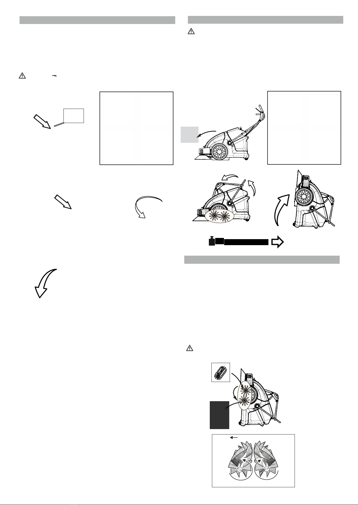
7.4 TIPPING THE SWEEPER
CAUTION! Risk of injury!
• Put ignition key into the “OFF” position and pull out.
•
Open front panel.
•
Disconnect batteries and remove.
•
Close front panel.
•
Put the drive bar into the highest position and fold in drive bar.
•
Tip the machine rearwards with the help of a second person
(first put steering roller in position - parallel to the direction of
running) and set up.
DANGER!
RISK OF CRUSHING when closing the
filter box.
7.5 CHANGING THE Roller Brushes
- The front brush is not subject to any wear and must not be
replaced, except where it is damaged.
- The roller brush does not have to be replaced if the
sweeping result is visibly worse due to wear of the brushes,
and readjustment of the roller brush is no longer possible.
- The roller brush consists of two segments connected by six
screws. Unscrew the screws using a suitable tool and remove the
segments individually.
- Insert the new segments into the roller brush and fasten
again with six screws.
- The direction of movement of the roller brushes Fig. 2
must be followed.
CAUTION! There is a risk of damage to the roller brush
if the brushes become jammed during fitting.
Fig.1
Forward direction of
running
Fig.2
Movement direction of the
roller brushes

30-40mm
16
7.6 S S R B C 7.7 CHANGING THE SIDE BRUSHES
The side brushes are subjected to wear. On abrasive surfaces,
wear to the brushes is faster than on smooth floors.
It is necessary to change the side brushes if these are
worn or damaged. Changing due to wear is necessary if the
sweeping result of the side brushes is visibly worsened and it
is no longer possible to readjust.
• Put ignition key into the “0” position and pull out.
• Raise the side brushes (transport position)
• Remove the side brushes (undo wing bolt).
• Change the side brushes.
• Put the side brushes on the take-up of the driver and fasten.
• Switch of the sweeper.
• Operate with the sweeper on level and smooth ground
that is recognisably covered with dust, sand or chalk.
• Open the front panel and set the roller brushes
adjustment to the centre position of the whole setting
area.
• Close front panel.
• Switch on the machine and allow the roller brushes to
rotate for approximately 15 seconds.
• Run the sweeper from the sweeping clearance.
• The impression of the roller brush (=sweeping
clearance) must be clearly visible on the ground. The
shape of the sweeping clearance forms a uniform
rectangle that is between 30 -40mm wide.
• Lowering the roller brush adjustment lever raises the
roller brush.
• As appropriate, repeat the pprocess until the desired
sweeping clearance is reached.
• Close front panel.
See also FITTING THE SIDE BRUSHES, chapter 4.4 Fig. 2-4
7.8 SETTING THE SIDE BRUSHES
It is necessary to adjust the side brushes if the wear of the
brushes visibly makes the sweeping result of the side brushes
worse.
• Set down the sweeper onto a level, dry and protected
surface.
• Raise the side brushes (transport position)
• Open front panel
• Undo the knurled nuts at the front left and/or right of the
side brush adjustment.
• Turn adjustment forwards to lower the side brushes further
• Fasten both knurled nuts again.
• Close front panel.
7.9 CHANGING THE FRONT SEALING RUBBER
The front sealing rubber must be replaced if there are tears
or it is worn, to guarantee a good sweeping result.
• Put ignition key into the “OFF” position and pull out.
• Raise the side brushes (transport position).
• Undo all four screws of the front sealing rubber and
remove.
• Remove the front seal completely.
• Replace the front sealing rubber.
Centre of
roller
brush
• Raise the side brushes.

17
7.10 SETTING / REPLACING SIDE SEALING RUBBER
The basic setting of the side sealing rubber is 1mm.
• Put ignition key into the “OFF” position and pull out.
• Tip the machine as required.
• To set the height, undo the fastenings (2 screws), readjust or
replace the side sealing rubber, align and fasten. 7.14 CONTACT DATA
Manufacturer: Stolzenberg GmbH &
Co. KG Hamburger Straße
15-17 49124
Georgsmarienhütte
T: +49 (0) 5401 / 8353-0
F: +49 (0) 5401 / 8353 - 11
E: service@stolzenberg.de
7.11 SETTING DRIVE BOWDEN CABLE /CANGING
Readjusting the Bowden cable is required if the driving force of
the machine is no longer sufficient.
• Put ignition key into the “0” position and pull out.
• Undo the lock nut.
• Setting/readjusting the Bowden cable
• Screw the lock nut tightly.
Dealer:
7.12
Readjusting the Bowden cable is required if the side brush no
longer folds in completely.
Folding out is done with springs
• Put ignition key into the “OFF” position and pull out.
• Undo the lock nut under the drive bar cover plate.
• Setting/readjusting the Bowden cable.
7.13 IMPORTANT SPARE PARTS AND CONSUMABLES
SETTING SIDE BRUSH BOWDEN CABLE /CANGING
Flat filter Item No. 100223
Roller Brush PA 0.4 V Item No. 114128
Item No. 110526
Side Brushes PA 0.6

18
7.15 MAINTENANCE WORK / MAINTENANCE TABLE
Instruction: The following maintenance work must be carried out by instructed and
authorised specialist staff at the set intervals.
RISK!
Risk of Injury The motor(s) need(s) to overrun for several seconds after being shut off.
In this time, you must keep clear of the drive area.
CAUTION! • Allow the equipment to cool down sufficiently before all maintenance and repair work
• Unplug the charger from the socket.
•
Disconnect the plus terminal from the battery.
You must read
T T S
, .
Activity Interval
Daily Weekly Every 50 hours
Chapter
Check machine for damage
and functional faults and remedy as appropriate. •
Check the battery charge; charge batteries as appropriate. • 4.8.3/
4.8.4
Empty the dirt-hopper • 5.8
Check roller brushes & roller brushes housing for damage, for foreign
clean or replace the roller brushes. •
7.5
Check side brushes for foreign bodies, straps etc.;
remove/clean as appropriate. •
Check side brush setting;
readjust or replace side brushes as appropriate • 7.7/
7.8
Check the condition of the dust filter; clean as appropriate • 5.7
Check the charge of the batteries before each usage •
4.8.3
Undertake all daily maintenance work
•
Check the sealing rubber in the roller brush area for
wear and damage; replace as appropriate
• 7.9/
7.10
Check dust filter for damage; replace as appropriate
• 5.7
Functional test of the entire machine
•
Check all toothed belts for tension, wear and
operation; replace as appropriate
•
Check the Bowden cables and all moving parts for
their smooth running; replace as appropriate
• 7.11/
7.12
Check the Bowden cables for extension of the pull cable
• 7.11/
7.12
Check safety components (end switch filter cover)
•
Conduct all daily and weekly maintenance work
•
Check battery condition; replace as appropriate
• 4.8.3
Check smooth running of the wheels (possibly replace any bearings)
•
Check all bearings for damage
•
Check all screws and fastenings
•
Check all covers and steel parts for firm seating
•
Check the operation of the charger
•
CAUTION! In the event that damage to the machine is
established, it must not be used until the damage has
been remedied by specialist staff.
bodies and for wear; remove any foreign bodies/

8
19
L
ONG
-TERM STOPPAGE OF THE SWEEPER
• INSTRUCTION
If it is stopped for a long period, the batteries must charge at
intervals of approximately 2 months so they are not damaged
by a deep discharge.
• Set down the sweeper onto a level, dry and protected
surface.
• Put ignition key into the “OFF” position and pull out.
• Secure sweeper against rolling away.
• Raise roller brush. To do this, adjust the lever to the
lowest position and stop.
• Raise the side brushes.
• Clean the dust filter.
• Empty the dirt-hopper.
• Clean the sweeper inside and out.
• Disconnect the battery.
S R
After the useful life of the machine is over, it must be
disposed of expertly. However, individual parts may
be thoroughly reused.
For the disposal of all equipment parts, the
disposal conditions specific for the location are
applicable.
INSTRUCTION Please ask your supplier about disposal
of the equipment.
WASTE DISPOSAL / ENVIRONMENTAL PROTECTION , chapter 4.2
See also
D
S, D,

9 C
20
M
M
M
M
M
M
M1 = Mainbrush
M2 = Shakerr
M3 = Fan
M4 = Sidebrush left
M5 = Sidebrush right
M6 = Drive
S1 = Main-/Keyswitch
S2 = Brushes ON/Off
S3 = Fan / Shaker
S4 = Sidebrushes On/Off
D1 = Working light
K1..K3 = Relay (max.70A)
F1 = Therm.Breaker Mainbrush 20A
F2 = Therm.Breaker Drive 25A
F3 = Filterbloc with switches and shaker 10A
F4 = Fan 15A
F5 = Sidebrushes 10A
Battery12V
M1 M2 M3 M4 M5 M6
K2 K3
S2 S3 S4
F1
F2
F3
F4
F5
D1
battery indicator
rt
br
grsw
ws
K1
S1
Charger
with charge-detection
cover-switch
chargecontact
1
1
2
2
3
3
4
4
5
5
6
6
7
7
A
A
B
B
C
C
D
D
E
E
Table of contents
Other STOLZENBERG Blower manuals

STOLZENBERG
STOLZENBERG KSV 910 User manual

STOLZENBERG
STOLZENBERG MATRIX MTX-900-V TRS User manual

STOLZENBERG
STOLZENBERG US 5 User manual

STOLZENBERG
STOLZENBERG NU5 User manual

STOLZENBERG
STOLZENBERG NU9 User manual

STOLZENBERG
STOLZENBERG CS 650 User manual

STOLZENBERG
STOLZENBERG KSE 910 User manual

STOLZENBERG
STOLZENBERG Tandem 900 KSE User manual


