N420529AEN
Reception
Preliminary warnings
Upon receipt of the package check that it is not damaged,
otherwise accept the goods with reserve, producing pho-
tographic evidence of any damage.
In the event of damage, notify the shipper within 3 days
of receipt of any damage by registered mail with return
receipt, submitting photographic evidence. Similar infor-
mation should be sent by fax to the manufacturer (juris-
diction will be at the Court Trento for any dispute).
No notice of damage will be accepted after 3 days from
delivery.
Package description
The packaging is made of suitable material and carried out
by experienced personnel.
There is a pallet underneath the packaging of the unit to fa-
cilitate transport and moving.
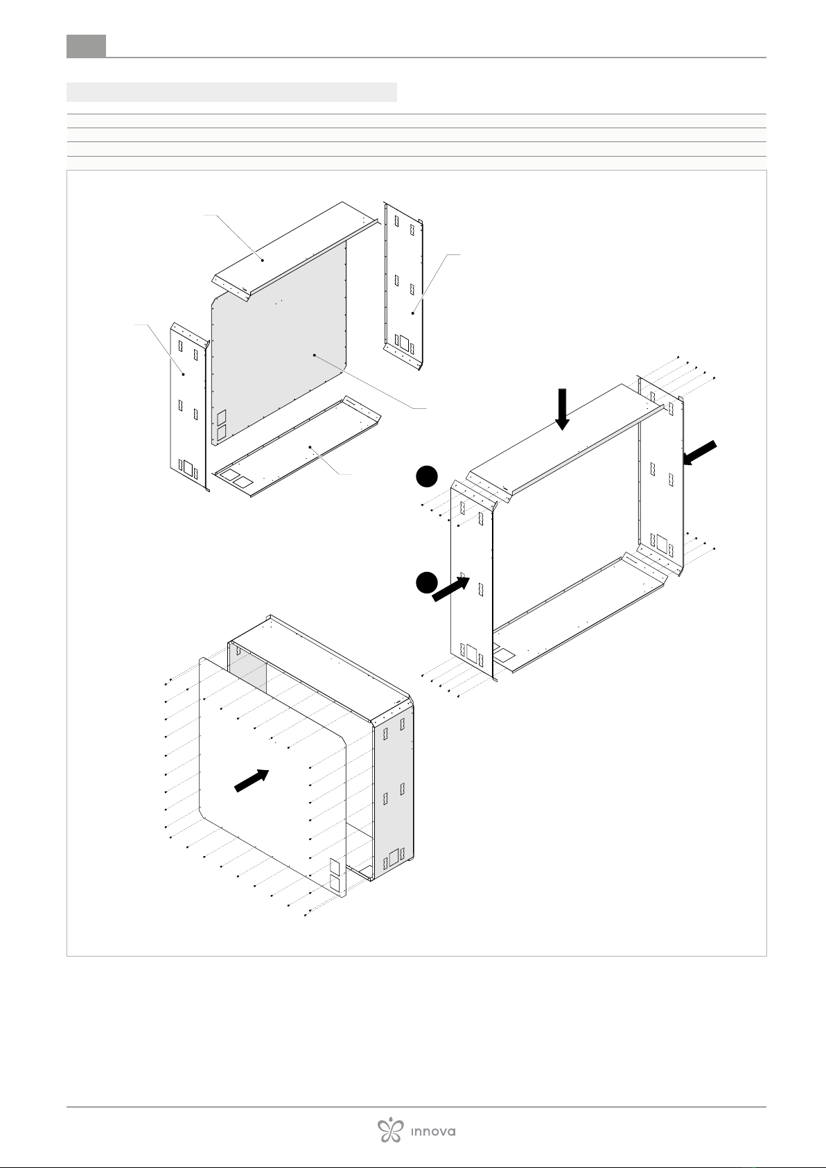
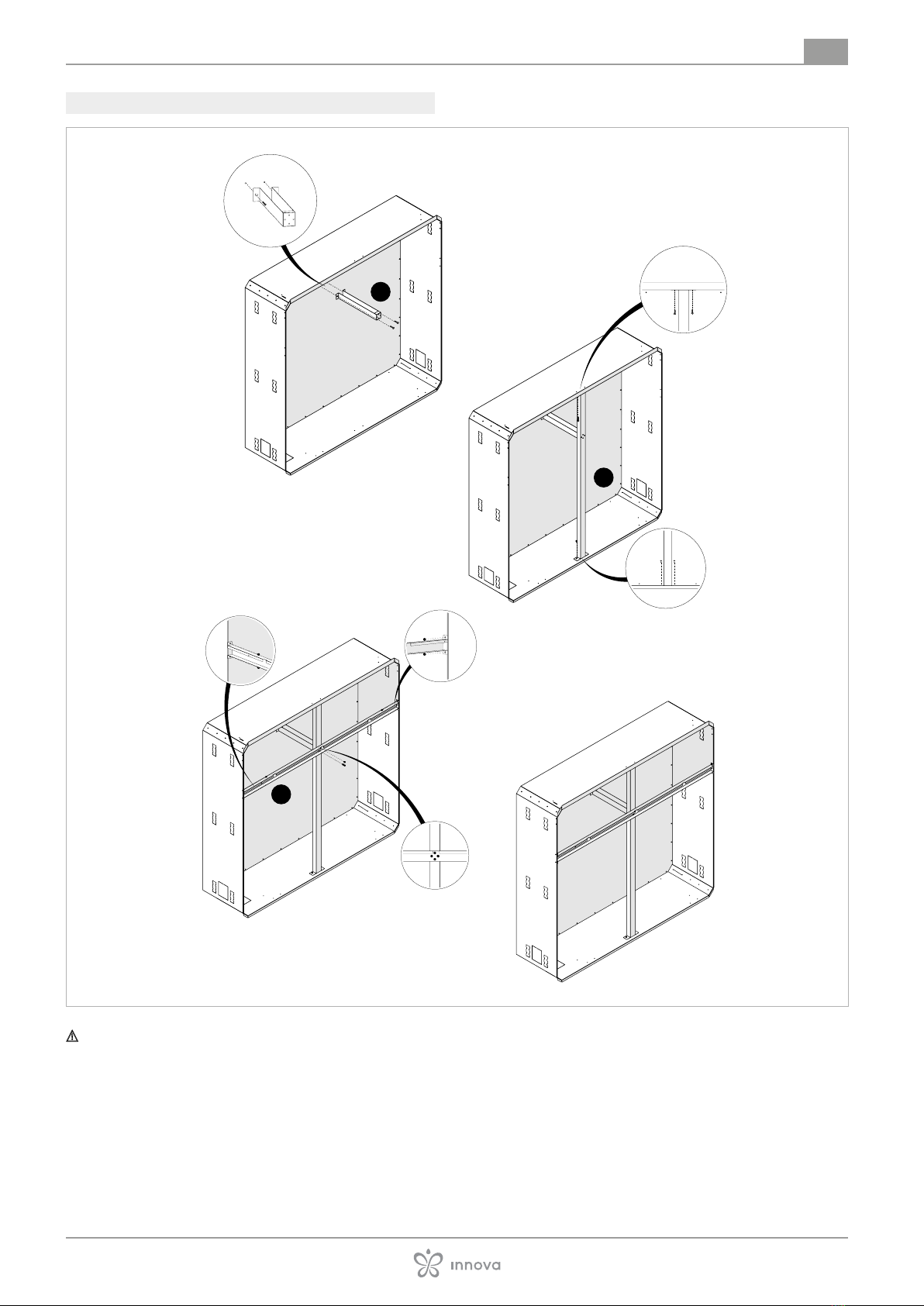
The formwork arrives disassembled, to be assembled dur-
ing installation.
Handling with packaging
Preliminary warnings
The appliance must be handled only by qualied person-
nel, adequately equipped and with equipment suitable
for the weight and dimensions of the appliance.
Before moving the unit, check the lifting capacity of the
machinery used following the instructions on the pack-
aging.
Stay clear of the area below and around it when the load
is lifted o the ground.
If a forklift truck is used, put the base in the appropriate
openings.
Avoid dangerous situations when using a hoist to lift the
appliance.
Movement methods
The product can be handled as follows:
• using a fork lift or a transpallet which can bear its weight
Use a small balance to prevent the pressure of the belts
damages the unit.
Unpacking
Preliminary warnings
Check that no components were damaged during trans-
port.
Dispose of the packaging components following the ap-
plicable waste disposal regulations.
The packing material (cardboard, staples, plastic bags, etc.)
must not be dispersed or abandoned in the surrounding
environment and must be kept out of children reach, as it
can be dangerous.
Remove the package
Remove the packing:
– transport the appliance to the installation area
– cut the strapping
– remove the packing
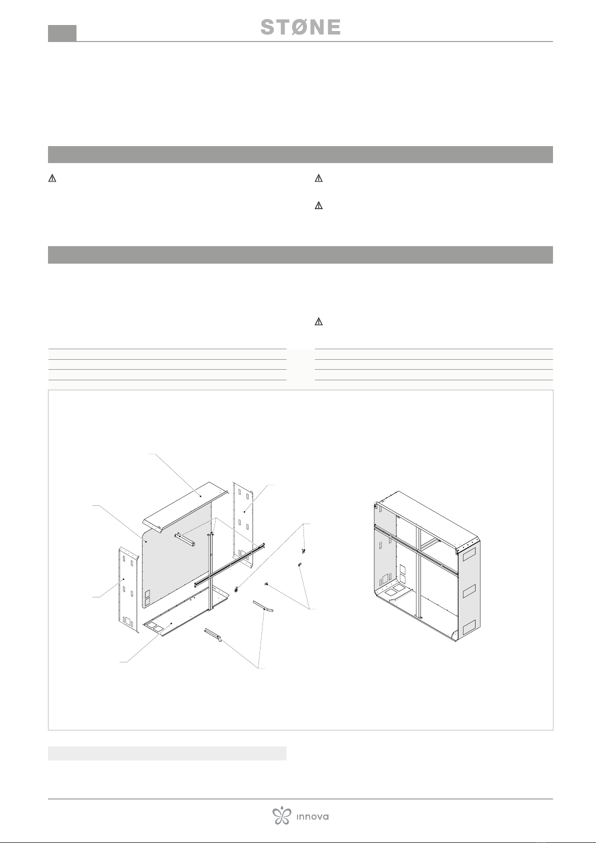
Accompanying material
The formwork arrives disassembled, to be assembled dur-
ing installation.
Check the presence of the individual components.
They are included with the appliance, inside the packaging:
• 1 instruction sheet
• screws
Installation site
The location of the appliance must be determined by the
plant engineer or a competent person and must take into ac-
count both purely technical requirements and any national/
local legislation in force.
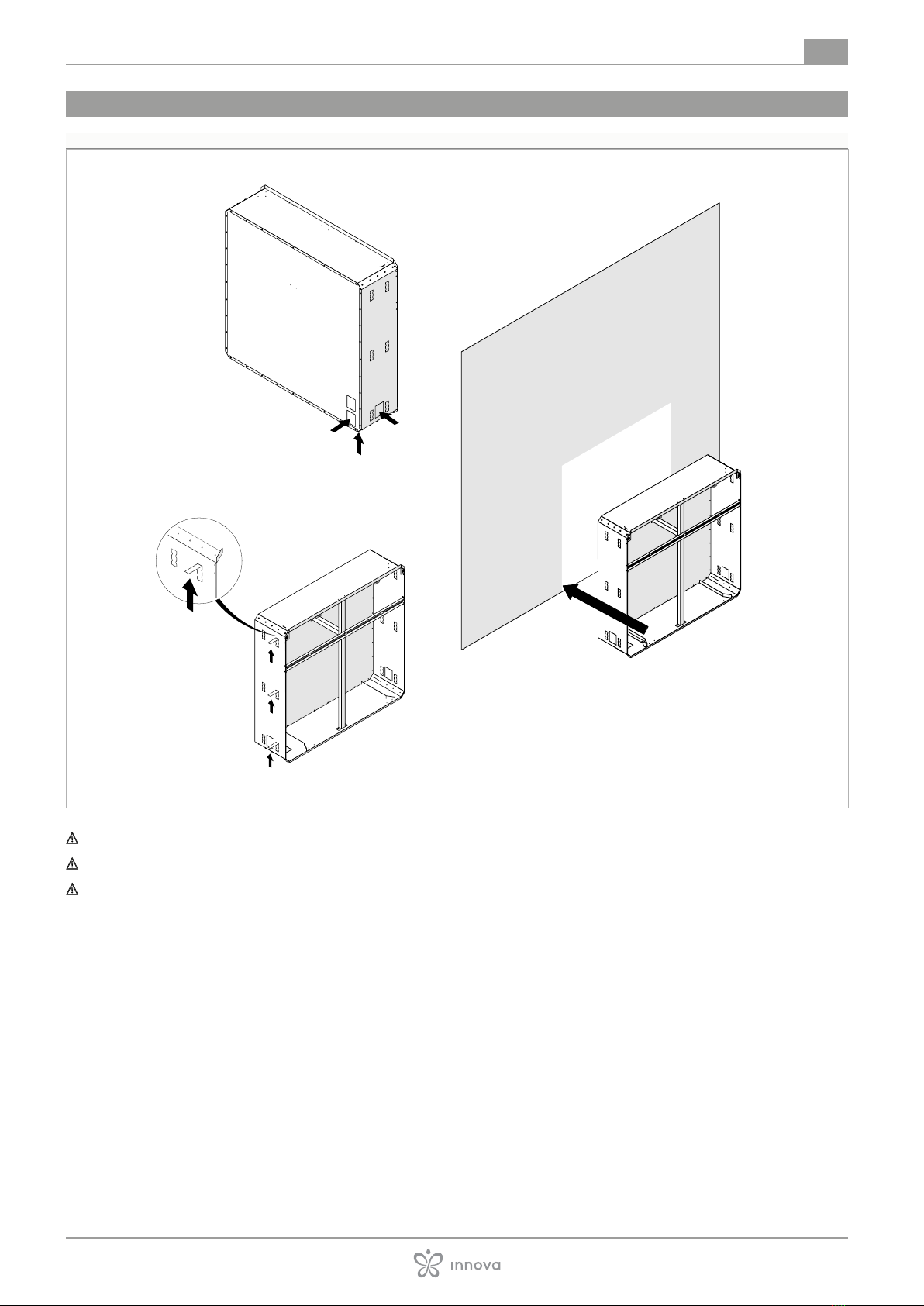
The appliance is intended for outdoor installation.
The planned installation methods are:
• built-in
Preliminary warnings
Avoid installing the unit near:
• environments with the presence of ammable or explo-
sive gases
• very humid environments (laundries, greenhouses, etc.)
• environments with aggressive atmospheres