StoneAge SA 36 User manual

1
Report 307-F-01b-2
Installation and Operation
Instructions
Stone Age Outdoor Fireplace
1.0 Introduction
The following provides instructions for the installation
and operation of the Stone Age Fireplace, manufac-
tured by Stone Age Manufacturing, Collinsville, Okla-
homa.
Three generations of fireplace knowledge and experi-
ence have gone into the design and construction of the
Standard series fireplaces. Standard Fireplaces are
certified to UL127 for the US, and ULCS610 for Can-
ada.
Assembly and Cutaway views of a SA36 fireplace are
shown in Figure 1.
Because of structural modifications required in an ex-
isting home, it is recommended that this fireplace be
installed by a professional installer, or by a builder in
new construction. Installation by a non-qualified per-
son may negate the warranty.
Keep these instructions for future reference.
2.0 Description
The fireplace is delivered as a kit with all components
necessary to complete the installation. Component
arrangements are shown in Figure 2. Components are
listed in Table 1. Specifications and installation di-
mensions are shown in Table 2.
A completed installation should include the following:
A. Fireplace items shown in Figure 2 and listed in
Table 1.
B. Top Mount Damper (Optional for Outdoor in-
stallations, sold separately) (Shown in Figure 28).
C. Chimney Cap (sold separately) (Shown in Figure
26).
D. Fireplace Grate (sold separately) (Shown in Fig-
ure 31).
E. Split firebrick (may be included or sold separate-
ly - confirm with your dealer)
F. Stone Age Multi-Purpose Ready-Mix Cement
(sold separately).
The Stone Age Fireplace has been tested and listed in
accordance with UL 127 and ULC S610 standards for
indoor or outdoor use, and is listed by OMNI-Test La-
boratories, Inc. for installation and operation in the
United States and Canada as described in this manual.
This fireplace is designed to supplement your current
heating system. It is not designed to be used as a pri-
mary heat source.
Ensure that appropriate building permits required by
local codes are obtained before installation in an exist-
ing home.
Ce manuel est disponible en français à www.stoneagemanufacturing.com.
This manual is available in French at www.stonea
g
emanufacturin
g
.co
m
.
SA36
Front View
Side
Cutaway
V
iew
Figure 1. SA36 Fireplace Assembly
& Cutawa
y
View

2
Table 1. Fireplace Components
Item Description 36”
1 Riser Legs 18 x 40
1A Riser Leg-Cross 18 x 39
2 Base Plate 33 x 46
3 Sidewall 11 x 33
4 Back Plate 22.5 x 40
5L/5R Slanted Sidewall 11 x 26
6 Back Header 11 x 46
7A/7S Lintel, Arch/Straight 11 x 46
8 Throat 23 x 23
at top
9A Flue (Note 2) 22 sq
10 Hearth 11 x 5 x 46
Note 1: Item numbers refer to component numbers in Figure
1.
Note 2: Flue sections are available but not provided in suffi-
cient quantity to reach a height of 16 feet. Flue sections
must be purchased separately.
Note: Drawings of the fireplace components,
with dimensions, are shown on page 15.
2.1 Specifications
Table 2: Clearances (See Figure 3)
Item Clearance Figure 3
Reference
Sidewall to Opening 18”
Top Trim to Opening 17” A
Side Trim to Opening 3”
Mantle to Opening 25” B
Floor to Opening 7”
Front Hearth Extension 24” C
Side Hearth Extension 12” D
Opening to Combustibles 48”
Minimum Ceiling Height 7’6”
Clearance around Chimney
flue
2”
Chimney Height from floor 16’
Note 1. This Fireplace is intended for use with solid wood fuel
or vented gas logs
Note 2: This fireplace has not been tested for use with glass
doors. To reduce the risk of fire or injury, do not install glass
doors.
Note 3: Do not use fireplace insert or other products not speci-
fied for use with this model. Use a fireplace grate when burning
wood.
Note 4: This fireplace has not been tested with an unvented gas
log. Do not install an unvented gas log set into this fireplace.
Note 5: Clay flue liners installed in flue section (item 9A, Figure
2) meet the specifications of ASTM Section C315-02.
Note 6: Make sure installation complies with local building
codes.
Note 7: Thermal Floor Protection of ½ “ of k=0.84 thermal
protection
Note 8: Floor under unit must be non-combustible to earth
Note 1: This Fireplace intended for use with solid wood
fuel or vented gas logs.
CAUTION: When using this appliance, the fireplace
damper (if present) must be set in the fully
open position.
Note 2: This fireplace has not been tested for use with glass
doors.
Note 3: Do not use fireplace insert or other products not
specified for use with this model. Use a fireplace grate
when burning wood.
Note 4: Clay flue liners installed in flue section meet the
specifications of ASTM Section C315-02.
Note 5: Ensure installation complies with local building
codes.
1
3
5R
2
3
3
3
1A
4
9A
5L
6
7
8
8
10
1
9A
9A
9A
Figure 2. Fireplace Components

3
2.2 Installation of Additional Equipment
WARNING: THIS FIREPLACE HAS NOT
BEEN TESTED FOR USE WITH
DOORS. TO REDUCE THE RISK
OF FIRE OR INJURY, DO NOT
INSTALL GLASS DOORS.
A. Do not install a fireplace insert unless it is tested
with this fireplace.
B. Cutting or drilling a hole into the floor or walls
for gas supply for a vented decorative gas appliance
(log), fresh air venting, or an ash dump, is accepta-
ble.
C. If a decorative gas appliance is installed, it must
be installed in accordance with the National Gas Fire
Code, ANSI Z223.1.
D. It must incorporate an automatic shutoff device.
E. Installation must comply with the Standard for
Decorative Gas Appliances in Vented Appliances,
ANSI Z21.60 (1991) or American Gas Association
draft requirements for Gas-Fired Log Lighters for
Burning Fireplaces, Draft No. 4 dated August 1993.
3.0 Installation of the Fireplace
WARNING: DO NOT USE SUBSTITUTE
MATERIALS IN THE
ASSEMBLY, INSTALLATION OR
OPERATION OF THIS
FIREPLACE. TO DO SO WILL
VOID THE WARRANTY AND
MAY RESULT IN FIRE AND
PERSONAL INJURY.
It is most important that the Stone Age fireplace be
installed according to the following instructions. It is
also important that local building codes be consulted
and followed. Improper installation could result in:
• Overheating, leading to fireplace failure
• Leakage of rainwater through and around the
chimney
• Cracks and settling because of poor founda-
tions
• Emission of smoke, sparks and gases into the
living area
• Combustion of materials adjacent to the fire-
place.
WARNING: THIS FIREPLACE HAS NOT
BEEN TESTED WITH AN
UNVENTED GAS LOG SET. TO
REDUCE THE RISK OF FIRE OR
INJURY, DO NOT INSTALL AN
UNVENTED GAS LOG SET INTO
THIS FIREPLACE.
Do not install this fireplace in a manufactured or mo-
bile home.
3.1 Preparations
Select a location in the home plans or outdoor living
area where all the minimum distances, as shown in
Table 2 and Figure 3 can be met. Proceed as follows.
Numbers in ( ) are item numbers from Table 1 and
Figure 2. Ensure the base on which the fireplace is to
be installed is a solid and level foundation and is com-
posed of non-combustible material, such as concrete.
Due to varying climates, soil conditions, building
codes, construction methods and materials in different
geographical regions, Stone Age recommends install-
ers review local building codes, consult with local
building officials and/or a structural engineer before
beginning the construction of any Stone Age product.
Figure 3. Clearances (Use with Table 2)

4
Pad or footings for outdoor installations should be a
monolithic pad constructed of steel reinforced con-
crete. Minimum footing specifications for fireplaces
built on stable soil, with overall height not exceeding
10 feet, are listed in Table 3. Locations with unstable
soil may require a deeper footing or the addition of
piers, to reach more stable subsoil or bedrock. Areas
with colder climates may also require deeper footings
or piers that reach below the frost line to prevent frost
heaving. Piers should include steel reinforcement that
extends into the footing above. See Figure 4.
For taller applications, consult with an engineer to de-
termine the structural requirements based on the over-
all height, and the weight of fireplace, chimney, and
finish materials. If custom hearths or additional ma-
sonry structure is to be attached to the fireplace kit, the
footing dimensions should be adjusted to include these
customizations.
If local building code exceeds the manufacturer’s
specifications for footings, follow the local code.
Table 3. Minimum Footing Specifications
Minimum Requirements for Footing 36”
Thinner Finishes-
Fabricated Stone, Stucco, Stain or Tile
A
B
C
6” - 8”
48”
52”
Thicker Finishes-
Full Veneer Natural Stone or Brick
A
B
C
12” - 18”
54”
58”
See Figure 5.
Footing requirements for indoor installations should
be determined based on local building code. Consult
with a structural engineer to determine the footing re-
quirements based on the overall height, and the weight
of fireplace, chimney, and finish materials. If custom
hearths or additional masonry structure is to be at-
tached to the fireplace kit, the footing dimensions
should be adjusted to include these customizations.
Use Stone Age’s Multi-Purpose Ready-Mix, or anoth-
er high temperature fire clay or refractory cement suit-
able for indoor or outdoor use, and mix according to
manufacturer’s instructions.
Once the fireplace is constructed you must wait at least
28 days before building a fire to give adequate time to
cure. This will provide ample time for any water resi-
due to evaporate, eliminating the adverse reaction of
the combination of water and fire.
Stone Age products are designed to be assembled us-
ing a 3/8” fully bedded mortar joint for the kit pieces.
Do not “butter the edges” of the kit pieces.
If the unit is to be installed indoors, do not use the Ris-
er Legs (items 1 and 1A, shown in Figure 2 and Table
1). Instead, install the fireplace on a solid base, such
as a cement pad or concrete blocks. Two courses of 8”
tall block will be slightly shorter than the riser legs of
the kit.
WARNING: DO NOT USE RISER LEGS FOR
AN INDOOR INSTALLATION. IN
THIS INSTALLATION, THE
VOID BELOW THE FIREBOX
COULD INADVERTANTLY BE
USED FOR THE STORAGE OF
COMBUSTIBLE MATERIALS,
WHICH COULD CREATE A FIRE
HAZARD.
Figure 4. Footing with Piers - Cutaway View
Figure 5. Footing with Piers
A
B
C
Front
Piers

5
3.2 Assembly of Components
Components that become broken during shipment and
handling can be mortared back together providing the
breaks or cracks are clean and the original alignment
can be maintained. Components broken into multiple
pieces must be replaced.
If this is your first Stone Age installation, it is suggest-
ed that you first assemble the components without
mortar to familiarize yourself with how the compo-
nents fit together. See Figure 2.
During the actual assembly with mortar, ensure each
layer of the kit is plumb, level, and square before pro-
ceeding to the next step of the assembly.
A. For Indoor installations, determine the height
above the floor you want to place the base plate (2).
The base plate, plus firebrick, will be approximately
4 1/2 inches thick. Mortar and set concrete blocks
into place to reach the desired height. Ensure the
block base is level and square. Set the base plate (2),
ensuring it is level and square. See Figures 6 & 7.
B. For Outdoor installations, align and set a Riser
Leg (1) and the Cross Leg (1A) on the footing, en-
suring they are plumb and level. See Figure 8.
C. Install the second Riser (1), ensuring it is plumb,
level and square. See Figure 9.
D. Set the base plate (2), ensuring it is level and
square. See Figure 10.
Note 6: From Step E to Step Q, the installation
procedure will be the same for indoor or outdoor
applications.
Figure 8. Riser Leg & Cross Leg
1
2
1
Figure 9. Riser Legs & Cross-Leg
Figure 10. Base Plate
1A
2
Base Plate
Concrete Block
Base
Figure 6. Block Base
For Indoor Use
Figure 7. Kit Base Plate

6
E. Install the lower sidewalls (3), ensuring they are
level and square. See Figure 11.
F. Install the middle sidewalls (3), ensuring they are
level and square. See Figure 12.
G. Install the back plate (4). See Figure 13.
H. Install upper sidewalls (5L) and (5R), ensuring the
correct piece is placed in position. The correct posi-
tion is when the inner wall, outer wall and front are
parallel with the middle wall pieces. Place each so
the front is set back 3½ inches from the front of the
middle wall piece below. See Figures 14 & 15.
H. Install Back Header (6). See Figure 16.
3
3
5L
Figure 11. Lower Sidewalls
Figure 15. Upper Sidewalls
Figure 12. Middle Sidewalls
Figure 13. Back Plate
5R
3
3
4
5L 5R
6
Figure 14. Upper Sidewalls –Top View
Fi
g
ure 16. Back Header

7
I. Line the firebox, using split firebrick and 1/4-inch
mortar joints. Install firebrick on the floor first, with
1/4-inch of Stone Age Multi-Purpose Ready-Mix or
other high temperature mortar. See Figure 17.
J. Install firebrick on the back wall, with the brick
laid on edge. See Figure 18.
K. Install firebrick on the side walls, with the brick
laid on edge. The brick lay up on approximately 1/3
of the upper sidewall, and a notch should be cut in
the front brick on each side, to allow them to clear
the front lintel piece (to be installed later). See Fig-
ure 19.
L. Install the front lintel piece, (7A, for arched lintel,
as shown) or (7S, for straight lintel kits). See Figure
20.
7 A
Figure 19. Sidewall Firebrick
Figure 18. Back Wall Firebrick
Figure 20. Front Lintel
Fi
g
ure 17. Floor Firebrick

8
M. Install the tapered front and rear throat pieces.
See Figure 21.
N. Install the first Stone Age masonry chimney sec-
tion (9A), with the tile extending upward. Fill the
void on the bottom with mortar to create a smooth
transition. See Figure 22.
O. Install the remaining chimney sections (9A), fully
bedding each piece in mortar, and filling in the gap
between the clay tiles in each section. Parge the
joints to create a smooth transition between each
chimney section. Note that if a tile is chipped or
slightly out of square, it may be used as long as it the
joints are filled and smoothed with high temperature
mortar. See Figure 23. If additional chimney is
required to penetrate a roof or structure, refer to
Section 4.0 for more detailed instructions.
P. Install the hearth piece (10) if using this compo-
nent, and any hearth extension. See Figure 24.
8
8
9A
9A
9A
Figure 24. Hearth
Figure 23. Chimney Complete
Figure 21. Throat Pieces
Figure 22. Chimney Flue
9A
10
9
Q. Ensure the Table 2 and Figure 3 clearances and
distances are maintained. Ensure that the hearth and
flooring under and in front of the hearth are made of
fully non-combustible materials, not just a non-
combustible floor covering. When the hearth instal-
lation is complete, if the chimney complete and is not
continuing through a roof or structure, you are ready
to install the exterior finish. If the chimney will be
continuing through a roof or structure proceed to
Paragraphs 4.0 and 4.1 before beginning the finish
application.
If installing a mantel and side trim, particularly if it
is wood or other combustible materials, ensure the
minimum distances shown in Table 2 and Figure 3
are met.
3.3 Exterior finishing
The exterior of the fireplace may be finished in any
masonry-compatible material. Mantle and exterior
veneers may be fabricated stone, thin veneer or full
bed depth natural stone, tile, brick or stucco.
If the exterior finish will be stucco, stain, tile or manu-
factured thin stone, wrap the outside of the firebox
with metal lathe. Attach metal lathe to the firebox us-
ing concrete nails, tapcons, masonry or concrete an-
chors. Natural stone veneers (whether full bed depth
or thin veneer), full size brick, concrete pavers, CMU
block, etc., do not require metal lathe.
Ensure the same refractory mortar used to build the kit
is used to install these materials.
4.0 Installation of Chimney Through a
Roof or Structure
A. The chimney is completed by stacking as many
flue sections as necessary to reach the desired chim-
ney height. Chimney plumbing can either be straight
through the ceiling and through the roof, or if the fire-
place is installed on an outside wall, the chimney can
be external to the house. When needed, offset blocks
can be used for the chimney and should be engineered
to structurally support the offset with CMU or custom
fabricated steel posts and/or angle iron capable of
supporting the weight and height of the chimney.
Never exceed more than a 30 degree angle when off-
setting a chimney.
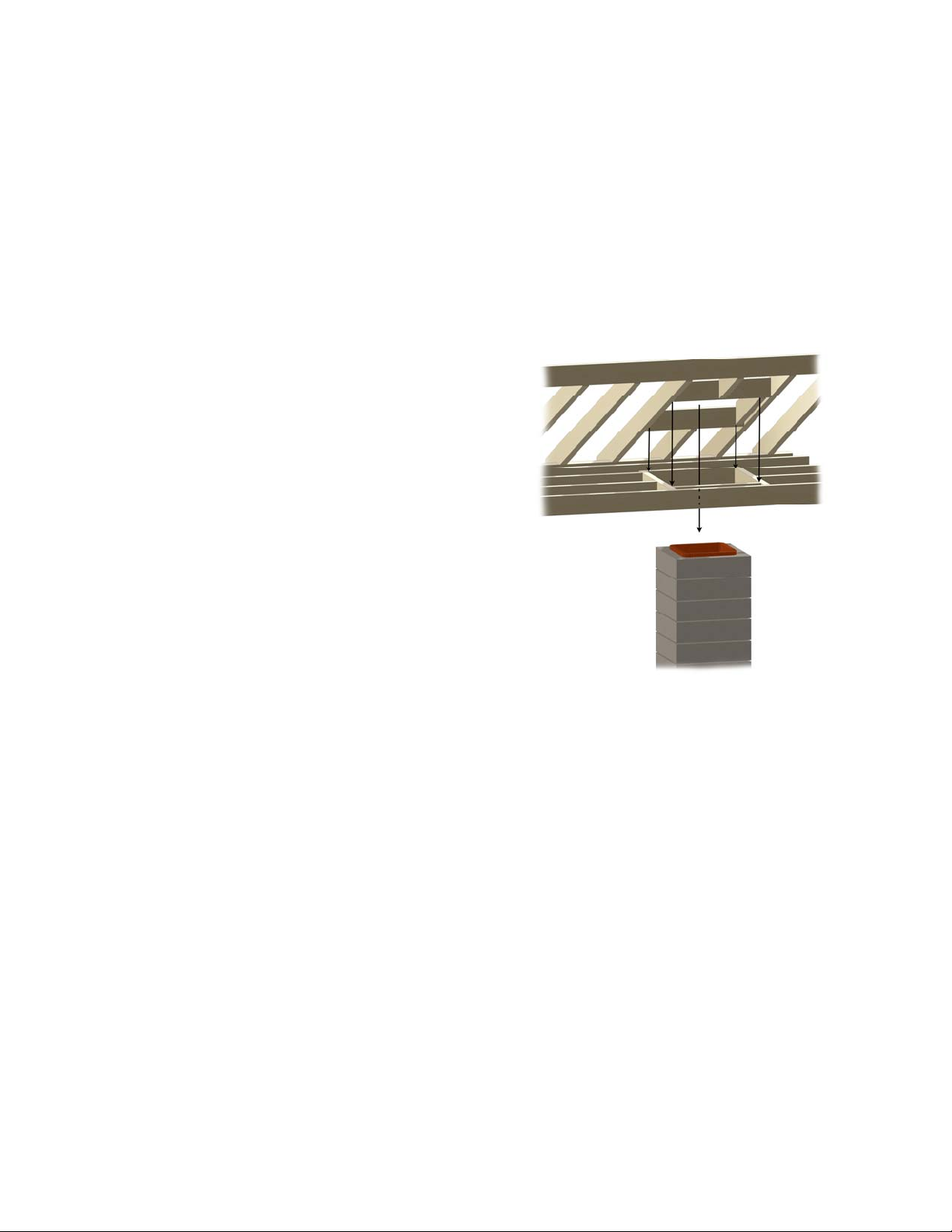
B. If chimney exit opening does not already exist
locate the point where the chimney will exit the roof
by plumbing down to the center of the fireplace
chimney. Drive a nail into the roof to mark the cen-
ter.
C. Measure to all sides of the nail and mark the re-
quired opening, and then cut a hole in the roof. Re-
member that the hole is measured on the horizontal,
and then projected to the roof. The hole may then be
larger, depending on the pitch of the roof. See Fig-
ure 25.
D. Frame the opening in the roof, maintaining the
required minimum 2” clearances to combustibles
around the chimney. See Table 2. When the chim-
ney passes through a ceiling to an upper floor, make
sure the 2-inch clearance is maintained with framing
where it passes through the ceiling. Exterior veneer
attached directly to the chimney measuring 2” or
more is acceptable for needed clearance.
WARNING: DO NOT PACK REQUIRED AIR
SPACES WITH INSULATION OR
OTHER MATERIALS.
E. Continue to add flue sections, extending the
chimney through the roof.
F. As the chimney extends through the attic to the
Figure 25. Roof Penetration

10
roof, attach securing straps to rafters and joists to
provide stability if required by local building code.
G. Install roof flashing appropriate to the roof pitch.
H. At the top of the chimney, use mortar to create a
cap, sloping away from the clay flue and running out
to the edge of the finish material, to assist with water
drainage. Install the chimney cap following instruc-
tions provided. This will protect the chimney from
rain, birds, animals and leaves. See Figure 26.
4.1 Height of Chimney
Figure 27 illustrates the proper height of the chimney
top. Correct height depends on the chimney’s location
on the roof and distance from the peak of the roof.
Surrounding trees, other buildings and hills may also
be a consideration.
If the chimney top is not high enough, unusual
downdrafts may occur, resulting in undesired smoke
spillage. For a more thorough explanation of the fig-
ure 27 illustration, this is the traditional 2/10 rule. The
center of your chimney should be a minimum of two
feet higher than any roof or projection within ten feet
horizontally from the chimney center. This means the
chimney does not have to extend above the peak of the
roof if the peak is more than 10’ away horizontally.
Once the chimney is ten feet away and extended two
feet above roof structure at that distance, the height is
sufficient, but it should never be less than three feet
taller than the point where it penetrates the surface of
the roof.
4.2 Installing a Damper
A. If installing a damper with this model Stone Age
fireplace, use a top-mount damper, and follow the
instructions included with the damper. Properly ori-
ent the taller side of the damper with the prevailing
winds in your area. See Figure 28.
B. Connect the pull cable at the cable guide of the
damper and drop through the chimney.
C. Install bracket towards the front of the firebox
wall, about 20 inches above the firebox floor. The
bracket will capture the damper operating cable.
Use a ¼” masonry bit to avoid cracks in the
firebrick. See Figure 29.
Figure 26. Mortar Cap and Chimney Cap
Figure 27. Chimney Height
Prevailing Wind
Cable
Adhesive
Figure 28. Install Top-Mount Damper
2’ Higher
Chimney Must be at Least 2’ Taller
Than Anything Within a 10’ Radius
10’ Radius
Chimney Must be at Least 3’
Above The Roof Penetration Point
3’ Above

11
D. Insert the pull cable through the bracket and
adjust the length per damper manufacturer’s instruc-
tions. Attach handle assembly to the bracket and
check damper for proper operation. See Figure 30.
5.0 Operating Instructions
5.1 Safety Precautions
A fireplace can bring many hours of enjoyment, com-
fort and warmth if operated and maintained properly.
Certain safety precautions must be observed to elimi-
nate the dangers associated with fire and provide a
satisfactory, smoke free fire.
A. When burning wood use solid, seasoned wood
only. Do not use scrap wood or artificial wax based
logs, treated coal or woods dipped in pine tar or
pitch.
B. Never use gasoline or other combustible liquids
when starting a fire.
C. Keep the chimney damper open while burning a
fire. Do not interrupt air flow. Ensure sufficient air
is present to support combustion. The manufactur-
er of this fireplace is not responsible for interior
smoke resulting from lack of combustion air.
CAUTION: WHEN USING THE DECORATIVE GAS
APPLIANCE (VENTED GAS LOGS); THE
FIREPLACE DAMPER MUST BE SET IN
THE FULLY OPEN POSITION.
D. Keep a screen in front of the fireplace except
when tending the fire.
E. Keep combustible furniture/pillows at least four
feet from the opening.
F. Never leave the fire unattended.
G. Be extremely careful when adding wood and
handling fireplace tools. Never throw, kick or by
any other means force wood into the firebox as this
could damage the firebrick and fireplace walls that
could result in permanent damage and void the war-
ranty. Stress cracks from thermal cycling are nor-
mal.
H. Do not alter this fireplace to the extent that it
would jeopardize the structural integrity of the fire-
place. Drilling or cutting a hole for a gas line, fresh
air vent or ash dump is acceptable. Use only Stone
Age authorized equipment with this fireplace.
5.2 Selection of Wood
Use cured wood logs only. Scrap wood produces
sparks. Treated wood, coal, or woods dipped in pine
tar should not be used because they may leave a com-
bustible residue in the fireplace and chimney.
Use of seasoned wood is preferred.
The amount of heat available from logs will depend on
the type of wood, its dryness, quantity of wood and the
size of the logs. Ten pounds of twigs will produce as
much heat as a 10 pound log, but will produce it much
faster because the air supply is more available.
Bracket &
Anchors
Figure 29. Install Bracket & Anchors
Figure 30. Bracket and Handle Assembly
Handle
Assembly

12
5.3 Softwood vs. Hardwood
Wood is divided into two classes, hard and soft woods.
Each has a use in a fireplace and each has advantages
and disadvantages.
The hardwood category includes such woods as oak,
walnut, birch, elm and maple. Softwoods include
pine, fir, cedar and spruce.
Selection of wood depends on the type of fire you
want. Softwoods are good to offset a morning chill
because the fire develops faster. Hardwoods are pref-
erable for a slower burning and uniform heat output.
Softwoods contain a highly flammable resin that will
leave creosote soot in the chimney flue. This often
results in sparking. Burning softwood exclusively will
require more frequent inspection and cleaning of the
chimney.
Experienced fire builders often use small amounts of
softwood kindling and newspaper when starting a split
hardwood log fire.
5.4 Seasoned Wood
Most freshly cut “green” wood will not burn well and
will smoke. The pressure of moisture and resin inside
green wood will build under heat and explode as
sparks. Therefore, it is recommended that only sea-
soned wood be used in your fireplace.
Most wood requires 9 to 12 months of seasoning and
drying to reduce the moisture content enough to pro-
duce good steady fires. Ensure that you buy only sea-
soned wood, or if you buy green wood (usually
cheaper), store it properly to aid in the seasoning pro-
cess. The following steps will assist in the seasoning
process.
A. Stack wood loosely to permit maximum air cir-
culation.
B. Do not stack wood on the ground. Use a wood
rack or stack on scrap lumber. Storage on the ground
will cause rotting and insect infiltration.
C. Cover wood stacks with a tarp so that it is not
excessively exposed to the elements such as snow
and rain.
D. Do not stack wood against the walls of your
home.
5.5 Building a Fire
A. Use a log grate (sold separately) with your fire-
place. This will contribute to good air circulation
around the wood, and keep the wood out of the ash.
This grate is shown in Figure 31.
B. Close windows located near the fireplace when
first lighting a fire to reduce the possibility of smok-
ing. It can be reopened once a draft has been created
through the chimney.
WARNING: NEVER USE GASOLINE,
GASOLINE-TYPE LANTERN
FUEL, KEROSENE, CHARCOAL
LIGHTER FLUID OR SIMILAR
LIQUIDS TO START OR
“FRESHEN UP” A FIRE IN THE
FIREPLACE. KEEP ALL SUCH
LIQUIDS WELL AWAY FROM
THE FIREPLACE WHILE IT IS
IN USE.
C. Do not overload the wood grate with wood. Three
to four logs on the fire at one time are sufficient.
Too much wood on the fire at one time can result in
“over firing,” and too much heat in the firebox, caus-
ing damage to the fireplace.
D. When lighting a fire in a cold chimney, a
downdraft may be created, letting a little smoke into
the room. To correct this, hold a wadded newspaper
in the firebox and light it. This will create an updraft
and clear the flue of cold air.
E. Remove any excess ash from the fireplace. Ex-
cessive ash may reduce airflow. Some owners prefer
to leave a small layer to insulate the cold refractory
brick below the grate, helping fire starting.
F. Open and close the damper to ensure it operates
properly. Leave it in the full open position when
starting a fire and while the fire is burning.
G. Center the grate over the bottom hearth of the
firebox.
Figure 31. Log Grate

13
H. Crumble several newspapers across the fire area
below the grate. Criss-cross kindling wood on top of
the grate, above the newspaper.
I. Lay three logs on the grate; two side by side and
the third in pyramid fashion on top. Split logs will
start faster. Ensure there is space between the logs
for air circulation. As the air is heated, it is drawn
upwards through the space between the logs, creating
more combustion.
J. Light the paper at both sides of the firebox.
Caution: The fireplace requires air for operation.
Ensure there is sufficient air so that other
fuel burning appliances are not starved of
combustion, ventilation, and dilution air.
K. Set the screen in front of the firebox to prevent
the escape of sparks and embers.
L. Ensure the fire remains centered in the firebox.
Don’t let it move to the front part. Move it back with
the poker.
M. Add wood to the fire as necessary.
CAUTION: Be extremely careful when adding wood
to the fire. Use proper fireplace tools and
wear gloves. Un-split logs will be less stable
and may be more likely to roll out of the
fireplace if not placed carefully on the log
grate.
6.0 Cleaning, Inspection and
Maintenance
As is the case with most other equipment, cleanliness
is the best maintenance practice and will contribute too
many hours of warmth and pleasure.
WARNING: DO NOT CLEAN THE FIRE-
PLACE WHEN IT IS HOT.
A. Creosote – Formation and Removal. When wood
is burned slowly, it produces tar and other organic
vapors, which combine with expelled moisture to
form creosote. The creosote vapors condense in the
relatively cool chimney flue of a slow burning fire.
As a result, creosote residue accumulates on the flue
lining. When ignited, this creosote makes an ex-
tremely hot fire. The chimney shall be inspected at
least twice a year during the heating season to deter-
mine when a creosote buildup has occurred. If a sig-
nificant layer of creosote has accumulated (3 mm or
more), it should be removed to reduce the risk of a
chimney fire.
B. Disposal of ashes - Ashes should be placed in a
metal container with a tight-fitting lid, and taken out-
side and placed on the ground, well away from all
combustible materials, pending final disposal. If the
ashes are disposed of by burial in soil or otherwise
locally dispersed, they should be retained in the
closed container until all cinders have thoroughly
cooled.
C. The grate may be removed from the firebox for
cleaning. However, ensure it is returned prior to lay-
ing the next fire.
D. Keep the fireplace screen clean so air flows
freely through it.
E. Spot check the refractory bricks and mortar for
small cracks. It will expand slightly with the heat,
and then contract as it cools. Replace refractory
bricks when the cracks open more than ¼”; or when
pits become extensive and deeper than 3/16”; or
when any piece of refractory larger than 2 inches in
diameter becomes dislodged.
F. If creosote has accumulated, it should be re-
moved to reduce the risk of a chimney fire. Clean
the chimney as outlined below or have the chimney
cleaned by a professional chimney sweep.
WARNING: DO NOT USE CHEMICAL
CHIMNEY CLEANERS THAT
ARE POURED ON A HOT FIRE.
THE CHEMICAL CLEANER CAN
BE DANGEROUS AND
GENERALLY WILL ONLY
WORK ON THE FLUE SECTION
NEAREST THE FIRE, LEAVING
THE REST OF THE FLUE
UNAFFECTED.
G. Inspect the top cap and opening in your chimney
top and remove any debris that could clog it. If pos-
sible, birds will often nest there, and it must be kept
clear of nest material.

14
H. Check the metal flashing and seals around the
chimney. Seal any cracks or loose nail heads to pre-
vent roof leaks.
I. Cover the firebox opening with a damp sheet and
seal with masking tape to retain soot in the firebox
while cleaning.
J. Inspect the entire flue from the top down for ob-
structions. Use a flexible handled cleaning brush. If
the chimney contains offset/return elbows, clean
from the top down to the offset, then from the fire-
box up to the offset.
K. Check the flue from inside the fireplace with the
damper open for obstructions.
L. After completion of cleaning, use a vacuum
cleaner to remove all soot and residue from the fire-
box.
7.0 Finishing Specifications
Approximate finishing specifications, firebrick count,
and mortar coverage are estimated in Table 4 below.
Coverage amounts may vary due to weather condi-
tions, type of finish material, size of mortar joints, and
skill and efficiency of the mason or installer.
Table 4 does not account for waste. Add the appro-
priate waste factor for your material type and skill lev-
el.
Table 4. Finishing Requirements
Kit Components
Surface Area
Corner Length
100 square feet
32 Linear feet
Ready-Mix Mortar Required
for Kit Assembly 4 Buckets/Bags
Mortar Required for Kit
Finishing 4 - 7 Buckets/Bags
Firebrick Required 85 Split Brick
Additional Chimney
(Per Chimney Section)
Surface Area:
Corner Length:
4 square feet
2 Linear feet
Ready-Mix Mortar Required
for Assembly 1/8 Bucket/Bag
Mortar Required for
Finishing
1/8 - 1/4
Buckets/Bags
THIS SPACE INTENTIONALLY LEFT
BLANK

15
2
Base Plate
4
Back Plate
8
Throat
1
Riser Leg
1A
Cross Leg
6
Rear Header
3
Lower/Middle
Side Wall
10 Hearth
9A
Flue
7S
Straight Lintel
7A Arched Lintel
5L &R
Upper Side Wall
Fireplace Components
SA36/SA36-STR
23”
23”
46”
5”
46”
23
”
40”
22.5”
11
”
46”
7
”
11”
33
”
22”
26”
46”
33”
40”
18”
18”
39”
46”
11
”
46”
11
”

16

17
Stone Age Fireplace Instructions
Models SA36/SA36-STR
Revised 10/2018
Printed in USA © 2013-2018, All Rights Reserved
Stone Age Manufacturing, Inc
LIMITED WARRANTY
The products of Stone Age Manufacturing, Inc. (“Stone Age”) have
been carefully manufactured and the components assembled to give the
customer a quality product. Stone Age warrants to the original pur-
chaser the materials that it provides to the customer against defects in
manufacture for a period of twenty-five (25) years from the date of pur-
chase on UL-127 listed fireplaces, for a period of five (5) years from the
date of purchase on all unlisted fireplaces, fire pits, and other masonry
components. Other accessory items or components offered, but not
produced by Stone Age Manufacturing, Inc., shall be covered by their
manufacturer’s warranties. This Limited Warranty covers only actual
manufacturing defects in the Stone Age product and does not cover de-
fects or faulty workmanship in the installation of the product or the ma-
sonry or other structure in which it is installed. Also this warranty does
not cover items that have been damaged due to over-heating, modifica-
tion, improper storage or maintenance. Stone Age shall repair or re-
place, at its option, any defective Stone Age product component upon
receipt of written notice addressed to Stone Age. This Limited Warran-
ty covers only replacement of any defective components within the
product itself occurring during the warranty period and does not cover
the cost of installation or removal from a fixed location. NO OTHER
WARRANTIES, EXPRESS OR IMPLIED, ARE MADE, INCLUDING
IMPLIED WARRANTIES OF MERCHANTABILITY AND FITNESS
FOR PARTICULAR PURPOSES WHICH ARE SPECIFICALLY
DISCLAIMED. Stone Age is not liable for damages or injury to per-
sons or property or other incidental or consequential damages.
Stone Age Manufacturing, Inc.
11107 E. 126th St. N., Collinsville, OK 74021
WWW.Stoneagefireplaces.com
Table of contents
Other StoneAge Outdoor Fireplace manuals


Popular Outdoor Fireplace manuals by other brands


The Fireplace
The Fireplace JETMASTER 700 D installation instructions

Superior
Superior VRE4543EN Installation and operation instructions

Napoleon
Napoleon PATIOFLAME GPFN Installation and operation instructions

Endless Summer
Endless Summer Dakota GAD19101ES owner's manual

Vermont Castings
Vermont Castings ODGSR36A Homeowner's installation and operating manual

FEUERHAND
FEUERHAND PYRON user manual