Storch 69 09 30 User manual

Montageanleitung
zum Oberbehälter für alle STORCH-Airlessgeräte der LP-Serie
mit flexiblen Ansaugsystemen
Montage-instructies
voor het bovenreservoir voor alle STORCH-airlessapparaten van
de LP-serie met flexibel aanzuigsysteem
Instructions de montage
pour le réservoir supérieur de tous les appareils airless STORCH
de la série LP avec système d‘aspiration flexible
Istruzioni per il montaggio
per il serbatoio superiore per tutti gli apparecchi Airless STORCH
della serie LP con sistema di aspirazione flessibile
Assembly instructions
for the upper container for all STORCH Airless devices from the
LP series with a flexible intake system
Montážní návod
k horní nádrži pro všechny STORCH Airless přístroje série LP s
flexibilním systémem sání
DE
NL
FR
IT
GB
CZ

2
Ansaug-
rohr
Spann-
laschen
(hier drehen,
falls der Schlauch
knickt)
flex. Ansaugschlauch
(nicht knicken!)
DE
STORCH Service Abteilung
Telefon: +49 (0)2 02 . 49 20 - 112
Fax: +49 (0)2 02 . 49 20 - 244
kostenlose Service-Hotline: 08 00. 7 86 72 47
kostenlose Bestell-Hotline: 08 00. 7 86 72 44
kostenloses Bestell-Fax: 08 00. 7 86 72 43
(nur innerhalb Deutschlands)
Entfernen Sie zunächst den Ansaugfilter vom Rohr des flexiblen Ansaugsystems und trennen Sie den Bypassschlauch
sowie die Schlauchklammer vom Ansaugrohr.
Verlegen Sie dann das Rohr mit dem Ansaugschlauch so, wie auf den Fotos dargestellt. Achten Sie darauf, daß der
Schlauch nicht geknickt oder verdreht ist. (Gegebenenfalls läßt sich das Saugrohr in der Schlauchverpressung mit gerin-
gem Kraftaufwand drehen.)
Befestigen Sie nun das Saugrohr mittels der Spannlasche am Rahmenrohr wie dargestellt.
Montage an Gerät mit Tragegestell:
Das nach oben zeigende Saugrohr umwickeln Sie im Gewindebereich mit 3 - 4 Lagen des beigefügten Teflonbandes
und schrauben den Oberbehälter dort auf.
Schrauben Sie den originalen Bypassschlauch inkl. Adapter aus dem Bypassventil heraus und verwenden Sie dafür den
beiliegenden blauen Schlauch.
Umwickeln Sie dafür den Gewindebereich des blauen Schlauches mit 2 - 3 Lagen des beigefügten Teflonbandes und
schrauben Sie diesen in den Anschluß vom Bypassventil.
Das Ende des Bypassschlauches führen Sie dann von außen durch das Loch im Behälterdeckel (ca. 10 cm weit). Sichern
Sie den Schlauch gegen Herausrutschen durch Anbringung des beiliegenden Kabelbinders wie auf dem Foto dargestellt.
Ober-
behälter
Ansaug-
rohr
Spann-
laschen
(hier drehen,
falls der Schlauch flex. Ansaugschlauch
knickt) (nicht knicken!)
Montage an Gerät mit Fahrgestell:

3
Setzen Sie den Deckel auf den Oberbehälter. Das Gerät ist nun einsatzbereit.
Bypassventil
blauer Bypassschlauch
Deckel
Kabelbinder
Behälter-
deckel
Bypass-
schlauch

4
aanzuigbuis
klem-
verbindingen
(hier draaien
indien de slang soepele aanzuigslang
een knik vertoont) (niet knikken!)
boven-
reservoir
aanzuig-
buis
klem-
verbindingen
(hier draaien
indien de slang soepele aanzuigslang
een knik vertoont) (niet knikken!)
NL
STORCH serviceafdeling
Tel.: +49 (0)2 02 . 49 20 - 112
Fax: +49 (0)2 02 . 49 20 - 244
Gratis service-hotline: 08 00. 7 86 72 47
Gratis bestel-hotline: 08 00. 7 86 72 44
Gratis bestel-fax: 08 00. 7 86 72 43
(alleen binnen Duitsland)
Verwijder eerst de aanzuigfilter van de buis van het soepel aanzuigsysteem. Maak de omleidingslang alsook de
slangklem los van de aanzuigbuis.
Plaats de buis met de aanzuigslang zoals op de foto’s. Zorg ervoor dat de slang geen knik of kromming vertoont.
(Eventueel kan u de zuigbuis met geringe krachtinspanning in de voorgevormde slangkrimp draaien.)
Bevestig de zuigbuis nu met behulp van de klemverbinding op de framebuis. Zie foto’s.
Rond de naar boven wijzende zuigbuis wikkelt u, waar de schroefdraad zich bevindt, met 3 à 4 lagen van het
bijgeleverde teflonlint. Schroef het bovenreservoir daarop.
Schroef de originele bypass-slang incl. adapter uit het bypass-ventiel en gebruik hiervoor de meegeleverde blauwe
slang. Onwikkel het schroefdraadgedeelte van de blauwe slang met 2-3 lagen van de meegeleverde teflonband en
schroef deze vervolgens los van het bypass-ventiel.
Het uiteinde van de omleidingslang leidt u dan van buiten door het gat in het deksel van het reservoir
(ca. 10 cm breed). Beveilig de slang tegen loskomen door de meegeleverde kabelbinders aan te brengen, zoals op de
foto te zien is.
Montage op apparaat met draagframe: Montage op apparaat met rijdend onderstel:

5
Zet het deksel op het bovenreservoir. Het toetel is nu klaar voor gebruik.
Bypass-ventiel
Blauwe bypass-slang
Deksel
Kabelbinder
deksel van
het reservoir
bypass-
slang

6
tuyau
d’aspiration
brides de
serrage
(tournez ici
si le tuyau présente tuyau d’aspiration souple
une courbure) (ne pas plier!)
réservoir
supérieur
tuyau
d’aspiration
brides de
serrage
(tournez ici
si le tuyau présente tuyau d’aspiration souple
une courbure) (ne pas plier!)
FR
SAV STORCH
Tél.: +49 (0) 2 02 . 49 20 - 112
Fax: +49 (0)2 02 . 49 20 - 244
Ligne d‘assistance SAV gratuite: +49 800 7 86 72 47
Service gratuit de commande par téléphone: +49 800. 7 86 72 44
Fax de commande gratuit: +49 800. 7 86 72 43
(uniquement en Allemagne)
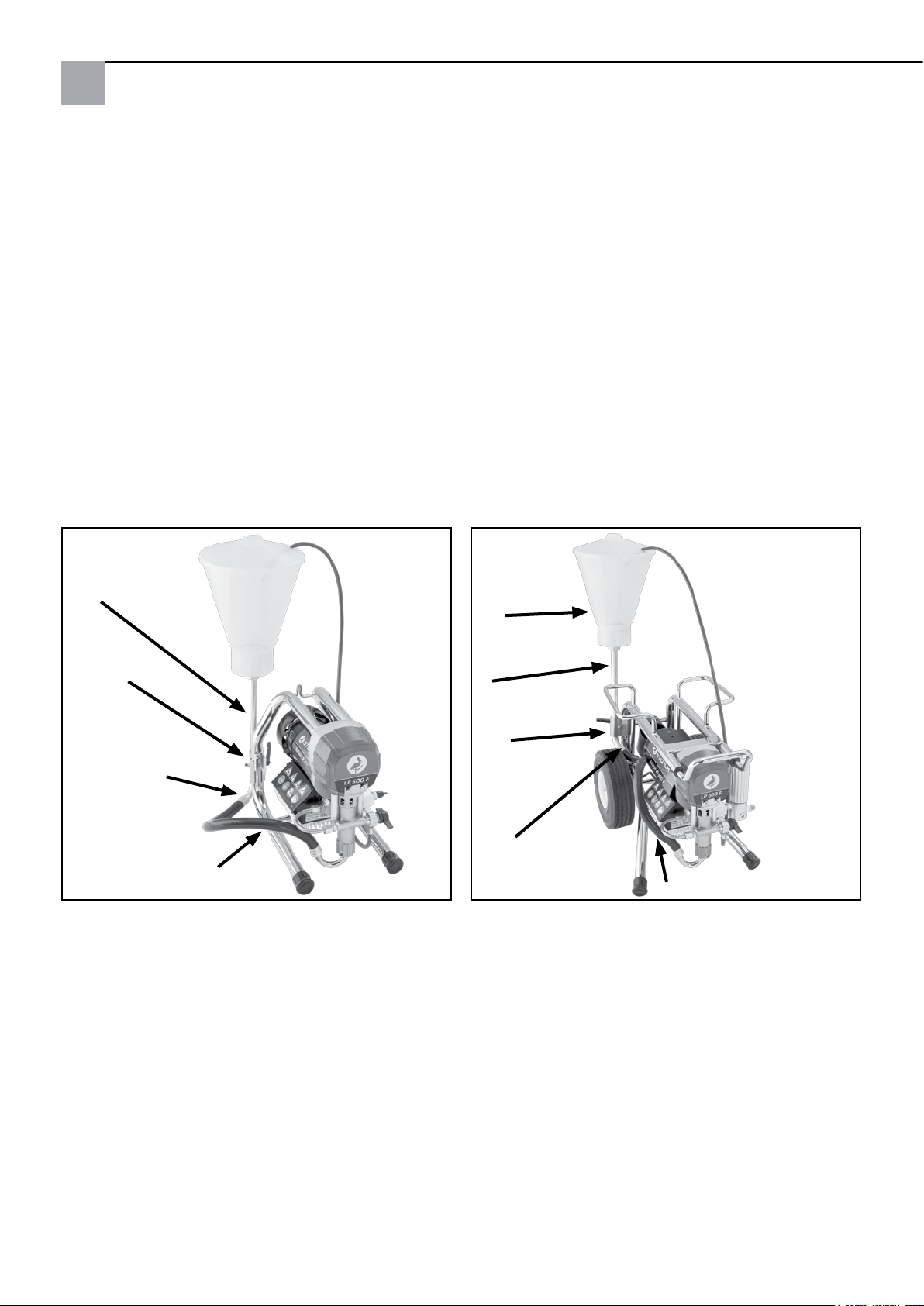
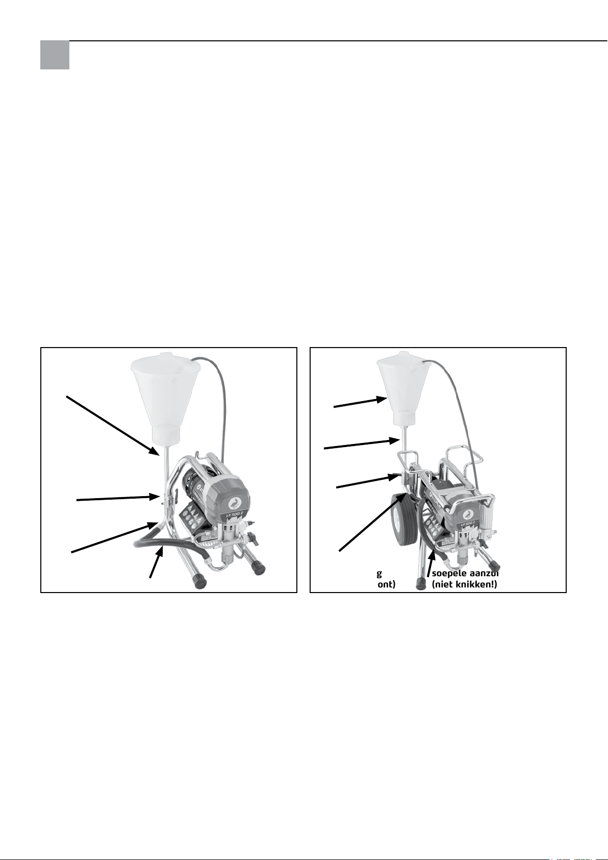
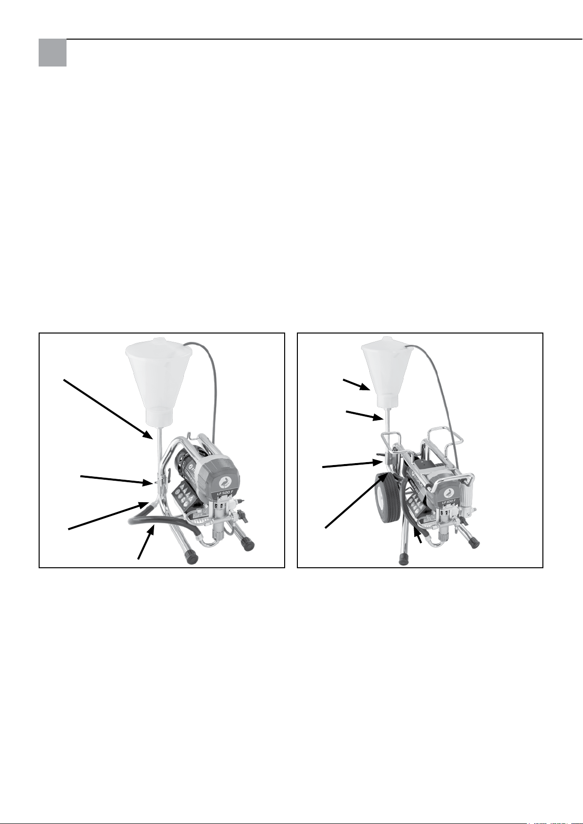
D’abord, enlevez le filtre d’aspiration du tuyau du système d’aspiration souple. Dégagez le flexible de dérivation ainsi
que la bride du flexible du tuyau d’aspiration. Placez le tuyau avec le flexible d’aspiration comme sur les photos.
Prenez soin d’éviter les courbures et les coques. (Eventuellement, vous pouvez tourner le tuyau d’aspiration dans la
compression initiale du flexible en ne faisant qu’un léger effort).
Fixez le tuyau d’aspiration A l’aide de la bride de serrage, fixez le tuyau d’aspiration sur le cadre de tuyaux.
Enveloppez le tuyau d’aspiration montant de 3 à 4 couches de ruban de teflon là où se trouve le filet et vissez-y
le réservoir supérieur.
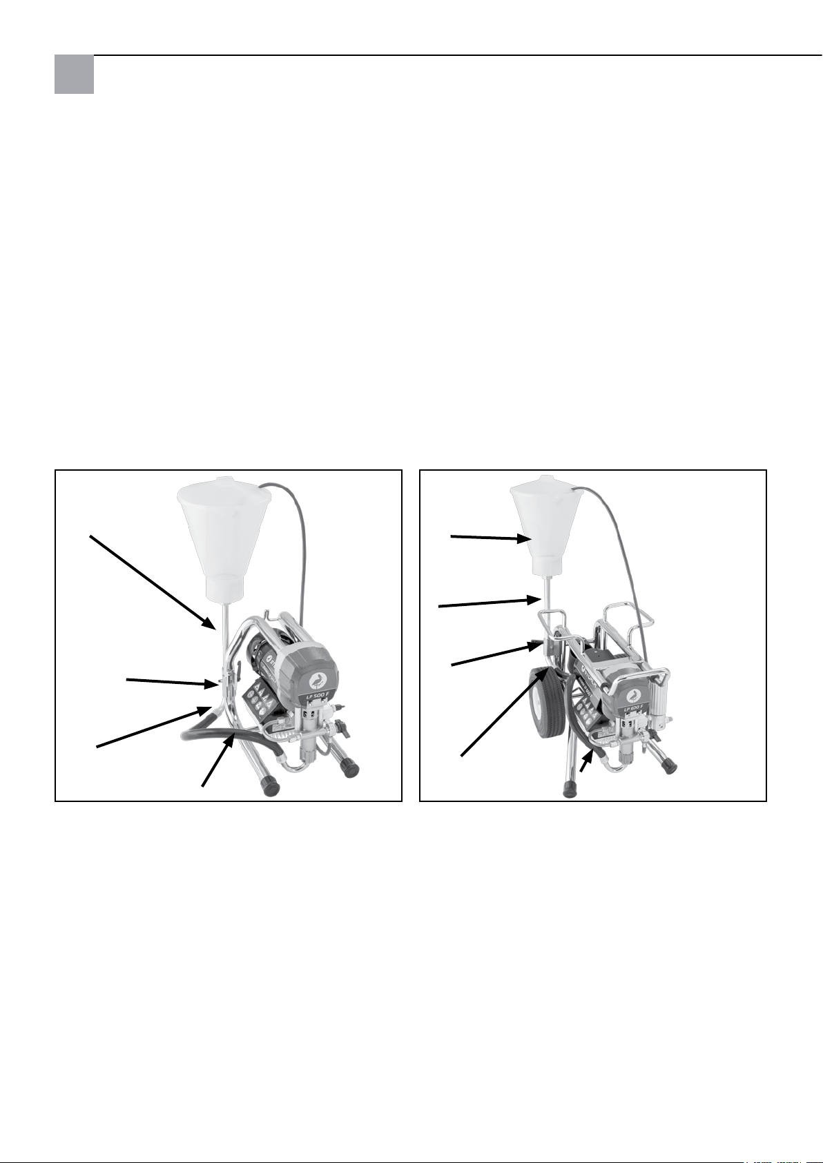
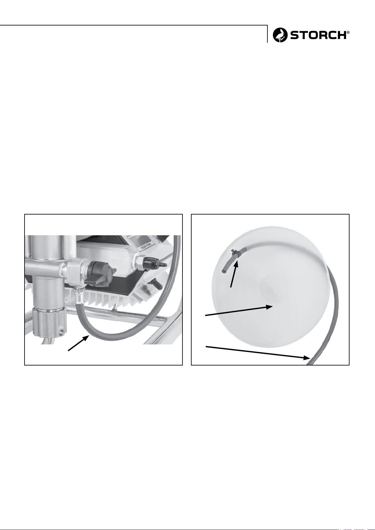
Dévissez le flexible de dérivation d‘origine, y compris adaptateur de la vanne de dérivation, et utilisez à la place le
flexible bleu fourni.
Enroulez pour cela la zone de filetage du flexible bleu avec 2 à 3 couches de la bande téflon jointe et vissez le flexible
dans le raccord de la vanne de dérivation.
Passez le bout du flexible de dérivation de l’extérieur à travers l’orifice du couvercle du réservoir (d’env. 10 cm
de large). Fixez le flexible contre tout glissement en apportant un serre-câble, comme illustré dans la photo.
Montage sur l‘appareil avec bâti porteur : Montage sur l‘appareil avec bâti roulant :

7
Mettez le tuyau sur le réservoir supérieur. L’appareil est dès maintenant prêt à l’emploi.
Vanne de dérivation
Flexible de dérivation bleu
Couvercle
Serre-câble
flexible de
dérivation
Flexible
de dérivation

8
serbatoio
tubo di
aspirazione
staffe
a morsa
(girare qui
se il tubo tubo di aspirazione flessibile
si piega) (non piegare)
tubo di
aspirazione
staffe
a morsa
(girare qui
se il tubo tubo di aspirazione flessibile
si piega) (non piegare)
IT
STORCH Reparto Assistenza
Tel.: +49 (0)2 02 . 49 20 - 112
Fax: +49 (0)2 02 . 49 20 - 244
Hotline di servizio gratuita: +49 (0) 8 00. 7 86 72 47
numero verde ordinazioni: +49 (0) 8 00. 7 86 72 44
numero verde ordinazione via fax: +49 (0) 8 00. 7 86 72 43
(solo in Germania)
Togliere anzitutto il filtro dal tubo dal sistema flessibile di aspirazione e staccare il flessibile bipasso e la molletta
reggitubo dal tubo di aspirazione. Installare indi il tubo assieme al flessibile di aspirazione nel modo raffigurato dalle
foto.
Prestare attenzione che il tubo non sia leso da piegature o da torsione. (Ripristinare, senza forzatura, sagomatura e
funzionalità del tubo ritorto).
Fissare ora al tubolare del telaio il tubo d’aspirazione servendosi del tenditore, come da fig.
Avvolgere il montante tubolare nell’ambito della sua filettatura, con 3-4 giri di nastro in teflon fornito in dotazione,
nel contempo ben rinserrando il serbatoio.
Svitare il tubo flessibile da bypass originale insieme all‘adattatore dalla valvola bypass e utilizzare il tubo flessibile blu
accluso.
Avvolgere la zona filettata del tubo flessibile blu con 2-3 strati del nastro in teflon accluso ed avvitarla nel raccordo
della valvola bypass.
Infilare indi dall’esterno l’estremità del flessibile bipasso nell’apposito foro praticato nel coperchio del serbatoio
(10 cm di largh. circa). Fissare il tubo flessibile come descritto nella foto in modo che non possa fuoriuscire.
Per eseguire ciò, utilizzare la fascetta serracavo compresa nella fornitura.
Montaggio al dispositivo con struttura portante: Montaggio al dispositivo con supporto mobile:

9
Porre il coperchio sul serbatoio. L’attrezzo è ora pronto per il suo impiego.
Valvola bypass
Tubo flessibile da bypass in colore blu
Coperchio
Fascetta
Coperchio
del serbatoio
Tubo flessibile
da bypass

10
Intake pipe
Tightening
strap
(turn here
if the hose flexible Intake hose
kinks) (do not kink!)
Upper
contai-
ner
Intake
pipe
Tightening
strap
(turn here
if the hose flexible Intake hose
kinks) (do not kink!)
GB
STORCH Service Department
Tel.: +49 (0)2 02 . 49 20 - 112
Fax: +49 (0)2 02 . 49 20 - 244
Free service hotline: 0800 786 72 47
Toll-free order hotline: +49 800 7867244
Toll-free order fax: +49 800 7867243
(only available in Germany)
Start by removing the intake filter from the hose on the flexible intake system and separate the bypass hose and the
hose chamber from the intake pipe.
Then route the pipe with the intake hose as shown in the photos. Make sure that you do not kink or twist the hose. (If
needed, you can turn the intake hose into the hose clamp by applying gentle force.)
Now use the tightening strap to fasten the intake pipe onto the frame pipe as shown.
Wrap 3 to 4 layers of the Teflon tape provided around the thread of the upward pointing intake hose and screw the
upper container onto it.
Unscrew and remove the original bypass hose incl. adapter from the bypass valve and use the enclosed blue hose
instead. To do so, warp the threaded area of the blue hose with 2 to 3 layers of the enclosed Teflon tape and screw the
trehead into the bypass valve coupling.
Feed the end of the bypass hose from the outside through the hole in the container cover (approx. 10 cm). Secure the
hose against slipping out by attaching the enclosed cable tie, as shown in the illustration.
Assembling on devices with a carrying frame: Assembling on devices with a mobile frame:

11
Place the cover on the top container. The device is now ready for use.
Bypass valve
blue bypass hose
Cover
cable tie
container
lid
bypass
hose

12
horní
nádrž
nasávací
trubka
prítlacné
desticky
(zde otocit,
pokud se pružná nasávací hadice
hadice zalomí) (nesmí se zalomit!)
nasávací
trubka
prítlacné
desticky
(zde otocit,
pokud se pružná nasávací hadice
hadice zalomí) (nesmí se zalomit!)
CZ
Servisní oddělení STORCH
Tel.: +49 (0)2 02 . 49 20 - 112
Fax: +49 (0)2 02 . 49 20 - 244
bezplatná linka Hotline-servis: 08 00. 7 86 72 47
bezplatná linka Hotline-objednávky: +49 800. 7 86 72 44
bezplatný fax-objednávky: +49 800. 7 86 72 43
(pouze v Německu)
Nejprve demontujte nasávací filtr z trubky pružného nasávacího systému a odpojte odtokovou hadici i hadicovou
svorku od nasávací trubky.
Poté trubku spojte s nasávací hadicí, jak je znázorneno na obrázcích. Dbejte na to, aby hadice nebyla zalomena
nebo prekroucena (sací trubka se prípadne dá otocit s vynaložením menší síly v míste slisování.
Nyní pomocí prítlacné desticky upevnete sací trubku k rámové trubce, viz. obrázek.
Sací trubku ukazující vzhuru omotejte v oblasti závitu 3-4 vrstvami priložené teflonové pásky a ujte zde horní nádrž.
Vyšroubujte originální obtokovou hadici vč. adaptéru z obtokového ventilu a použijte pro to přiloženou modrou hadici.
Omotejte k tomu účelu oblast závitů modré hadice 2-3 vrstvami přiložené teflonové pásky a našroubujte ji na připojení
obtokového ventilu.
Konec obtokové hadice poté zvencí protáhnete otvorem ke víku nádrže (cca. 10 cm širokým!). Hadici zajistěte proti
vyklouznutí připevněním přiloženého vazače kabelů, jak je zobrazeno na fotografii.
Montáž u zařízení s nosným stojanem: Montáž u zařízení s pojízdným stojanem:

13
Nasadte víko na horní nádrž. Nyní je prístroj pripraven k provozu.
Obtokový ventil
modrá obtoková hadice
Víko
Vazače
kabelů
víko nádrže
modrá obtoková
hadice

14

15

16
Art.-Nr. Bezeichnung
69 09 30 Oberbehälter 6 Liter
für flexible Ansaugsysteme
der LP-Serie
Art. nr. Beschrijving
69 09 30 Bovenreservoir 6 liter
voor flexibele aanzuigsystemen
van de LP-serie
Référence Désignation
69 09 30 Réservoir supérieur 6 litres
pour les systèmes d‘aspiration
flexibles de la série LP
N. art. Denominazione
69 09 30 Serbatoio di cresta 6 litri
per sistemi di aspirazione
flessibili della serie LP
Výr. č. Označení
69 09 30 Horní nádrž 6 litrů
pro flexibilní systémy sání série LP
Art. no. Description
69 09 30 Upper container 6 litres
for flexible intake systems
from the LP series
Malerwerkzeuge & Profigeräte GmbH
Platz der Republik 6 - 8
D-42107 Wuppertal
Telefon: +49 (0)2 02 . 49 20 - 0
Telefax: +49 (0)2 02 . 49 20 - 111
www.storch.de
H 002262
07-2016
Table of contents
Languages:
Other Storch Industrial Equipment manuals