Storm Shell SS-44 User manual

1
STORM SHELL
Installation Instructions for 44" Storm Shell Adapter Mounting
Plate
2
Purpose of the Adapter Mounting Plate
The 44 Storm Shell Adapter Mounting Plate is designed to be used with the 44 Storm Shell TV Hard
Cover and Wall Mount. This instruction manual is a supplement to the Assembly and Installation
Instructions for 44” Storm Shell TV Hard Cover and Wall Mount.
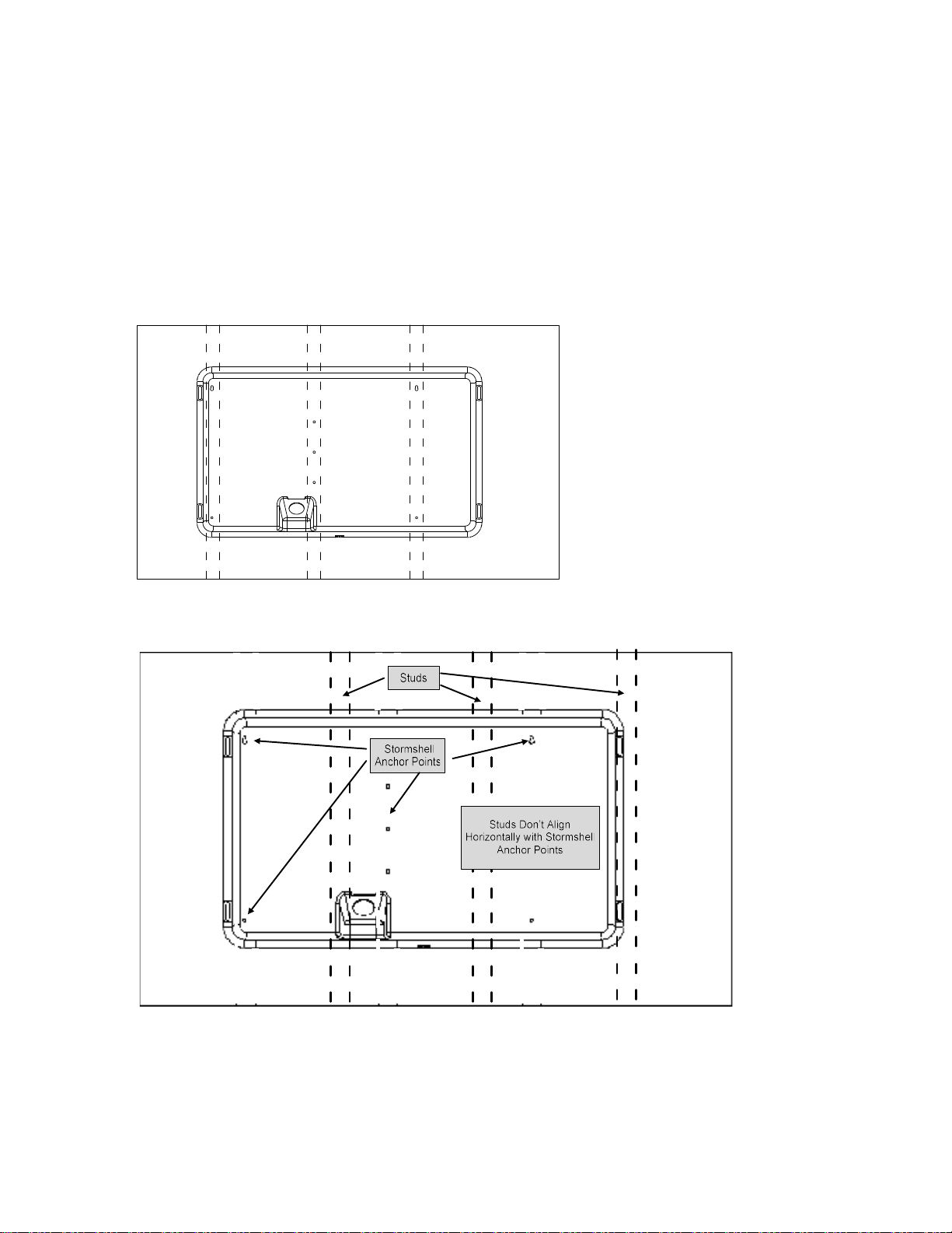
The 44” Storm Shell hard cover and TV wall mount are designed to be installed on solid concrete or
brick or on wood studs. For wood stud installation, the 44” Storm Shell is designed for installation
on three studs spaced 16” apart as shown in Figure 1. If a different horizontal placement of the 44”
Storm Shell is required to center the TV in a particular space (as in Figure 1a), or if the wall studs are
built at 20” spacing, then an Adapter Mounting Plate will be required.
Figure 1 – 44” Storm Shell is designed to mount on 3 studs spaced 16” apart
Figure 1a – Horizontal location of the 44” Storm Shell does not align between the wall studs and
the anchor points

3
Caution
Prior to installation of this product, the installation instructions should be read and
completely understood. The installation instructions must be read to prevent personal injury
and property damage. Keep these installation instructions in an easily accessible location for
future reference.
This mount and hard cover contains small parts which can act as a choking hazard if
swallowed.
CAUTION: The maximum TV load capacity is 110 lbs. (50 kg). Use with products exceeding
the maximum load capacity may cause serious injury.
The wall structure must be capable of supporting at least five times the maximum load
capacity as indicated. If not, the wall must be reinforced.
Recommended mounting surfaces: wood stud and solid-flat concrete/brick. If the mount is
to be installed on any surface other than wood studs, solid concrete or brick, use suitable
hardware (not included but commercially available).
Do not install on a structure that is prone to vibration, movement or chance of impact.
Failure to do so could result in damage to the display and/or damage to the mounting
surface.
Do not install near heater, fireplace, air conditioning or any other heat producing source.
Failure to do so may result in damage to the display and/or the hard cover and could
increase the risk of fire.
Make sure no water or natural gas lines are present where the mount is to be installed.
Cutting or drilling into water or natural gas lines could cause personal injury or property
damage.
Proper installation procedure by yourself or a qualified service technician, as outlined in the
installation instructions, must be adhered to. Failure to do so could result in serious personal
injury.
When mounting to a wall that contains wood studs, confirm the dead center of the wood
stud prior to installation, it is recommended that the wood studs be a minimum of 16" apart
(if applicable).
It is recommended that two people perform the installation. Injury and/or damage can result
from dropping or mishandling the display.
If you don't understand these installation instructions, please consult an installation
specialist.
4
Tools Required
Electronic stud finder for drywall installation
Phillips head screw driver or electric drill
Bubble Level
13 mm socket and wrench
Electric drill, 1 8
⁄" and 1 4
⁄” drill bit for wood stud installation.
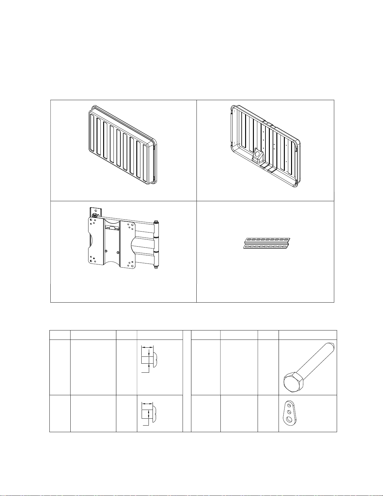
Storm Shell and TV Mounting Bracket Parts
1. Storm Shell Front 1 pc 2. Storm Shell Back 1 pc
3. TV bracket (preassembled in Storm Shell
Back ) 1 set
4. Vertical VESA Mounting Plate 2 pc
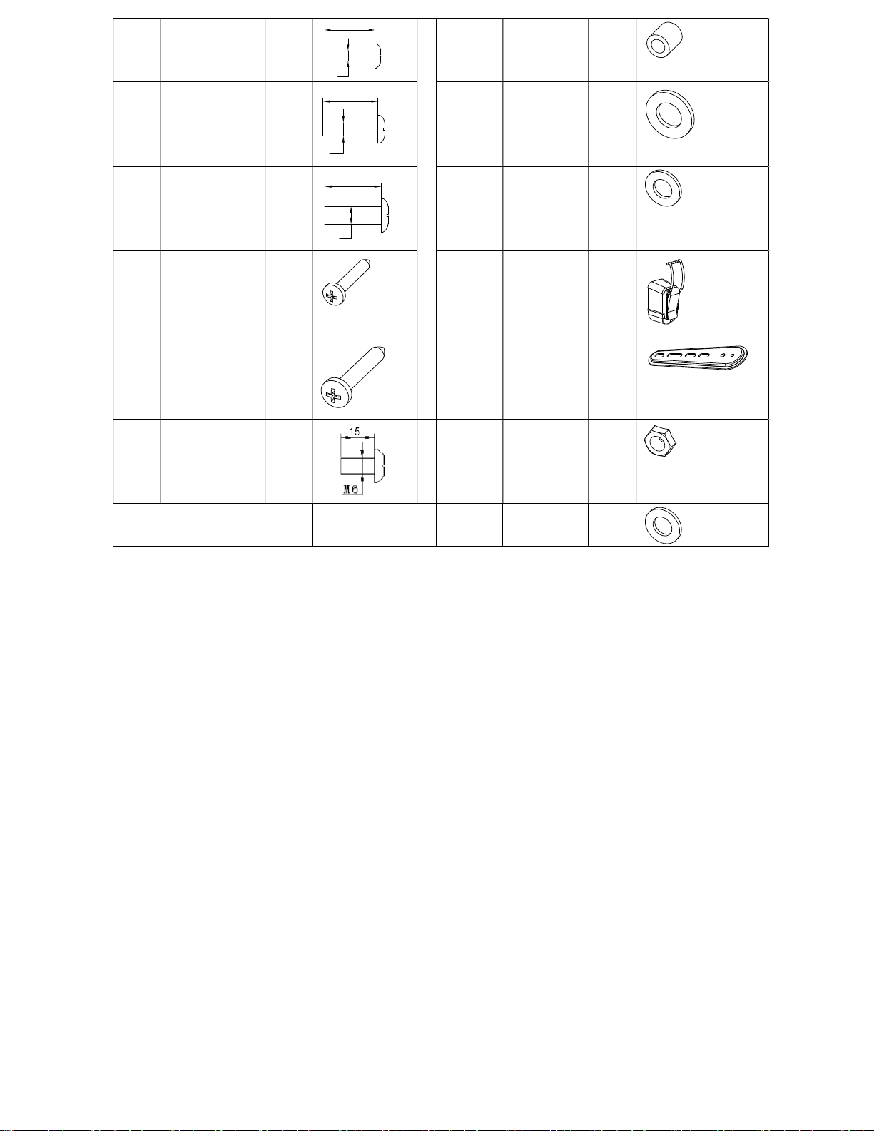
Screws :
No. Name QTY Picture No. Name QTY Picture
S1 M6X10 Screw 4
S8 ST8.0X60
Self Tapping
Screw
3
S2 M8X10 Screw 4
W1 3-hole
Washer
4
M6
10
10
M8
5
S3 M5X25 Screw 4
W2 Thick
Washer
4
S4 M6X25 Screw 4
W3 D8 Washer 3
S5 M8X25 Screw 4
W4 D6 Washer 2
S6 ST3.5X20 Self
Tapping Screw
12
B1 Buckle
Latch
4
S7 ST6X30 Self
Tapping Screw
4
B2 Extension
Bar
4
S9 M6X15 Screw 4
N1 M6 Nut 4
W5 D6 Washer 4
25
M5
M6
25
25
M8

6
44 Storm Shell Adapter Plate Parts
ITEM NAME QUANTITY PICTURE
W6 d8 washer 4
W7 d8 Spring washer 4
N2 M8 Nut 4
N3 M10 thin nut 4
S10 M8X18 screw 4
S8 ST8.0X60 self tap screw
4
adapter plate(44") 1
18
M8

7
Prepare the Storm Shell Back (same steps as in 44 Storm Shell
Instruction Manual)
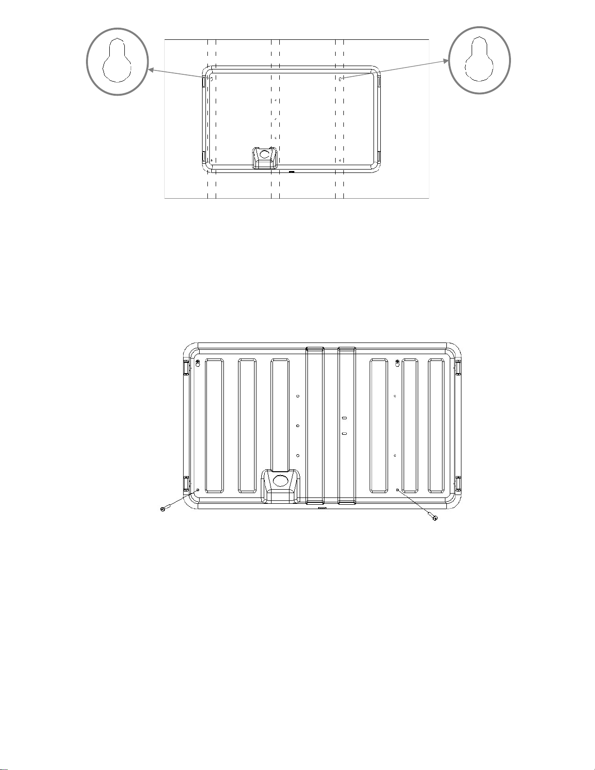
Remove the TV bracket from the Storm Shell Back by unscrewing the two shipping screws
(Figure 2).
Assemble the four buckle latches (B1) onto the Storm Shell Back using the S6 screws (Figure
3).
Figure 2
Figure 3
Install the Storm Shell Back onto the wall
Two people are needed for this installation.
A) Wood Stud Installation
1. Use a high quality electronic stud finder (commercially available) to locate dead center of three
adjacent wood studs spaced 16” apart or two wood studs spaced 20” apart. Mark the location of
each stud (Figure 4). Ensure this location mark will be visible above or below the Storm Shell Back
when it is mounted (for reference).
Figure 4
2. Determine the horizontal location for the Storm Shell Back. Next, determine the height
location for the top of the TV mounting display. Lift the Storm Shell Back into the desired location
on the wall and check the location of the Storm Shell Back in relation to the stud location (see Figure
Screws:
S6
:
ST3.5X20: 12pcs
B1: Buckle Latch
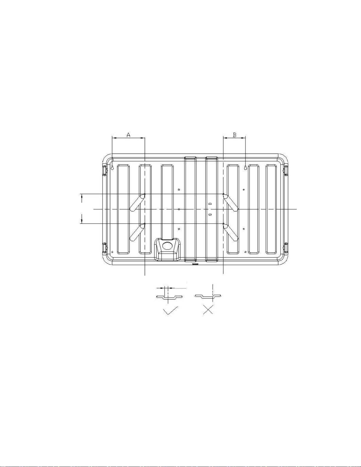
8
4a). The center of wall stud should be located on top of a ridge or in a valley of the Storm Shell Back
as shown in Figure 4a. If the center of stud is located on the edge of a ridge of the Storm Shell
Back, slide the Storm Shell Back horizontally until the center of stud is not on the ridge edge.
When the Storm Shell Back is in the correct position, make a mark through the top right key hole
(see Figure 5). Don’t worry about leveling the Storm Shell Back, just ensure that the top right
keyhole is in the correct position.
3. Remove the Storm Shell Back from the wall. Drill a hole into the wall at the top right key hole
mark using a 1 8
⁄” drill bit. Screw one of the S7 screws into this location, leaving the head about
1 8
⁄” away from the wall. Note: to more firmly secure the S7 screw into the wall, place a drywall
anchor before placing the screw. See Figure 5 below.
11 15/16"
Figure 4a
4. Lift the Storm Shell Back to the wall and position the S7 screw head (Step 3) into the top right
keyhole (Figure 5). Place a bubble level on top of the Storm Shell Back and rotate until the Storm
Shell Back is Level. Place a mark on the wall through the top left keyhole. Make sure to mark the
top left key hole at the center of the top (where the screw will rest). Remove the Storm Shell Back
from the wall. Repeat the procedure in Step 3 to drill and screw an S7 screw for the top left
keyhole. Note: to more firmly secure the S7 screw into the wall, place a drywall anchor before
placing the screw. Mount the Storm Shell Back on the wall using the mounted screws and the top
left and right keyholes. Check that the Storm Shell Back is level using the bubble level.
9
Figure 5
5. Make a mark through the bottom securing holes as shown in Figure 6. Remove the Storm
Shell Back from the wall and repeat the procedure in Step 3 to drill a hole and place a drywall anchor.
Hang the Storm Shell Back on the wall using the top key holes. Secure the S7 screws in the key
holes. Place two S7 screws with two W4 washers in the bottom securing holes and fasten so the
Storm Shell Back is tight to the wall.
Figure 6
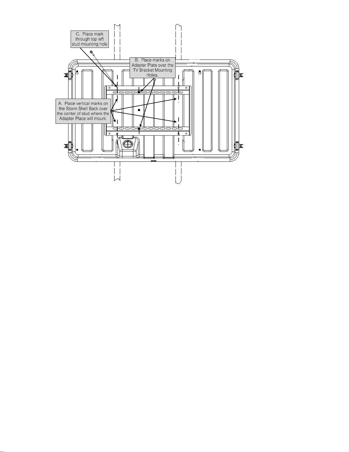
6. With the Storm Shell Back mounted on the wall, place the Adapter Plate in a position where it
spans two studs and covers the TV Bracket Mounting Holes (see Figure 7).
a. Place vertical marks on the Storm Shell Back over the center of stud where the Adapter Plate
will be mounted.
b. Hold the Adapter Plate in position and mark on the Adapter Plate where the TV Bracket
Mounting Holes are covered.
c. Hold the Adapter Plate in position and place a mark through the top left stud mounting hole
of the Adapter Plate on to the Storm Shell Back.
Top Right Keyhole
Top Left Keyhole
10
Figure 7 –
7. Remove the Adapter Plate from the wall and attach the TV Mounting Bracket to the Adapter
Plate. Place the TV Mounting Bracket on the Adapter Plate over the marks described in Step 6.b.
Place two S10 bolts through the Adapter Mounting Hole from the back of the Adapter Plate, and
place the TV Mounting Bracket over the S10 bolts. Place a W6 washer, then a W7 spring washer,
then an N2 nut over the S10 bolt. Secure the TV Mounting Bracket to the Adapter Plate using a
wrench and Philips screw driver. See Figure 8.

11
Figure 8
12
8. Drill a hole in the location described in Step 6.c. using a ¼” drill bit. Drill the Hole 3 inches
deep and ensure that the hole is into a stud. Place the Adapter Plate on the Storm Shell Back and
secure the Adapter Plate by screwing an S8 lag bolt with W3 washer through the Adapter Plate stud
mounting hole and into the drilled hole. Use a 13 mm socket wrench to secure the S8 bolt. Do
not fully tighten the S8 bolt yet. See Figure 8.
9. Use a Bubble Level to level the Adapter Plate against the Storm Shell Back. Once level, mark
the Storm Shell Back through the three remaining Adapter Plate stud mounting holes. Repeat the
procedure in Step 8 to drill and place the remaining three S8 lag bolts and W3 washers to secure the
Adapter Plate to the Storm Shell Back. Ensure that all S8 lag bolts are secured into a stud. See
Figure 8.
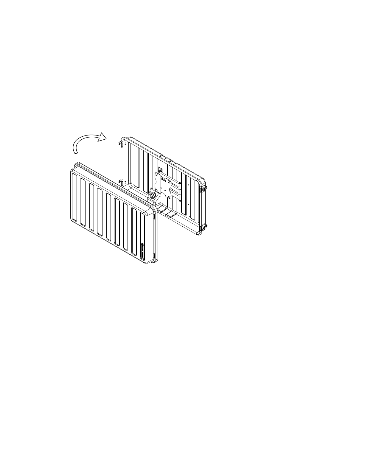
10. Install the Storm Shell Front and check that cover and latches fit correctly. Figure 9.
Figure 9
B) Concrete or Brick Installation
When installing the Storm Shell Hard Cover and TV Bracket on a concrete or brick wall, the S7 and S8
screws alone will not be sufficient. Do not attempt to use the supplied S7 and S8 screws alone on
masonry or concrete.
Several options are commercially available for concrete or brick anchors. Options include concrete
sleeve anchors or concrete screws. Consult your local hardware store or online resources to
determine the best solution for your specific wall material. Obtain proper anchors and screws to
replace the S7 and S8 screws.
The installation procedure for concrete or brick is the same as for wood stud installation with the
following exceptions:
The Adapter Plate is not required.
Locating three wood studs is not required. Determine the desired location for the Storm

13
Shell Hard Cover and proceed at Step 2 in the Assembly and Installation Instructions for 44”
Storm Shell TV Hard Cover and Wall Mount, using the selected concrete anchors.
Install the TV Display
Follow the instructions in the Assembly and Installation Instructions for 44” Storm Shell.
Table of contents


