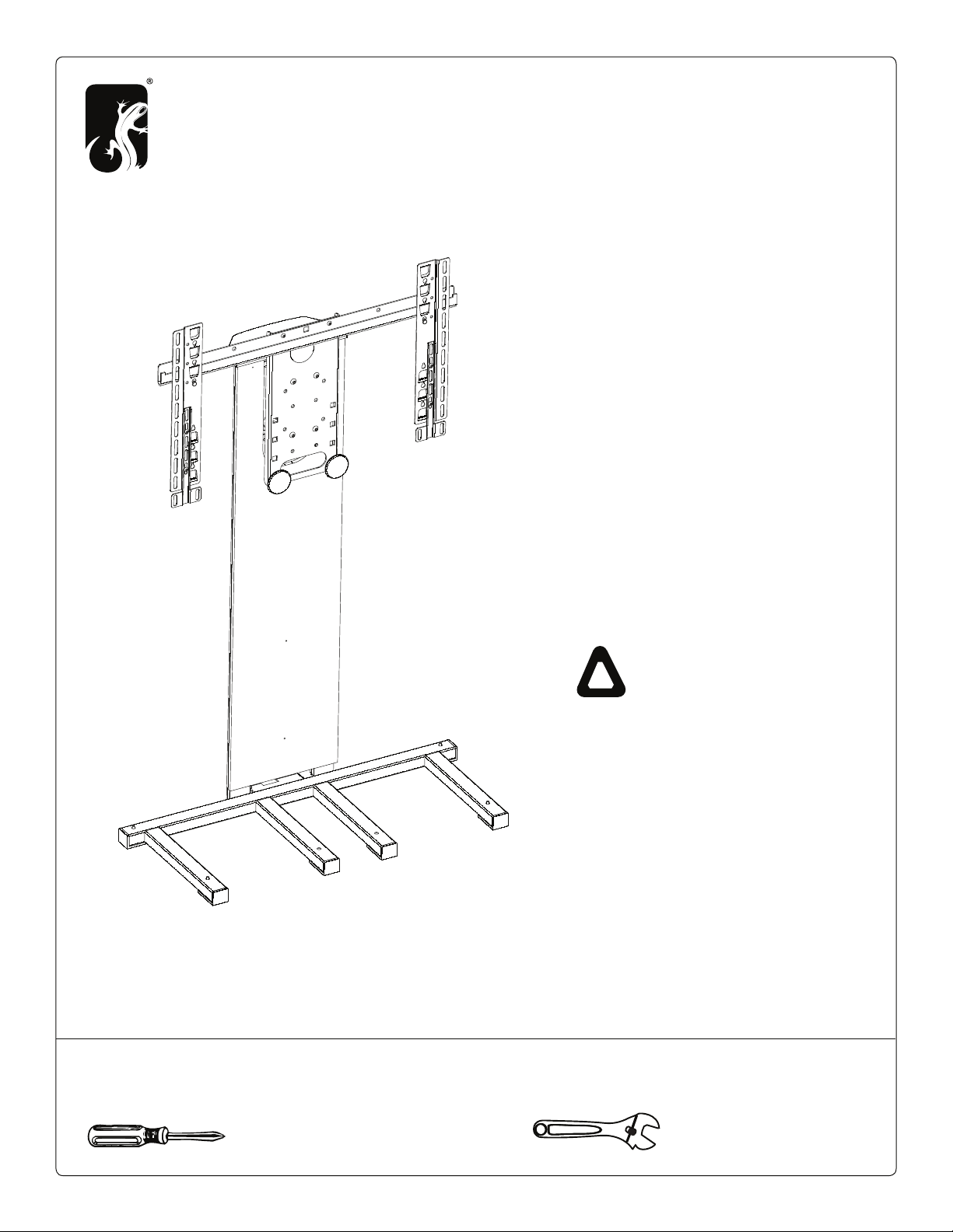
Salamander Designs Synchro FurnitureMate SYFM1 User manual

SYFM1
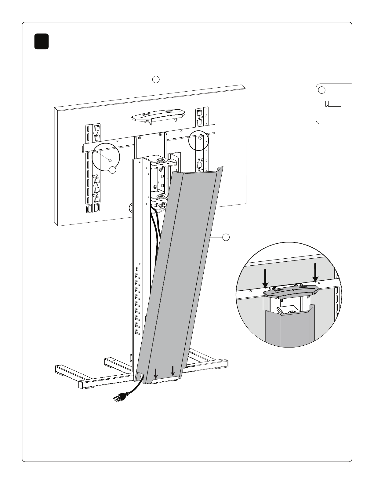
Synchro FurnitureMate Assembly Instructions
SYFM1 - 501-620 10/08 page 1 of 12
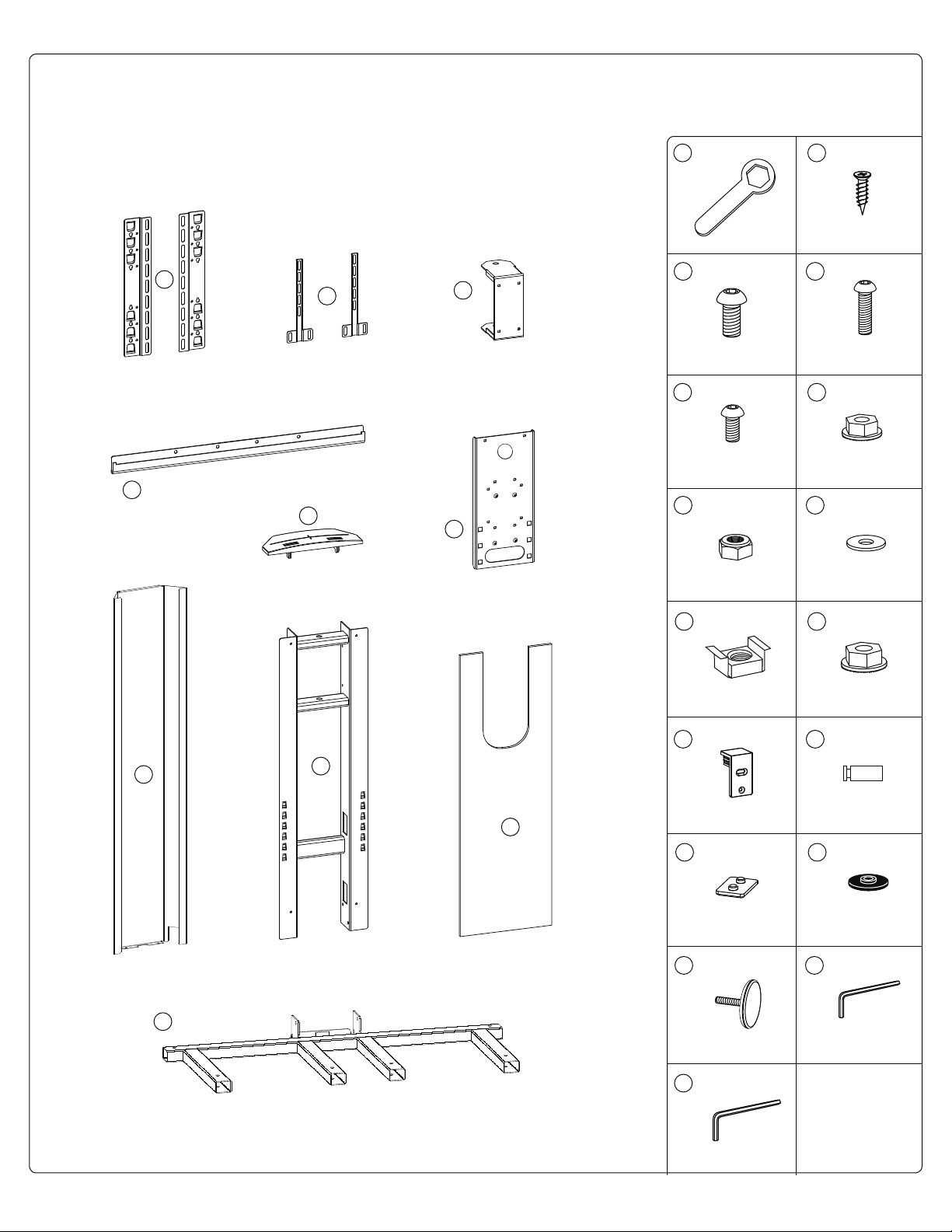
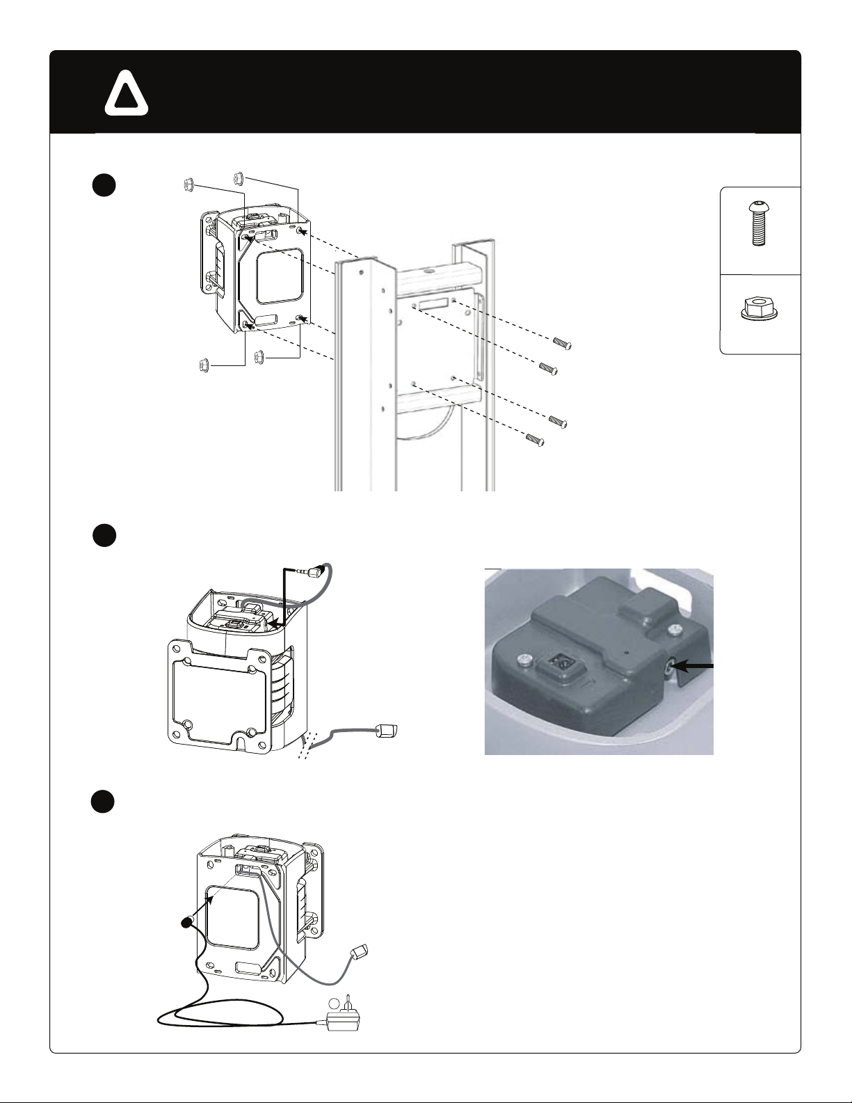
Tools Required
Phillips Screwdriver Adjustable Wrench
Thank you for purchasing the
Synchro FurnitureMate.
Unpack all content and check to ensure
that all of the parts are in proper condition.
To help protect the environment, use the
appropriate recycling and discarding
methods for the packaging items.
Read ALL assembly instructions before
assembly. If you have any questions,
please contact your installator or
Salamander Designs at 800-535-5659.
IMPORTANT
SAFETY INSTRUCTIONS
t.PVOUTNVTUCFBUUBDIFEBTTQFDJGJFEJO
BTTFNCMZJOTUSVDUJPOT*NQSPQFSJOTUBMMBUJPO
DBOSFTVMUJOTFSJPVTQFSTPOBMJOKVSZ
t5IJT57NPVOUJTJOUFOEFEGPSVTFXJUI
'MBU1BOFM57TwXJUIBNBYJNVN
XFJHIUDBQBDJUZPGMCT
t6TFPGUIJTNPVOUXJUIQSPEVDUTIFBWJFS
UIBOUIFNBYJNVNXFJHIUPSMBSHFSUIBO
UIFTJ[FJOEJDBUFENBZSFTVMUJODPMMBQTF
PGUIFNPVOUDBVTJOHQPTTJCMFJOKVSZ
t6TFUIFNPVOUJOHTDSFXTQSPWJEFEBOE
%0/0507&35*()5&/NPVOUJOHTDSFXT
t/FWFS&YDFFENBYJNVNIFJHIUPGw
DMFBSBODFGSPNCPUUPNPG57
!

SYFM1 - 501-620 10/08 page 2 of 12
Parts
27
25 26
2x M6 Allen 4 1x
9
10 7
6
8
5
3
2
4
1
2423
2x 4x
21 22
6x 2x
2019
2x
17 18
1615
13 14
1211
1x M4x10 6x
M8x16 10x M6x25 4x
M6x12 4x M6 4x
M8 Nut 10x
M6 2x M10 Washer 2x
M8 Allen 5 1x

2Attach Back Panel
1Assemble Frame
SYFM1 - 501-620 10/08 page 3 of 12
Reversible Back Panel Note
4X
13
6X
21
12
6X
1
3
2
3
23
2X
23
13
21
4X
20
20
27
1X
12

3Assemble Rotary Mechanism - Manual Option Only
For Motorized Assembly, See Step 4
SYFM1 - 501-620 10/08 page 4 of 12
A
4X
24
2X
18
2X
17
711
1X
18
24
24
17
B
C

4X
4X
4Assemble Rotary Mechanism - Motorized Option Only
SYFM1 - 501-620 10/08 page 5 of 12
A
B
ARemove Plastic Caps from the top and bottom

SYFM1 - 501-620 10/08 page 6 of 12
A
C
D
E
Connect IR Cable
Connect Power Cable
4X
4X
8
DANGER: ELECTRIC SHOCK HAZARD!
Do not provide power to mount when front covers are removed.
Always use caution when working in or around mount when front covers are removed.
!

5Install TV Mount
SYFM1 - 501-620 10/08 page 7 of 12
13
6X
19
20
25
2X
6X
2X
6
8
Optional XL Bracket
13
20
20
13
25
19
27
1X
Align rotary mechanism holes to preferred
adjustable hole pattern on mounting plate.
A
B
With height adjustable
mounting hole patterns.
TV Leveling Supports
Adjust after installing TV

SYFM1 - 501-620 10/08 page 8 of 12
6Attaching TV Bracket
Height
Mounting Hole Width: Mounting Hole Width:
Width
3
6
9
2
5
8
Screw 4x16mm 6x
1
4
7
Screw 5x12mm 6x Screw 5x30mm 6x
Screw 6x12mm 6x Screw 8x40mm 6x Screw 8x16mm 6x
Screw 6x30mm 6x Spacer 8mm 6x
Washer 6mm 6x
Washer 5 mm 6x
Washer 4mm 6x
Washer 8mm 6x
10 11 12
9
9
24.5” - 32.4” (62 cm - 82 cm) 7.9” - 24.5” (20 cm - 62 cm)
Screen Fixing Fasteners
Allen 3 1x Allen 4 1x Allen 5 1x

7Set TV On Stand
SYFM1 - 501-620 10/08 page 9 of 12
3 If Mounting Hole Height Exceeds : 15.75” (40 cm) Use Extensions
15 16
9
10
4X 4X

8Safety Fasteners, Cable Management & Cap Installation
SYFM1 - 501-620 10/08 page 10 of 12
D
22
2X
4
5
22

Left / Right and Favorite Position Operation Notes:
The factory settings are made for the maximum left and right stop positions (+/- 30 °) and the
favorite position is preset to the center. You may adjust other stop (left, right) positions and another
favorite position to restrict the movement of the screen during rotation, to prevent collision with objects around it
and to provide for optimum visual comfort. The screen rotation movements occurs only as the left or right
arrow is held down. The movement stops when the key (left or right) is released. Pressing the Up arrow brings
the PILOTMOTION back into its preference position, center. Pressing one of the left or right arrows interrupts the
cycle via which the PILOTMOTION moves back into its preference position.
SYFM1 - 501-620 10/08 page 11 of 12
A
9Attach IR Sensor - Motorized Option Only
A. Pull the tab at the bottom of the remote control to enable the battery.
B. Plug in the PILOTMOTION power supply cable.
C. Adjusting the Stops and Preference Position.
To access the program mode press the following sequence:
Left arrow, Up arrow, right arrow, left arrow, Up arrow, right arrow ( , , , , , ).
The PILOTMOTION will make a long beeping sound.
Adjusting the favorite position: Put the PILOTMOTION into the desired position using the left
and/ or right arrows. Once the desired position has been reached, validate by pressing the Up
arrow ( ). ( 2 short beeping sounds: “beep” “beep”).
Adjusting the left stop: Press the left and right arrows ( , ) until the desired position has been
reached. Validate by pressing the Down arrow ( 2 short beeping sounds: “beep” “beep”).
Adjusting the right stop: Press the left and right arrows ( , ) until the desired position has been
reached. Validate by pressing the Down arrow ( 2 long beeping sounds: “beeeep” “beeeep”).
The PILOTMOTION is then set. In the event of a power cut, the settings will be saved. They may be
modified using the same procedure.
,
Note: IR Sensor must be
placed where signal can
be reached at all angles.
10 Programming Remote

SYFM1 - 501-620 10/08 page 12 of 12
SALAMANDER DESIGNS LIMITED WARRANTY
Salamander Designs Ltd. (Salamander) provides the following Limited Warranty. The Limited Warranties herein described
for the specific products listed below shall be in lieu of any other warranty, expressed or implied, including but not
limited to any implied warranty of merchantability or fitness for a particular use. These Limited Warranties do not cover
damages incurred in shipment, failures caused by other products not supplied by Salamander, or failures due to accident,
misuse, abuse or alteration of the product. Salamander’s sole liability and the purchaser’s exclusive remedy shall be for
the repair, or at Salamander’s option, for the replacement of the defective part as provided herein. Notwithstanding the
above, if replacement parts for defective materials are not available, Salamander reserves the right to make reasonable
compensation in lieu of repair or replacement. Liability for incidental or consequential damages under the warranty is
excluded. Some states do not allow limitation of incidental or consequential damages. Therefore, the above limitation
may not apply in certain instances. Defective product must be given Return Authorization by Salamander and is to be
returned to the factory prepaid, in the original carton and packing materials. Any damage incurred in a shipment not in
original packing shall be the responsibility of the owner. Warranty repairs will be returned to the owner prepaid, within
the continental U.S.A. only. This warranty gives you specific legal rights and you may also have other rights which vary
from state to state.
Salamander Audio/Video Mount Warranty Limitations
MANUAL MOUNTS
Salamander provides a five (5) year Limited Warranty from the date of the purchase, on material damage and/or
manufacturing defects. Salamander guarantees that if, during the warranty period, any defects should occur in the
product resulting from faulty material and/or assembly, as assessed by Salamander, the product will be repaired or, if
necessary, replaced free of charge. The warranty expressly does not apply to normal wear and tear that becomes
apparent after normal use.
MOTORIZED MOUNTS
Salamander provides a two (2) year Limited Warranty on motorized mounts. This warranty covers the repair or
replacement, at Salamander’s option, of any product defective in materials or craftsmanship. Batteries are not covered
by the warranty. Other limitation apply (See entire Mounts Warranty)
WARRANTY PROCEDURE
Claims should be made through the dealer from which the product was purchased. The dealer will contact Salamander
Designs Ltd. (Salamander) for warranty service. An original sales order number/purchase order number will be required for
warranty protection. Salamander’s liability under this warranty is limited to repairing or replacing at Salamander’s option
any part or parts of the product found to be defective in material or workmanship within the applicable warranty period.
Salamander in its sole discretion will determine the cause and nature of any defect, the necessity and manner of repair or
replacement, and all other matters pertaining to the condition of the product.
LABOR AND SHIPPING CHARGES
Should you be entitled to receive a repair or replacement under this warranty, Salamander will pay the cost of labor,
handling and shipping to the consumer for two (2) years from the date of purchase by the original consumer. After that
date, the purchaser will be responsible for these costs.
phone: 800-535-5659
web: SalamanderDesigns.com
CAUTION: CONTACT BETWEEN TV AND WALL CAN CAUSE DAMAGE TO EQUIPMENT.
Allow some clearance between TV and wall when setting TV travel limit.
WARNING: PINCH HAZARD! FINGERS OR HANDS BETWEEN MOVING PARTS CAN
LEAD TO SEVERE PERSONAL INJURY! Keep hands away from mount when operating.
WARNING TIP HAZARD: Always remove TV from mount before moving stand.
!
Table of contents
Other Salamander Designs TV Mount manuals