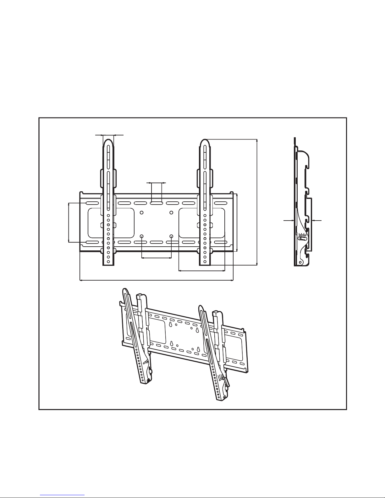
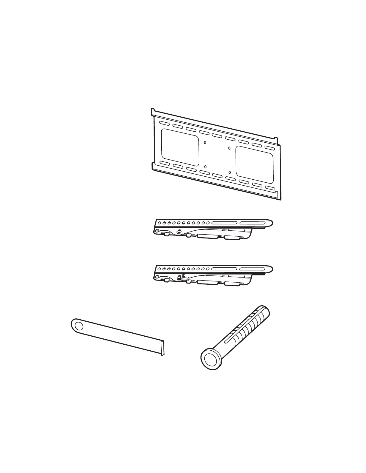
Monster FlatScreen Mount SmartViewTM 300M User manual

SmartView
™
300M
FlatScreen Mount
Support d’écran plat
SmartView
™
300M
Base
SmartView
™
300M
FlatScreen para
televisores planos
USER GUIDE & WARRANTY
GUIDE ET GARANTIE D’UTILISATEUR
GUÍA DEL USUARIO Y GARANTÍA


A NOTE FROM THE HEAD MONSTER
Dear Enthusiast,
THANK YOU
for purchasing the Monster
®
SmartView
™
300M FlatScreen Mount. The
SmartView 300M refl ects our passion for creating
the industry’s most innovative and practical AV
solutions, so enthusiasts like yourself always
experience the absolute best from their high
performance AV components. The SmartView
300M is the only fl at-wall mount on the market that
allows instant height and tilt adjustments without
tools or disassembly, so it’s always easy to get the best view.
Noel Lee,
The Head Monster

More Great Products
from Monster FlatScreen
™
The Look You Want. The Performance You Need.
Monster FlatScreen Cables
™
Ultra slim and fl exible, Monster FlatScreen
Cables ensure a clean, no-clutter hookup
to your thin display. Plus, they feature advanced
Monster Cable technologies, so you always get
the best possible picture and sound.
Monster FlatScreen PowerProtect
™
and PowerCenters
™
Safeguard your fl atscreen investment
from harmful electrical surges and “dirty”
AC power with exclusive Monster Power
®
technologies, including Monster
SurgeGuard
™
and Monster
Clean Power
.
™
Monster FlatScreen Clean
™
Our safe LCD and plasma cleaning
solution instantly removes dust,
dirt and fi ngerprints from your fl atscreen
without drips, stains or scratches.
For more details on all our Monster FlatScreen products,
visit us at
MonsterCable.com/FlatScreen

1
SmartView
TM
300M FlatScreen Mount
SmartView 300M is designed to mount
24"
-to-
37"
LCD and plasma televisions
to vertical walls. Maximum weight capacity is
100 lbs.
SAFETY WARNING:
If you don’t understand these directions, or have doubts
about this product’s installation, please call a qualifi ed contractor or contact
Monster Cable Products, Inc. at
1-877-800-8989.
Before installing, carefully review the instructions to ensure that no parts are
missing or defective. Improper installation can cause damage or serious injury.
Do not use this product for any purpose not explicitly specifi ed by Monster.
Monster is not liable for damage or injury caused by incorrect assembly,
incorrect mounting or incorrect use.
All hardware is supplied for the following wall conditions: Wood stud, brick,
solid concrete, and concrete block.
Note:
The supplied hardware
is not for walls with steel studs.
If you
are uncertain about the nature of your wall construction, consult
an installation contractor.

Specifi cations and Notes:
Monster is constantly striving to improve its products.
Specifi cations are subject to change without notice.
2

Required Tools
Wall Stud Mounting:
Electronic stud sensor
Level
Electric hand drill
3/16" drill bit
Phillips screwdriver
Combination wrenches or socket set
Masonry Mounting
(brick, concrete, concrete blocks):
Above tools
Replace 3/16" drill bit with 1/2" masonry drill bit
•
•
•
•
•
•
•
•
3

Package Contents
If any parts are missing, please call 800-877-8989.
1 Wall Plate
2 Tilting Vertical
Adjustment Bars
4 Concrete Anchors
1 L-Shaped Locking Bar
4

4 Square Washers
4 Round Washers
4 Spacer #1
4 Spacer #2
Screws
4 ea. M4x15/M4x35/M4x45
4 ea. M5x15/M5x35/M5x45
4 ea. M6x15/M6x35/M6x45
4 ea. M8x15/M8x35/M8x45
4 Lag Bolts
1 Bubble Level
5

Cautions and Warnings
Forbidden Actions:
Do not install on a sloping surface. Install exclusively
on a vertical surface.
Do not install in a room with excessively high temperatures
or high humidity.
Do not install near an air conditioner.
Do not install in a location with excessive dust, smoke or moisture.
These sources can create a fi re.
Do not apply unnecessary stress or load on the installed unit.
Do not install unit alone. Safe installation requires at least
two people.
Do not route your fl atscreen TV’s power cord in wall. Check local
building/electrical codes for more information.
Cautions:
To prevent eye fatigue, do not install where there is direct sunlight
or excessive light.
When carrying out maintenance, disconnect the TV’s power supply
to avoid electrical shock.
If planning to route AV cable in wall, only use cable UL-certifi ed
for this use.
6

Pre-Installation Checklist
Is the view of your mounting location free of glare
and other obstructions?
If mounting to two wall studs, is your mounting location’s
stud separation less than 19"?
Is there an AC power outlet within range of your mounting location,
preferably behind the placement of your display?
Is your mounting location at least 3 ft. from any source of heat or water?
To hide your TV’s power cord, install a Monster
®
In-Wall PowerCenter
® In-Wall PowerCenter
®
™
behind the placement of your display.
®
®
®
®
7

Installing the Wall Plate
Remove all pieces of the wall mounting system to ensure you have all
the necessary parts.
Be sure to choose a mounting location with easy access
to an AC power outlet.
Wood Stud Mounting:
Using an electronic stud sensor, locate two adjacent wall studs
at least 12" apart.
With the help of a friend, align the wall plate’s top and bottom
horizontal mounting slots over the center of each wall stud.
Level the wall plate with the bubble level.
Hold the plate fi rmly in place.
Mark the stud center in each of the four slots (bottom left,
top left, bottom right, top right).
With your electrical drill and 3/16" bit, pre-drill a 3" deep
hole at each mark.
Attach the wall plate to the wall using the lag bolts and round washers
as shown to the right. Tighten each bolt with your electric drill or socket
wrench. Turn clockwise until secure.
DO NOT over tighten bolts. This can damage the wall plate
or the surface of your wall.
DO NOT release the wall plate until you are absolutely certain
it is secured to the wall.
1)
2)
3)
4)
5)
6)
8

9

Installing the Wall Plate
continued
Masonry Mounting
While masonry materials (bolts and concrete anchors) are included, masonry
mounting requires specialized knowledge, skills and tools. Monster highly
recommends you seek the assistance of a professional installer when
mounting to masonry.
DO NOT drill holes in masonry mortar joints.
With the help of a friend, position the wall plate in your desired
mounting location. Level the wall plate with the provided bubble level.
Mark the centers of four bolt slots as shown to the right. Be careful not
to mark a mortar joint.
With your electrical drill and 1/2" masonry bit, pre-drill a 3" deep hole
at each mark.
Install the supplied plastic concrete anchors in each hole. Tap into hole
until fully seated.
Attach the wall plate to the wall using the lag bolts and round washers
as shown to the right. Make sure fl at center of the plate is facing the wall.
DO NOT over tighten bolts. This can damage the wall plate
or your wall surface.
DO NOT release the wall plate until you are absolutely certain
it is secured to the wall.
1)
2)
3)
4)
10

11

Attaching the Tilting Vertical Adjustment Bars to the TV
DO NOT lay your TV face down when attaching the Tilting Vertical
Adjustment Bars. This can cause permanent damage to your
screen. Lean it against a wall or other solid surface so it remains
vertically upright.
Your TV should be unplugged before threading any bolt or screw
into the back panel.
Your mounting system features 12 sets of screws of varying diameter and
length. Before attaching the adjustment bars to your display, determine which
screw set is correct for your display.
TVs with fl at backs use a shorter screw without a spacer. TVs with curved backs
or recessed inserts may require a longer screw with a spacer between the TV
and adjustment bars. Smaller M4, M5 or M6 screws require a square washer
(supplied) between the adjustment bar and each screw.
Locate the threaded inserts on your TV’s back panel. Thread a screw
from the set into one of the inserts to ensure it is the correct choice.
Thread screws through the adjustment bars into the TV inserts with the
appropriate spacer and washer set, if needed. Make sure to install each
adjustment bar so its
Pull ‘n’ Twist
™
Pull ‘n’ Twist™
Pull ‘n’ Twist
handle faces the outer edge of the TV.
With a Phillips screwdriver, tighten the screws so the adjustment bars
are fi rmly attached to the TV.
DO NOT over tighten screws. Thread screws carefully by hand before
tightening. If you feel any resistance, remove the screw immediately.
1)
2)
3)
12

WARNING
DO NOT OVER TIGHTEN SCREWS.
13

Hanging the TV and Tilting Vertical Adjustment Bars
on the Wall Plate
Make sure the tilt mechanisms are locked before you mount the TV.
For full instructions, refer to page 16.
Monster strongly recommends that a minimum of two people
perform the following steps.
DO NOT release the TV until you are certain it is properly mounted
and secured to the wall plate.
Connect the TV’s power cord and any AV cable to the TV before hanging
it. With the help of a friend, lift the TV and plug its power cord into a
nearby AC outlet. If routing AV cable in wall, route the cable through the
wall plate’s Pass-Thru slots into the prepared opening in your wall.
Locate the two sets of
QuickLift
™
QuickLift™
QuickLift
hooks on the back of the Tilting Vertical
Adjustment Bars, now attached to your TV.
Hang either the upper or lower pair of
QuickLift
hooks on the wall plate’s
QuickLift hooks on the wall plate’sQuickLift
top and bottom horizontal channels. (See diagram on opposite page.)
The higher display position requires an additional 3" of audio/video cable
and power cord length.
Secure the display with the L-Shaped Locking Bar. Slide it horizontally
through the slot below either bottom hook.
The locking bars should always be used to reduce the risk of seismic
damage. A padlock can be added for additional theft deterrence.
1)
2)
3)
4)
5)
6)
14

15

Adjusting Your TV’s Tilt and Height
Tilting Your TV:
With a person on each side of the TV, turn the
Pull ‘n’ Twist
™
Pull ‘n’ Twist™
Pull ‘n’ Twist
handles
downward as far as you can. This loosens the tilting adjustment bars
and initiates tilt.
To further loosen the adjustment
bars and increase ease of tilt, pull
outward on the round portion
of the handle. This initiates its
ratchet mechanism.
In ratchet mode, turn the handle
upward to its highest point.
Release the handle to disengage
ratchet mode. When handle clicks
into place, it’s ready to be turned
downward again. Repeat Step 1.
To prevent stress on TV, ensure both
bars are tilted at the same angle.
To lock the bars into place
at the desired angle, do the reverse
of the steps above. Turn
the handles upward and ratchet
as needed until the bars are secure.
1)
2)
3)
4)
5)
6)
16
This manual suits for next models
1
Table of contents
Languages:
Other Monster TV Mount manuals

Monster
Monster MTTVMT26-65 User manual

Monster
Monster PERFECTVIEW 450L User manual

Monster
Monster PERFECTVIEW 450M User manual

Monster
Monster MTTVMT47-100 User manual

Monster
Monster SmartView 200M User manual

Monster
Monster SMARTVIEW 300L User manual

Monster
Monster MTTVMT14-55 User manual

Monster
Monster MTTVMT26-60 User manual

Monster
Monster FlatScreen Mount SmartViewTM 200L User manual

Monster
Monster PERFECTVIEW 400S User manual